

SportsArt Fitness 6100, 6100E, 6150, 6150E Repair Manual
6100/E/6150/E Treadmill Repair Guide
SPORTS ART INDUSTRIAL CO., LTD.

SPORTS ART INDUSTRIAL CO., LTD.
6100/E/6150/E Series Treadmill Repair Guide
Chapter 1. Treadmill Configuration and Wiring Diagrams
Chapter 2. Operation
Chapter 3. Error Message Definitions
Chapter 4. Measuring and Testing
0-0-1

6100/E/6150/E
1. Treadmill Configuration and Wiring Diagram
SPOR TS AR T INDUSTRIAL CO., L TD.
SPORTS ART INDUSTRIAL CO., LTD.
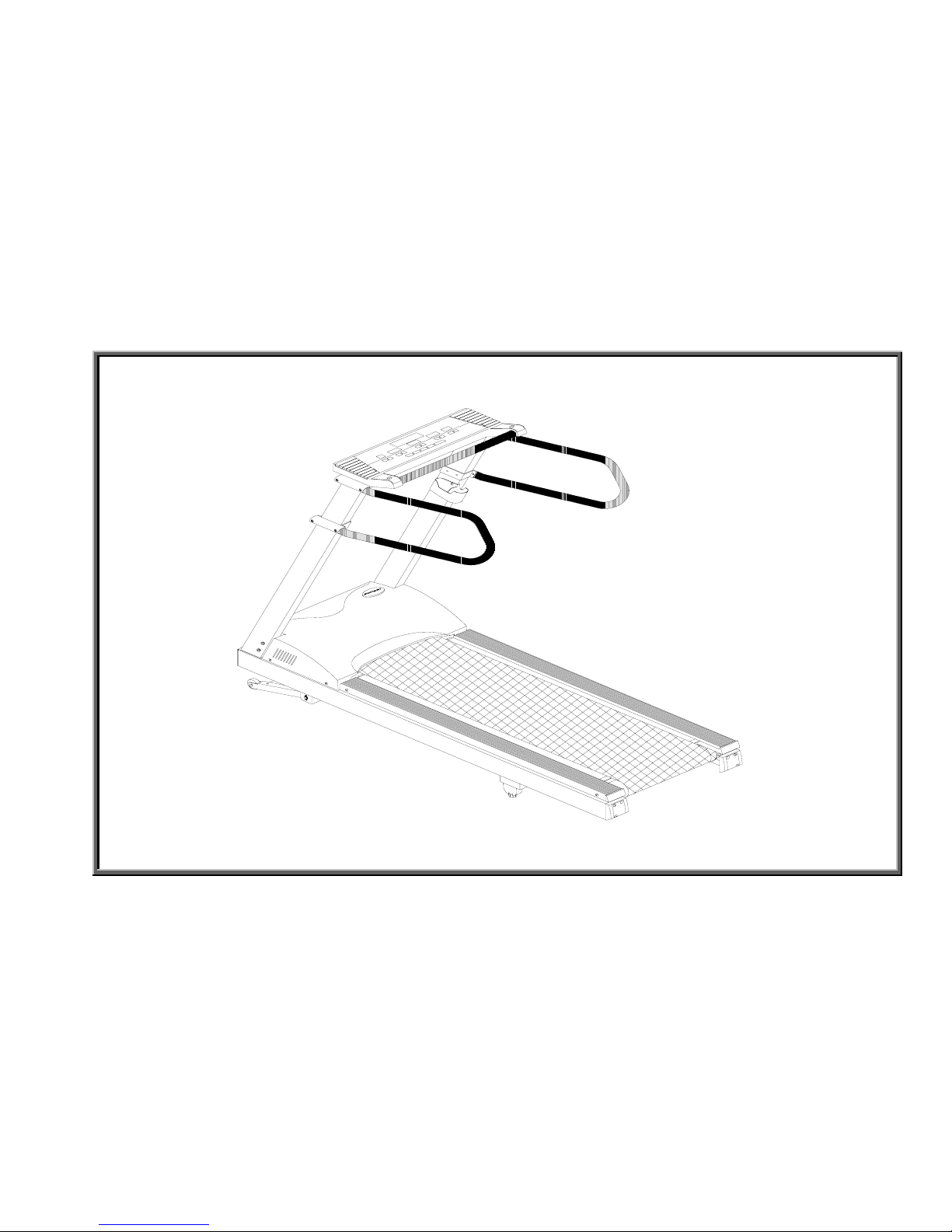
6150E/6100E Treadmill
1-1-1
SPORTS ART INDUSTRIAL CO., LTD.
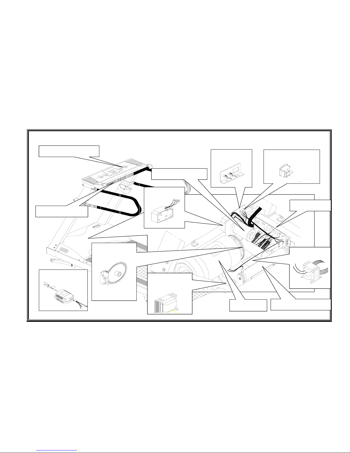
6150E/6100E Treadmill Electronic Component Placement Diagram
1-2-1
Display Window
HTR Handlebar
Motor
Optic Sensor
+Tachometer
Incline VR
Fuse Socket
On/off Switch
Inductor
(220V)
Resistance Resistor
Transformer
Drive Board
Incline Motor Set
Power Filter
SPORTS ART INDUSTRIAL CO., LTD.
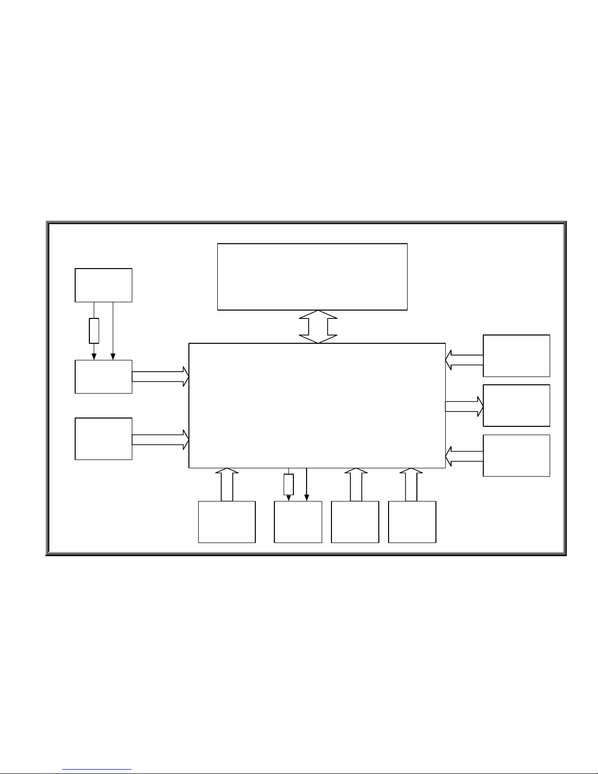
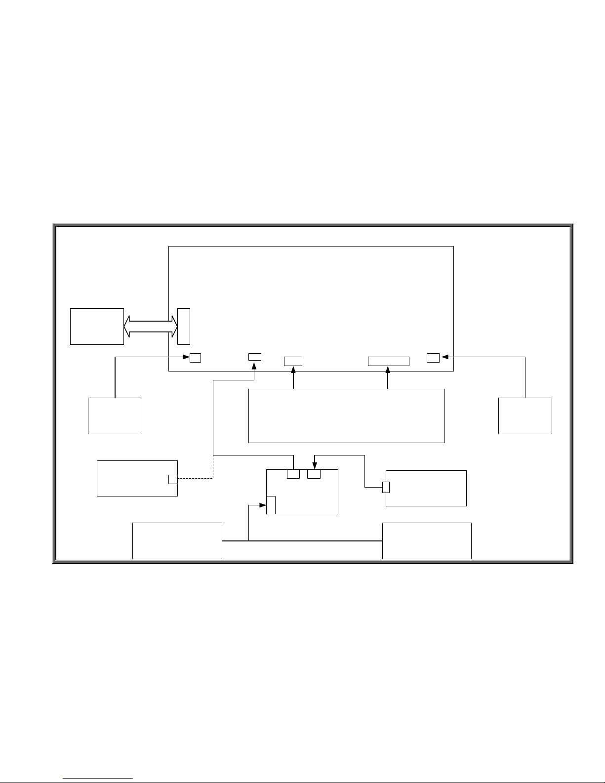
6150/E/6100/E Treadmill Configuration
Display
Drive Board
Motor
Optic Sensor
Large
Resistor
(FUSE)
Transformer
Incline
Motor
Incline
VR Set
Inductor
(220V)
Incline
LIMIT
Switch
Power Cord
(Filter)
On/Off
Switch
2-PIN
3-PIN
2-PIN
16- PIN
Cable
2-PIN
2-PIN
3-PIN
FUSE
2-PIN
10-PIN
FUSE
1-3-1
SPORTS ART INDUSTRIAL CO., LTD.
6150/E/6100/E Display Board Wiring Connection Diagram
6150 Soft Keys
HTR BOARD
HTR HANDLEBAR HTR HANDLEBAR
STOP
Board
STOP
Board
POLAR Receiver
K1K2
STOP
1
STOP2
CNT3
CNT1
CN1
CN2
CN3
6150 Display Board Backside
POLAR RECEIVER
TO Drive
Board
16-PIN
1-4-1

SPORTS ART INDUSTRIAL CO., LTD.
6150/E/6100/E Drive Board Wiring Connection Diagram
Large
Capacitor
Power
Switch
Inductor
(
220V)
Incline Set
(Motor
,VR,
LIMIT Switch)
Transformer
Display
Board
Motor
Optic
Sensor
1
6
P
I
N
7 pin
7 pin
Power Cor
d
and Filter
FUSE
4
p
i
n
1-5-1
SPORTS ART INDUSTRIAL CO., LTD.
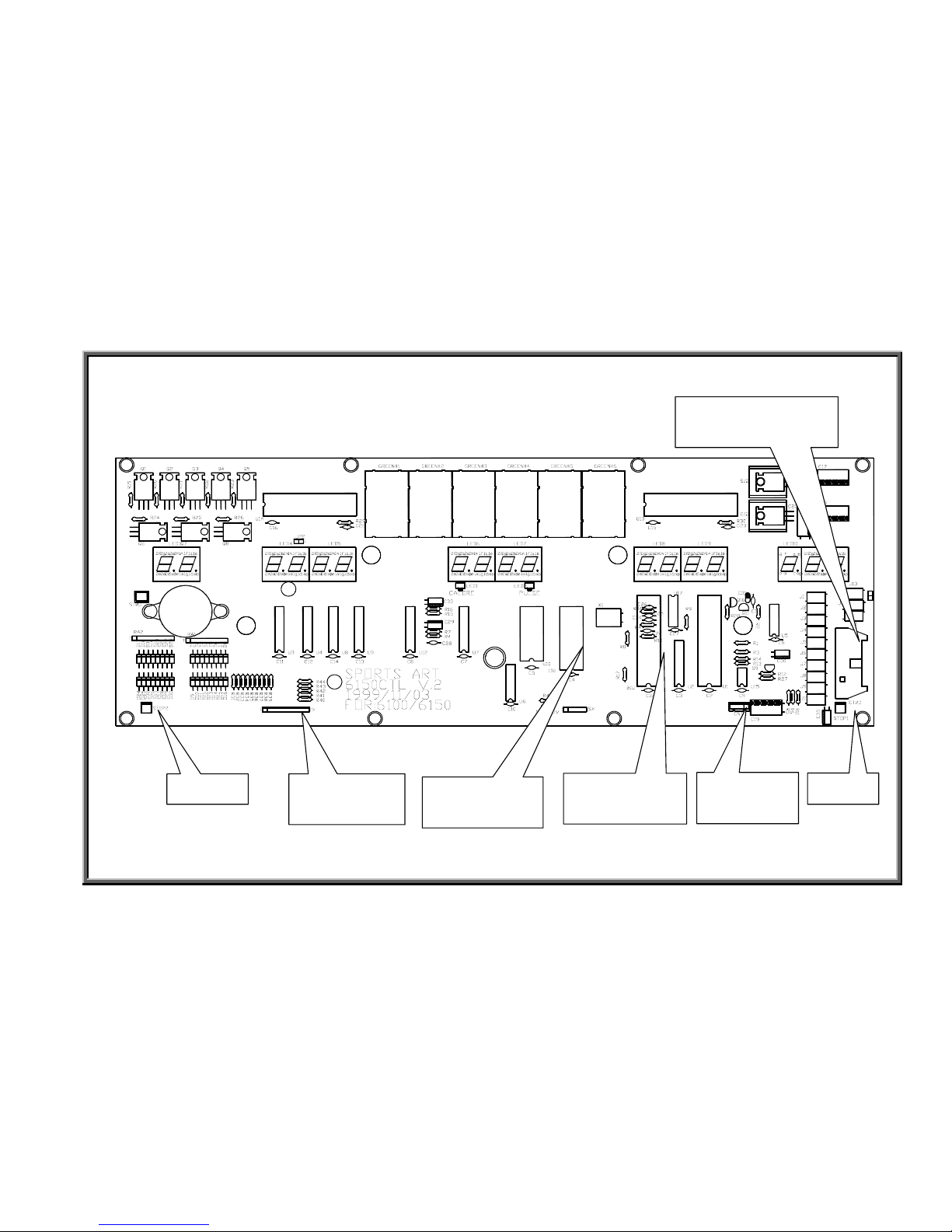
6150/E/6100/E Display Board Component Placement Diagram
1-6-1
CNT3 16-PIN
Cable Connector
STOP1
CNT1
Heart Rate
U16
Motor Program
U11
Main Program
K1, K2
Soft Keys
STOP2

SPORTS ART INDUSTRIAL CO., LTD.
6150/E/6100/E Drive Board Component Placement Diagram
1-7-1
EMG LED
Incline UP LED Incline DN LED
Incline ERR
LED
POWER LED
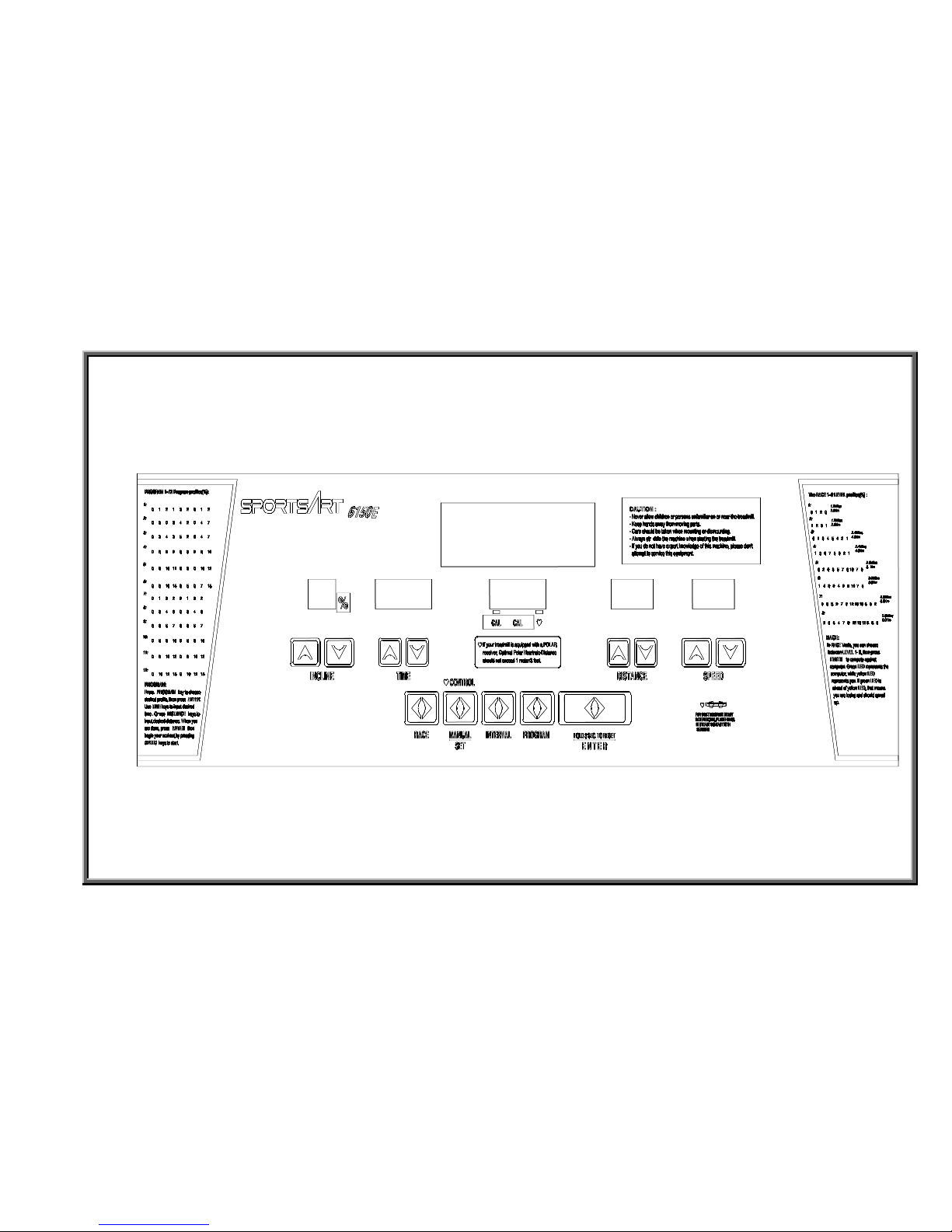
SPORTS ART INDUSTRIAL CO., LTD.
6150/E Display Panel
1-8-1
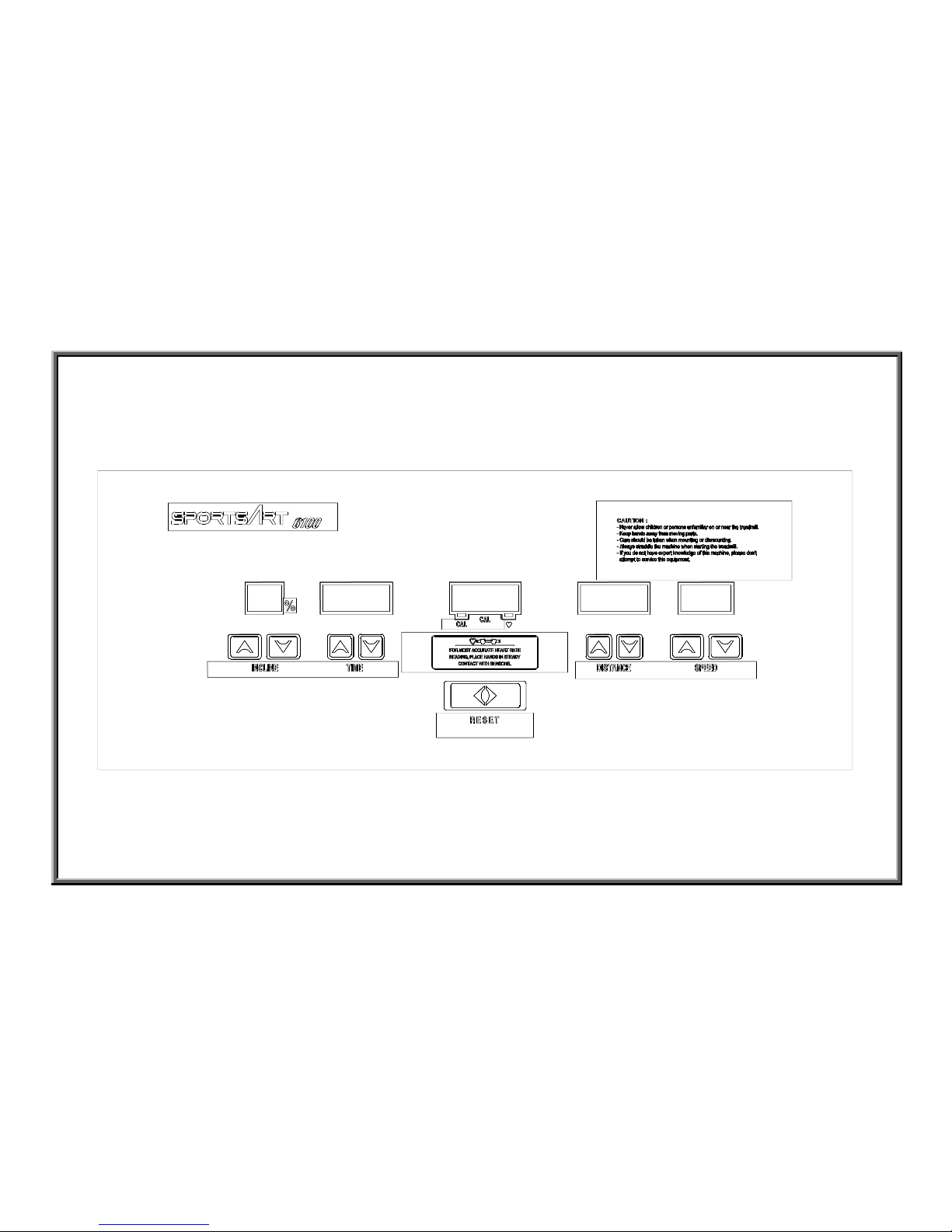
SPORTS ART INDUSTRIAL CO., LTD.
6100/E Display Panel
1-9-1

6100/E/6150/E
2. Operation
SPORTS ART INDUSTRIAL CO., LTD.

6100/E/6150/E
2. Operation
SPORTS ART INDUSTRIAL CO., LTD.
SPORTS ART INDUSTRIAL CO., LTD.
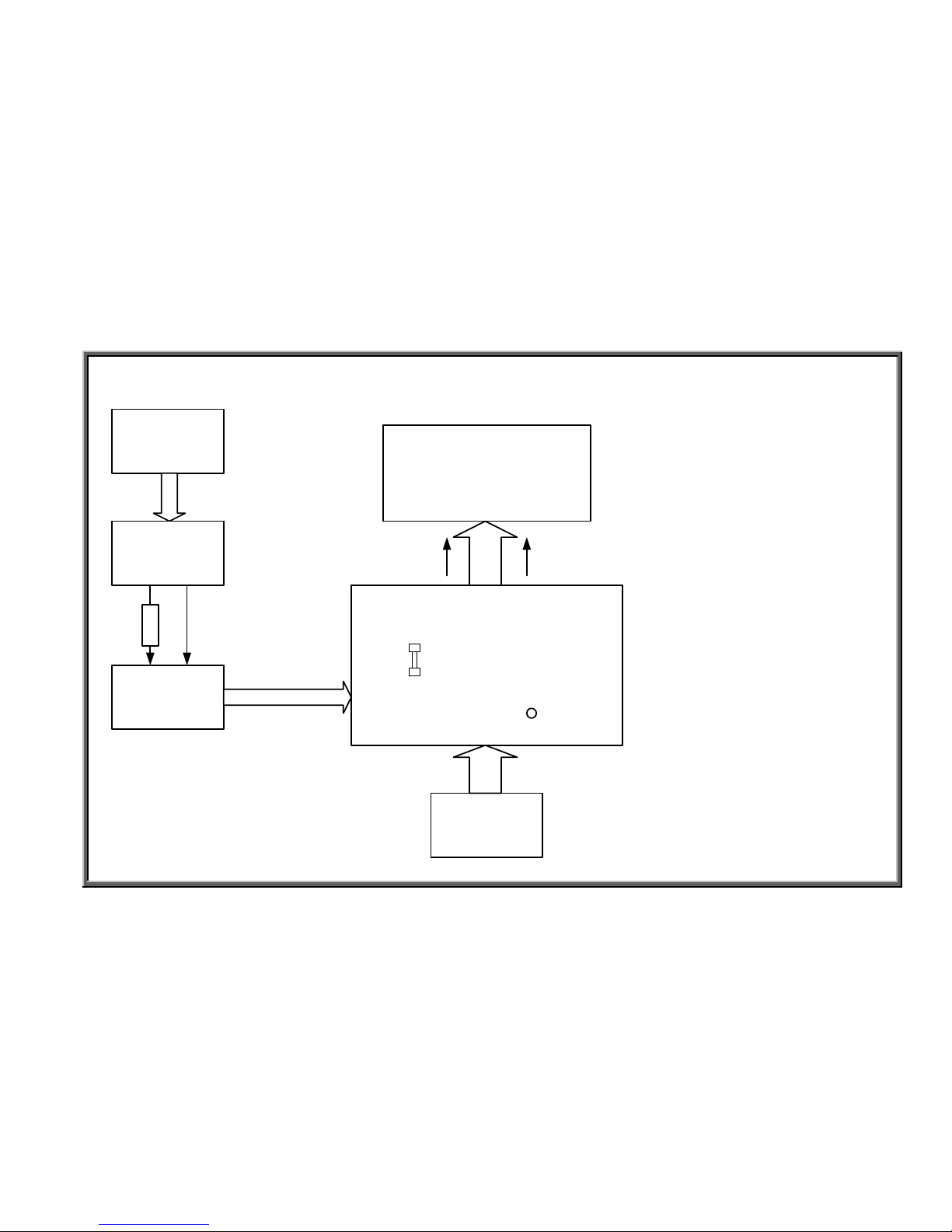
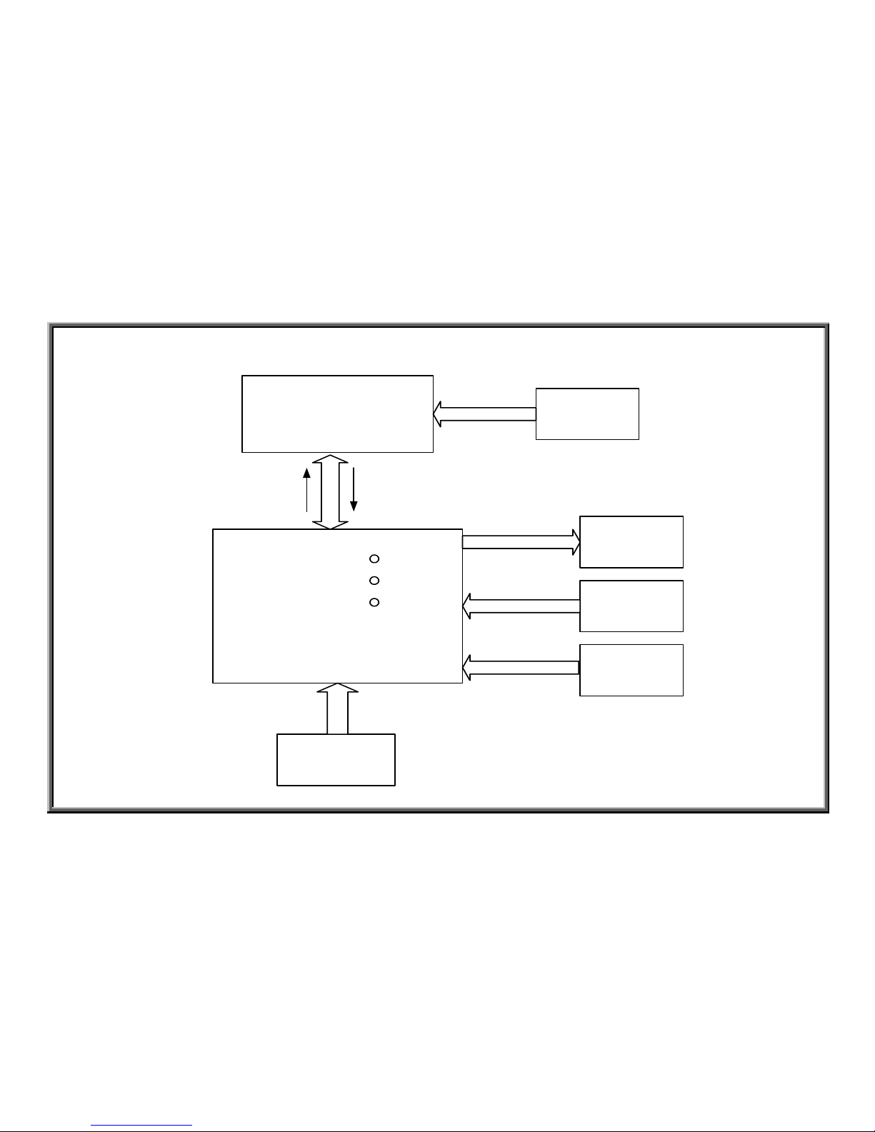
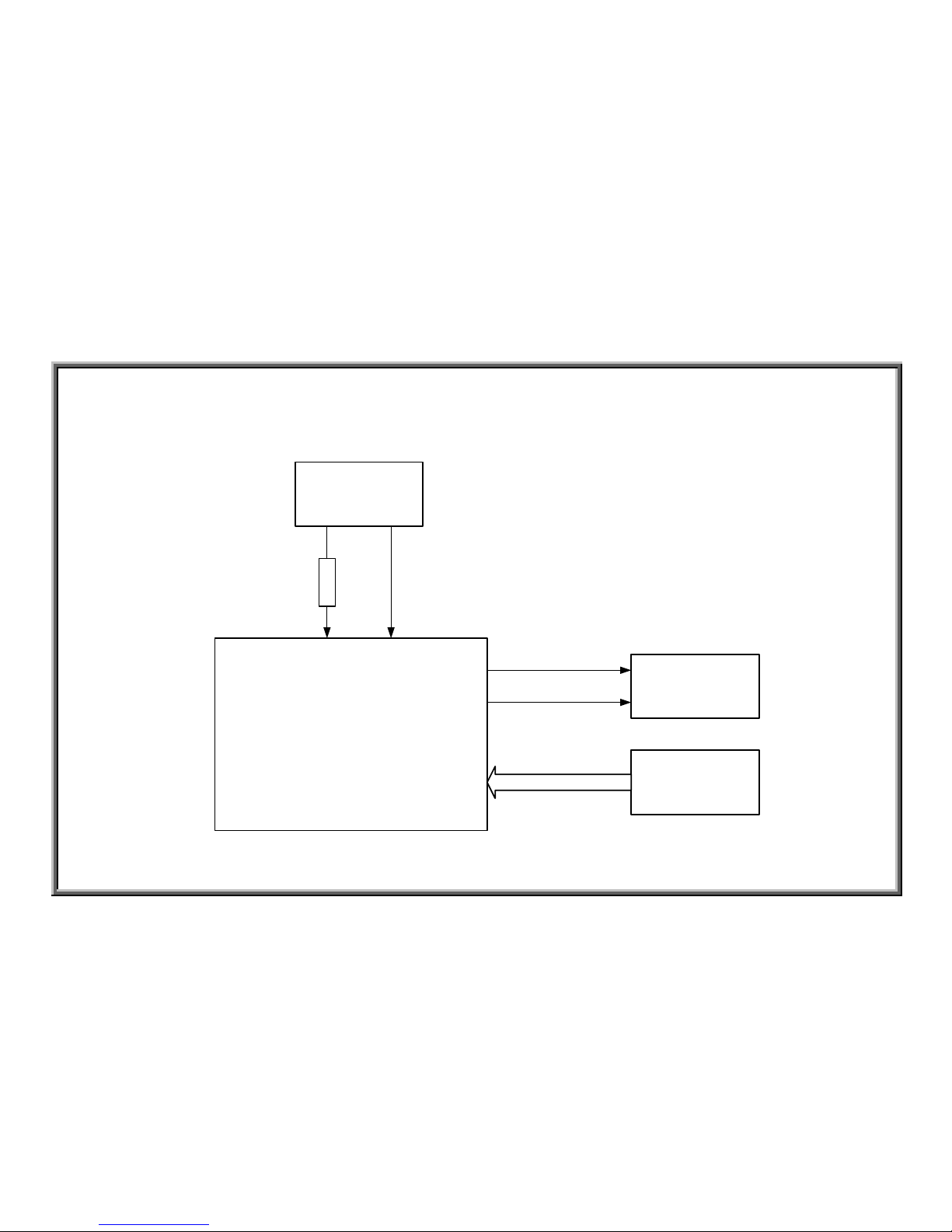
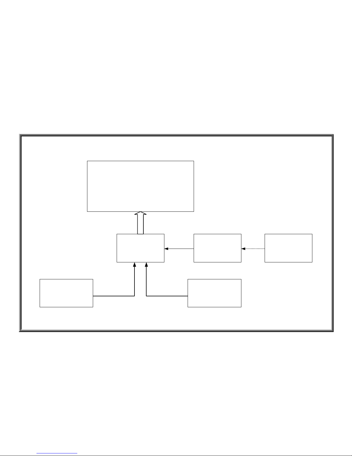
6150/E/6100/E Voltage Flow Chart
1. Configuration
DISPLAY BOARD
DRIVE BOARD
TRANSFORMER
POWER CORD
POWER
VBB 12VVCC 5V
FILTER
(CE)
ON/OFF
SWITCH
FUSE
AC1,AC2
VAC
F1
2-1-1
SPORTS ART INDUSTRIAL CO., LTD.
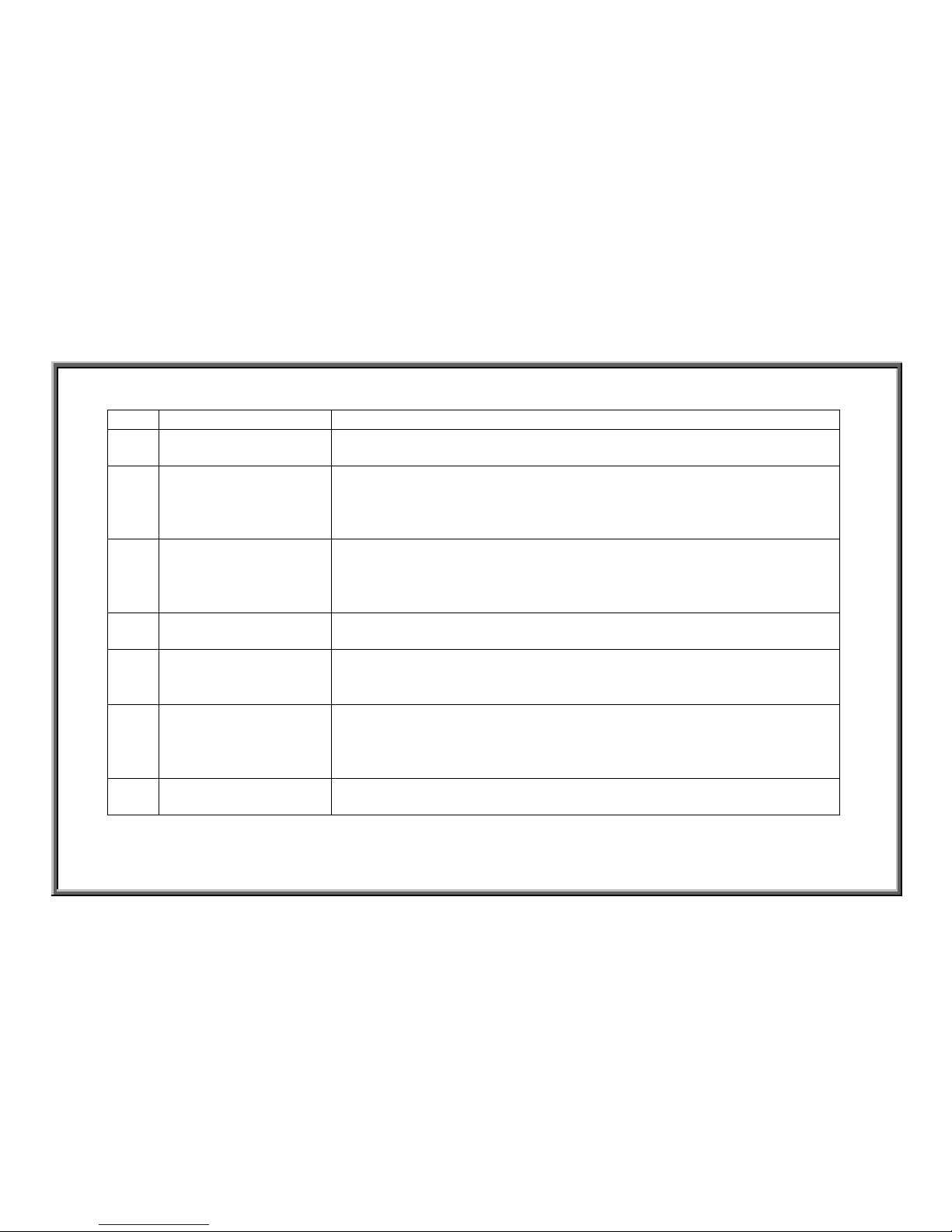
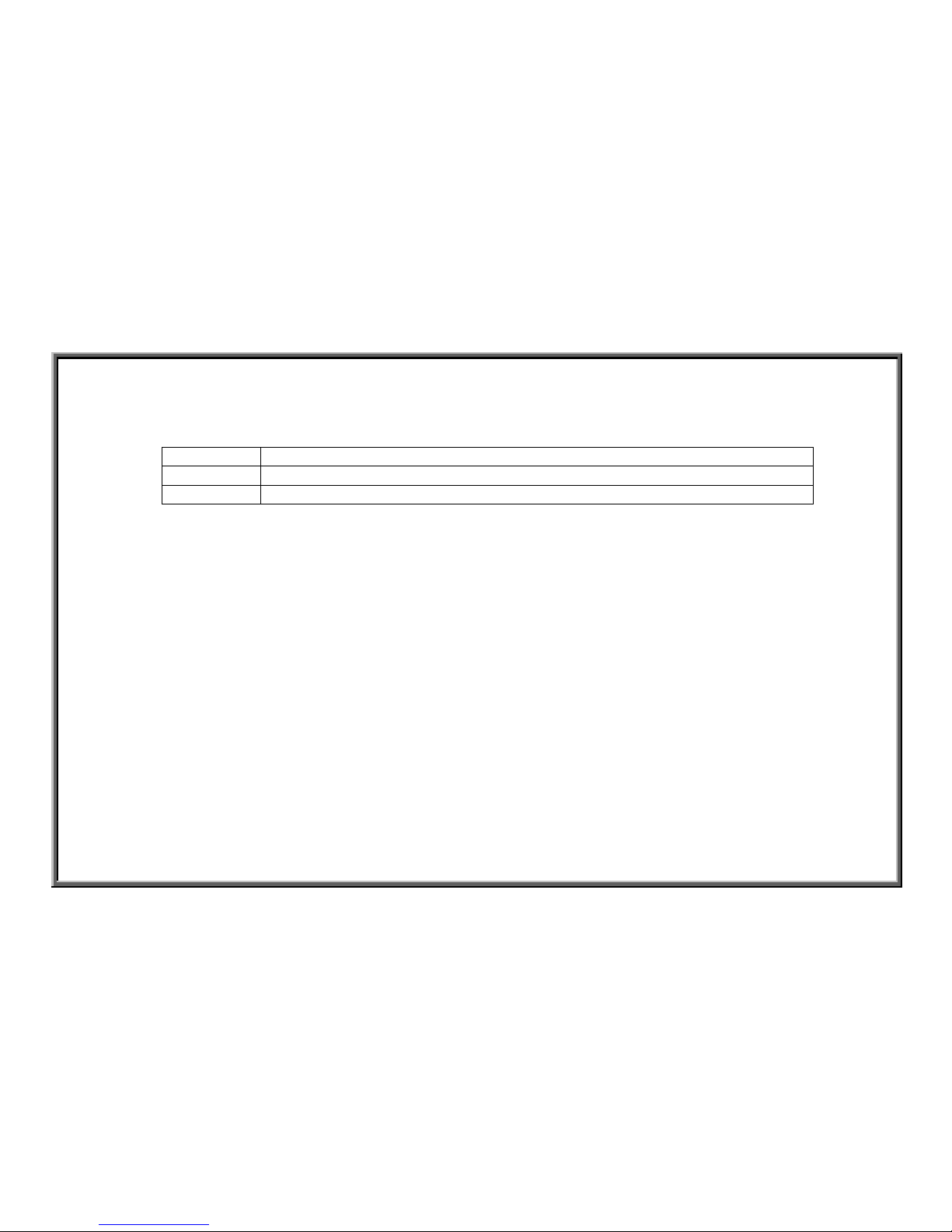
2. How the Unit Operates
Order Name Operation
1 Power Cord 1. Brings power in from the power supply.
2 Filter 1. Filters power, preventing interference (220V CE products only).
3 Fuse 1. Prevents damage to components from high current.
4 Power Switch 1. Turn power on “1”; power switch lights; power comes from the
filter into the unit.
2. Turn power off “0”; power switch doesn’t light; power doesn’t
come from the filter into the unit.
5 Drive Board 1. Drive board has sent AC power through the fuse F1 to the
transformer connector.
2. After the transformer power enters the drive board, the power is
stabilized as VCC, VBB, which supplies drive and display board
power.
3. VCC and VBB power go through the 16-PIN cable to the display
board.
6 Transformer 1. Takes power voltage from high volt AC1, AC2 to low voltage,
supplying power to components.
7 Display Board 1. VCC and VBB power are supplied to the display board CPU to
activate the unit.
2. The display windows light up once it has power.
2-1-2
SPORTS ART INDUSTRIAL CO., LTD.
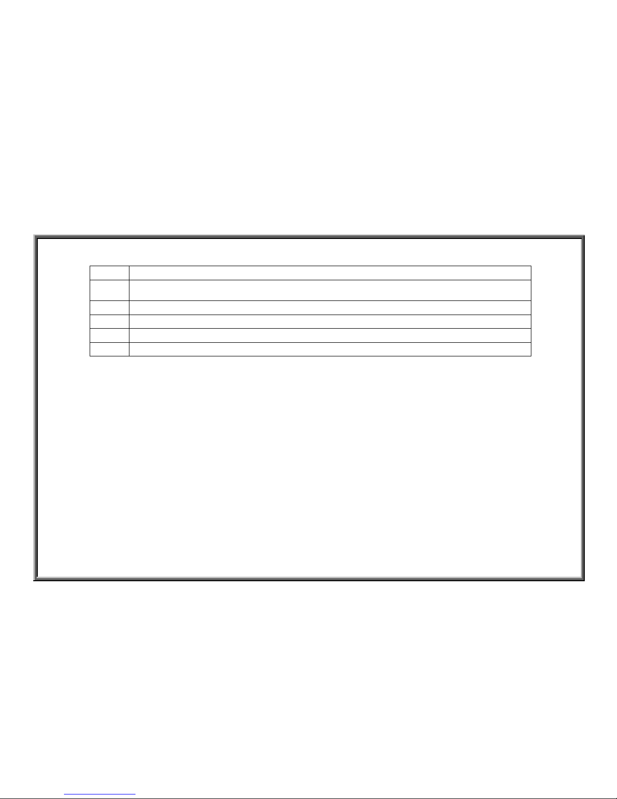
3. Operational Procedure
Step Operation
1
Plug unit into power supply.
2
Turn on power, flipping switch to ”1”; power light lights.
3
Drive board POWER LED lights.
4
Display board screen shows ”MAN’L”.
5
Turn off power switch, flipping switch to ”0”; power light doesn’t light; display
doesn’t light.
2-1-3
SPORTS ART INDUSTRIAL CO., LTD.
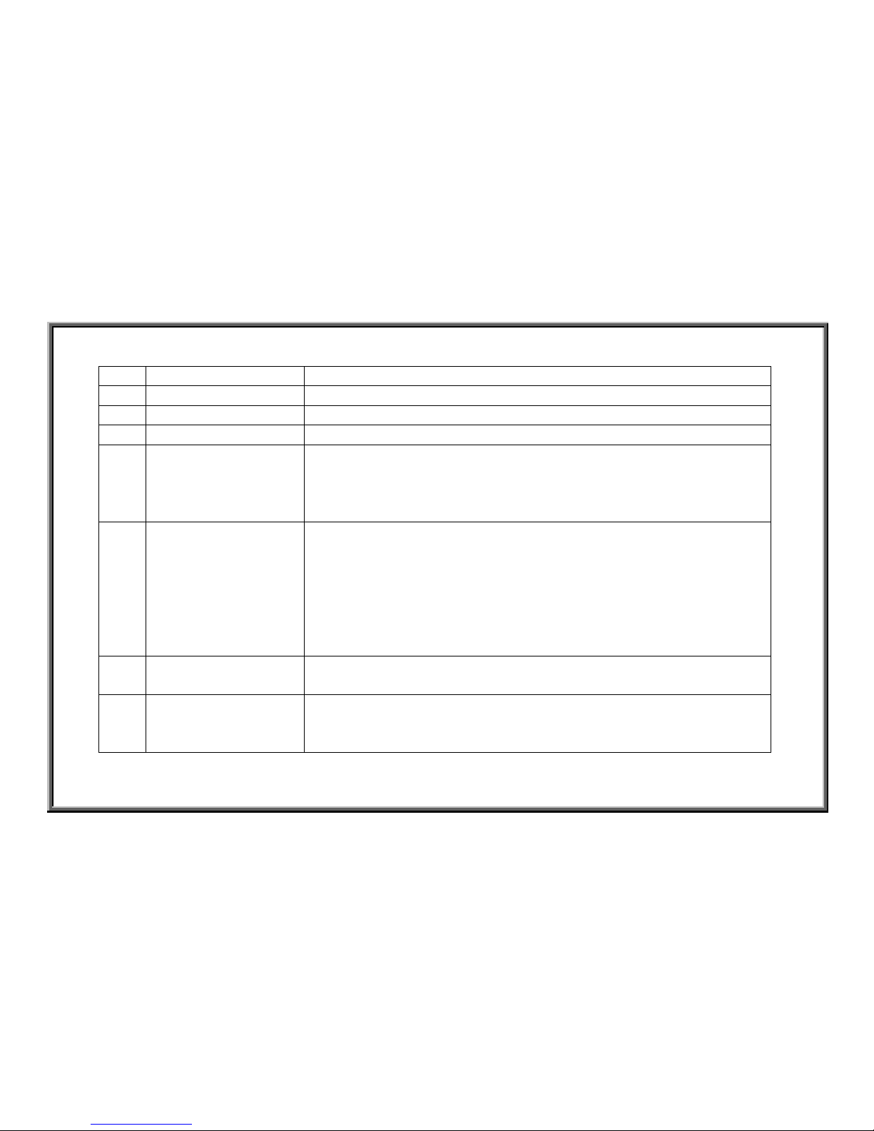
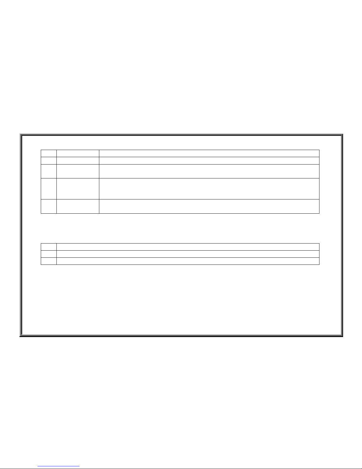
6150/E/6100/E Motor Operation Flow Chart
1. Configuration
4pin
Display Board
Drive Board Motor
Optic Sensor
2 pin
CLK
Motor Speed
Signal
Motor
Voltage
Optic Sensor Signal
Optic Sensor
Signal
Soft Keys
16 PIN
Key Signal
2-2-1
SPOR TS AR T INDUSTRIAL CO., L TD.
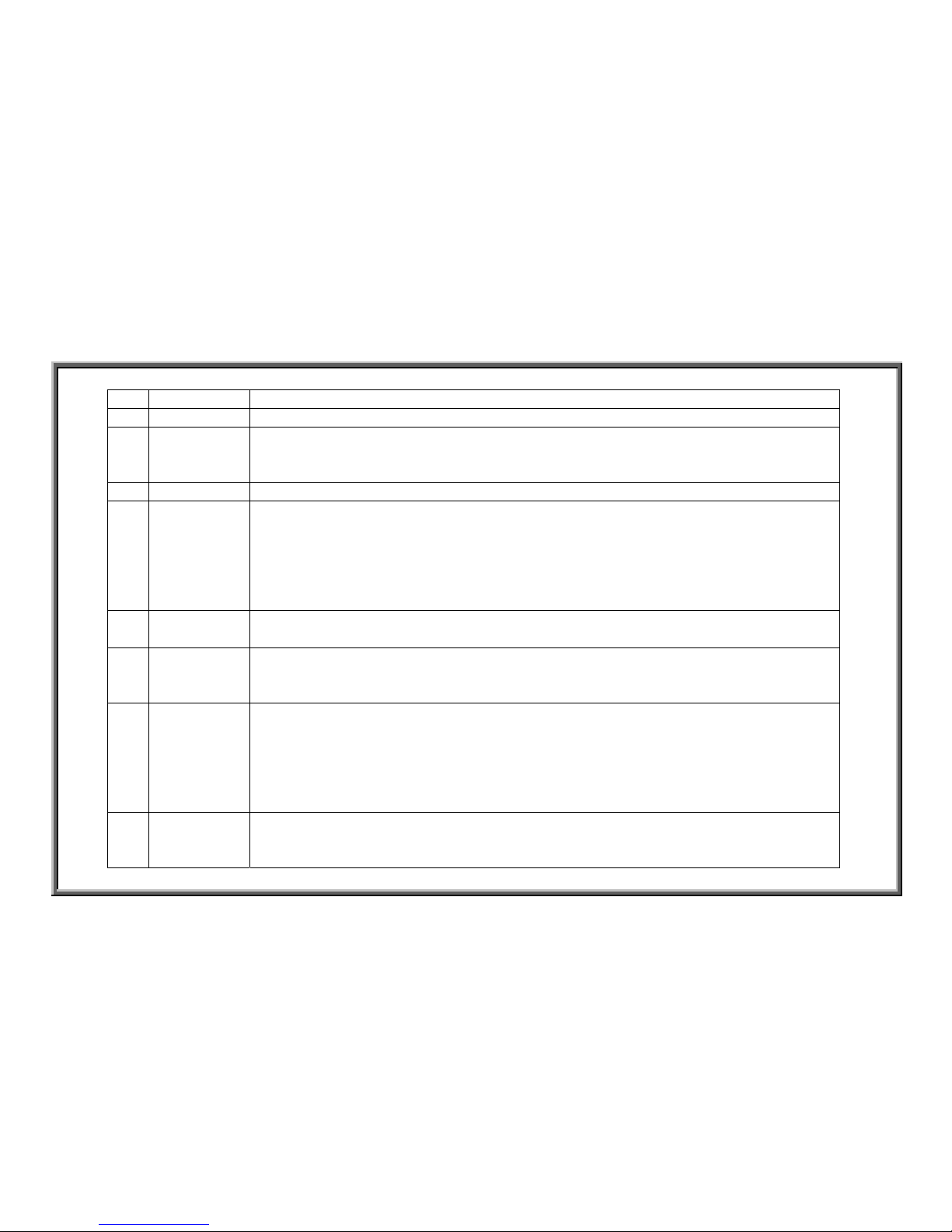
2. Operational Steps
Order Component Operation
1 Soft Keys 1.User inputs the desired speed.
2. Display board SPEED window shows SPEED key setting value.
2 Display Board 1. Display board CPU sends the motor speed signal to the drive board to
control motor speed.
2. The signal travels from the display board to the drive board through the
16-PIN cable.
3 Drive Board 1. Drive board translates the display board motor speed signal into the PWM
speed signal for the display board.
2. The PWM signal emits the drive board motor voltage to control motor
speed.
4 Motor 1.The motor rotates according to the drive board voltage.
2. After the motor operates, the rollers turn, moving the walking belt.
5 Tach Wheel; Optic Sensor 1. Motor operation moves the tachometer wheel.
2. The optic sensor detect the tachometer signal.
3. The signal travels the 4-PIN cable to the drive board.
6 Drive Board 1. The drive board translates the optic sensor signal from wave to rectified
form.
2. The drive board CLK indicator flashes or remains lit.
3. The optic sensor signal travels the 16-PIN cable to the display board.
7 Display Board 1. If the display board senses the optic sensor signal, it keeps emitting the
motor signal, allowing the motor to operate.
2-2-2
SPORTS ART INDUSTRIAL CO., LTD.
3. Operational Procedure
Step Operation
1
Press SPEED<▲> or SPEED<▼> key
2 Display board SPEED window setting speed value appears.
3 Motor starts operating; the tachometer wheel moves, and the treadmill belt rotates.
4 Drive board CLK indicator lights.
5 The display doesn’t show any error message; the motor continues to operate.
2-2-3
SPORTS ART INDUSTRIAL CO., LTD.
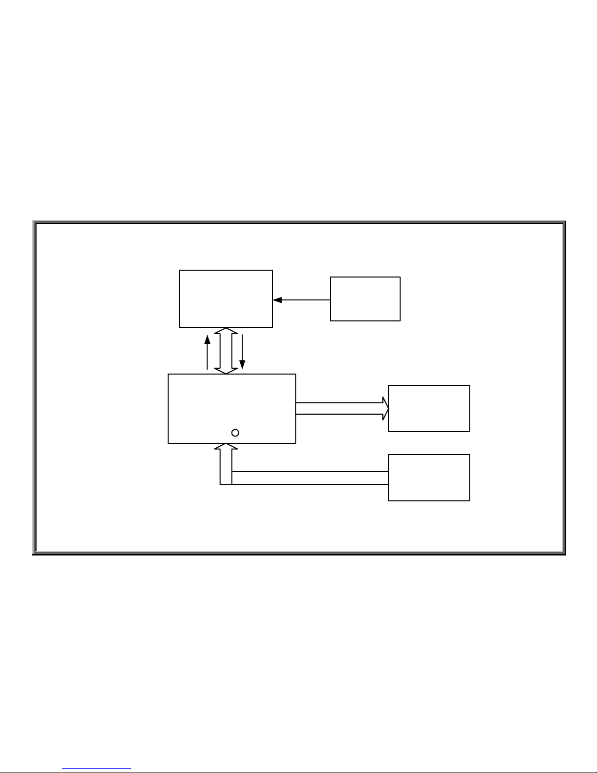
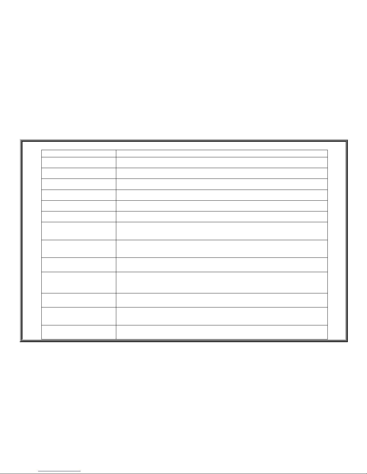
6150/E/6100/E Incline Operation Flow Chart
1. Configuration
Display Board
Drive Board
Transformer
UP
Incline Up/Down
Signal
Incline VR
Voltage; LIMIT
Signal
Transformer
Voltage
Incline
Motor
Incline VR
Set
Incline
LIMIT Switch
16 PIN
Incline
Motor
Voltage
Incline LIMIT
Signal
Incline VR
Voltage
DOWN
ERR
Soft Key
INC UP,DN
2-3-1
SPORTS ART INDUSTRIAL CO., LTD.
1. Operation
Order Part Operation
1 Soft Keys 1.User inputs incline height through the keys.
2 Display Board 1.The display board CPU sends the incline height setting signal to the drive board to
command incline action.
2.The signal travels from the display board through the16-PIN cable to the drive board.
3 Transformer 1.The transformer provides the incline motor with power to operate.
4 Drive Board 1.The drive board incline circuit operates according to the incline signal from the display
board.
2.By changing the polarity of the voltage, the drive board makes the DC incline motor turn
up or down.
3.The drive board UP indicator lights to indicate up incline action.
4
.The drive board DN indicator lights to indicate down incline action.
5 Incline VR Set 1. The incline gears turn, turning the VR, which increases or decreases the incline value.
2. Incline height is determined according to the incline VR value voltage.
6 LIMIT 1. When the incline motor leaves the incline VR value range, the incline VR gear hits the
LIMIT switch.
2. A broken LIMIT switch circuit means that the incline set has exceeded its range.
7 Drive Board 1.The incline LIMIT signal enters the drive board for processing. If the LIMIT switch
circuit is short (normal), then ERR indicator doesn’t light. If the LIMIT switch circuit is
broken (not normal), the ERR indicator lights.
2.If the ERR indicator lights, incline action immediately stops.
3.The incline VR wire VR value enters the drive board.
4.The incline LIMIT signal and VR value travels the 16-PIN cable to the display board.
8 Display Board 1.The display board senses the VR value and constantly emits the incline signal.
2. The signal is emitted until the incline VR value and the setting value are the same. Once
these are the same, the signal stops, and the incline action stops.
2-3-2

SPORTS ART INDUSTRIAL CO., LTD.
3. Operational Steps
Step Operation
1
Press the INCL<▲> or INCL<▼> key.
2 Display board INCL window shows incline value setting.
3 Drive board UP or DOWN indicator lights; ERR indicator doesn’t light.
4 Incline action begins.
5 Once the incline position is reached, action stops.
2-3-3
SPORTS ART INDUSTRIAL CO., LTD.
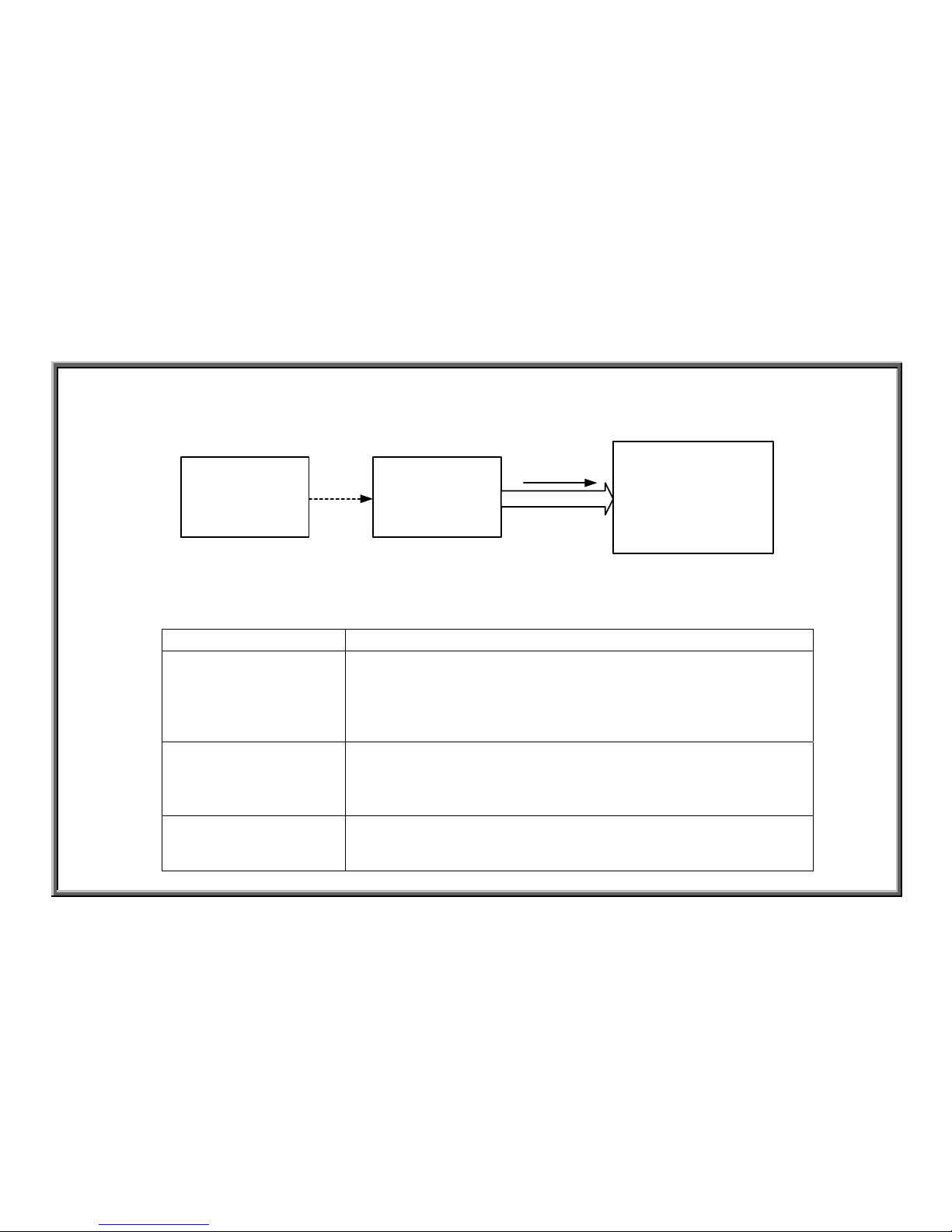
6150/E/6100/E Motor/Resistor Operation Flow Chart
1. Configuration
Drive Board
Motor
Big Resistor
FUSE
Optic Sensor
CLK
Motor Voltage
2-4-1
SPORTS ART INDUSTRIAL CO., LTD.
2. Operation
Order Name Operation
1 Motor 1. When the treadmill motor is operating, if the belt is pulled, the motor will speed up.
2 Optic Sensor 1. When the motor speeds up, the optic sensor signal speeds up.
2. The optic sensor signal travels the 4-PIN cable to the drive board.
3 Drive Board 1. When the drive board receives the optic sensor signal, if the signal and the setting differ,
the drive board creates a resistance signal and the drive resistance (large resistor)
operates.
4 Motor 1. When the resistor operates, the motor amp draw creates resistance.
2. If the user pulls the belt, the treadmill belt speed doesn’t increase; resistance is felt.
3. Operational Procedure
Steps Operation
1 Pulling the belt increases belt speed.
2 Resistance is created, and the treadmill belt speed is held steady.
2-4-2

SPORTS ART INDUSTRIAL CO., LTD.
6100/E/6150/E Display Key Function Flow Chart
1. Configuration
Display Board
Soft Keys
Key Signal
2. Operation
Name Operation
Soft Keys 1.Press the display soft keys.
2.The keys send their signal to the display board.
Display Board
1.The key signal is read by the CPU.
2. The CPU implements the key signal action.
2-5-1
SPORTS ART INDUSTRIAL CO., LTD.
3. Operational Steps
Key Operation
INCL<▲> key Continuously press INCL<▲> key; the INCL window value increases to 15.
INCL<▼> key Continuously press INCL<▼> key; the INCL window value decreases to 0.
TIME<▲> key Continuously press TIME<▲> key; the TIME window value increases to 99.00.
TIME<▼> key Continuously press TIME<▼> key; the TIME window value decreases to 0000.
DIST<▲> key Continuously press DIST<▲> key; the LOAD window value increases to 999.0.
DIST<▼> key Continuously press DIST<▼> key; the LOAD window value decreases to 0000.
SPEED<▲> key
Continuously press SPEED<▲> key; the SPEED window value increases to 20.0KPH
(16.0MPH).
SPEED<▼> key
Continuously press SPEED<▼> key; the SPEED window value decreases to 0.2KPH
(0.1MPH).
<RACE> key
Continuously press <RACE> key; the main display window shows “LEVEL
1”-“LEVEL 8”.
<MANUAL/SET> key
Continuously press <MAN’L> key; the main display window:
(1) switches between “MAN’L”/”SET” notices (No HRC function units)
(2) switches between “MAN’L”/”SET”/”HRC” (HRC function units)
<INTERVAL> key Continuously press <INTV> key; the main display window switches between
“INTV1”/”INTV2” notices.
<PROGRAM> key
Continuously press <PROG> key; the main display window shows “PRO 1”
-”PRO12” in order.
<RESET> key
Continuously press <RESET> key three seconds; the display beeps; the main display
w
indow shows; the small window deletes to 0.
2-5-2
SPORTS ART INDUSTRIAL CO., LTD.
6100/E/6150/E POLAR Heart Rate Operation Flow Chart
1. Configuration
Display Board
POLAR
Heart Rate
Receiver
3 PIN CABLE
PULSE
Heart Rate
Transmitter
2. Operational Procedure
Part Operation
Heart Rate Transmitter 1. Put on the POLAR transmitter.
2. The POLAR transmitter senses the wearer’s heart beat and transmits
the heart rate to the receiver.
3.POLAR heart rate transmitter transmits within a distance of 90
centimeters.
POLAR Heart Rate
Receiver
1.POLAR receiver receives the signal from the transmitter through a
wireless transmission.
2. After the heart rate signal is processed, it travels the 3-PIN cable to the
display board.
Display Board
1.After receiving and processing the heart rate signal, it is sent to the
program which then determines the heart rate value.
2. The display board PULSE window shows the heart rate value.
2-6-1
SPORTS ART INDUSTRIAL CO., LTD.
3. Operational Procedure
Step Operation
1 Put on the POLAR transmitter; stand on the treadmill.
2 Within 5 seconds, the PULSE window shows the heart rate value.
2-6-2
SPORTS ART INDUSTRIAL CO., LTD.
6100/E/6150/E Display Board HTR Heart Rate Flow Chart
1. Configuration
Display Board
HTR Board
HTR Handlebar
(left)
HTR Handlebar
(Right)
Heart Rate
Signal
HTR Handlebar
Signal
POLAR Receiver
POLAR
Transmitter
HTR Handlebar
Signal
2-7-1
 Loading...