

SportsArt Fitness 5100, 5150, 5200 Troubleshooting Manual

5100/5150/5200 Bicycle Troubleshooting Manual
Version 2; Date: 10-25-04

SportsArt 5100/5150/5200 Bicycle Troubleshooting Manual
5100/5150/5200 Bicycle Troubleshooting Manual
This manual was designed as a troubleshooting guide for technicians in the field. If you have suggestions
or comments, please contact Bob Baumgartner at bob@sportsartamerica.com
. Thank you!
Version 1: June 11, 2002
Version 2: Oct. 25, 2004 – Updated to include 5150.
Note on Design Changes:
The 5100 and 5150 are very similar. The 5150 was a revision of the 5100. The revision was made in the
spring of 2002 mainly for aesthetic reasons. The 5100 had legs that extended in back from a round,
plastic case. These legs and the case, shown on page 1-1-1, were eliminated on 5150, and the drive
board and battery were placed under the main covers. The rear feet on the 5150 extend from a tube
like that shown on the 5200 on page 1-1-2. The 5100 and 5150 displays also differ in appearance.
Functions, except for minor program modifications, are the same.
In the summer of 2003, the 5150 and 5200 displays were changed. Models with the new displays
were called C5150 and C5200 to match the new C-series bikes. Program operation differs from
earlier models because the display key layout changed considerably.
0-0-0

SportsArt 5100/5150/5200 Bicycle Troubleshooting Manual
Table of Contents
Chapter 1. Basic Configuration Diagrams
1-1-1 5100 Bicycle Electronic Component Placement Diagram
1-1-2 5200 Bicycle Electronic Component Placement Diagram
1-2-1 5100/5150/5200 Basic Configuration Diagram
1-3-1 5100/5150 Display Board Wiring Connection Diagram
1-4-1 5100/5150/5200 Drive Board Wiring Connection Diagram
1-5-1 5100/5200 Wire Hub Connection Diagram
Chapter 2. Operation Flow Charts
2-1-1 5100/5150/5200 Battery Switch Operation Chart, Cont. 2-1-2
2-2-1 5100/5150/5200 Generator Voltage Operation Chart, Cont. 2-2-2
2-3-1 5100/5150/5200 RPM Process Flow Chart, Cont. 2-3-2
2-4-1 5100/5150/5200 Resistance Operation Flow Chart, Cont. 2-4-2
2-5-1 5100/5150/5200 Display Keypad Function Flow Chart, Cont. 2-5-2
2-6-1 5100/5150/5200 POLAR Heart Rate Operation Flow Chart, Cont. 2-6-2
2-7-1 5100/5150/5200 HTR Operation Flow Chart
2-8-1 5100/5150 Remote Control Function Flow Chart, Cont. 2-8-2
0-0-1

SportsArt 5100/5150/5200 Bicycle Troubleshooting Manual
Table of Contents
Chapter 3. Test Configurations
3-1-1 5100/5150/5200 Testing the Generator, Cont. 3-1-2
3-2-1 5100/5150/5200 Testing the Battery, Cont. 3-2-2
3-3-1 5100/5150/5200 Testing the Electro-Magnet, Cont. 3-3-2
3-4-1 5100/5150/5200 Testing Resistance Voltage at the Drive Board, Cont. 3-4-2
3-5-1 5100/5150/5200 Testing the Infrared Optic Sensor, Cont. 3-5-2
3-6-1 5100/5150/5200 Testing the POLAR Heart Rate, Cont. 3-6-2
3-7-1 5100/5150/5200 Testing the HTR Board, Cont. 3-7-2
3-8-1 5100/5150/5200 Testing the Remote Receiver, Cont. 3-8-2
3-9-1 5100/5150/5200 Testing the Display Board VCC Voltage, Cont. 3-9-2
3-10-1 5100/5150/5200 Testing the Drive Board VCC Voltage, Cont. 3-10-2
3-11-1 5100/5150/5200 Testing the Drive Board Power Transistor, Cont. 3-11-2
0-0-2

SportsArt 5100/5150/5200 Bicycle Troubleshooting Manual
Chapter 1. Basic Configuration Diagrams
1-0-0
SportsArt 5100/5150/5200 Bicycle Troubleshooting Manual
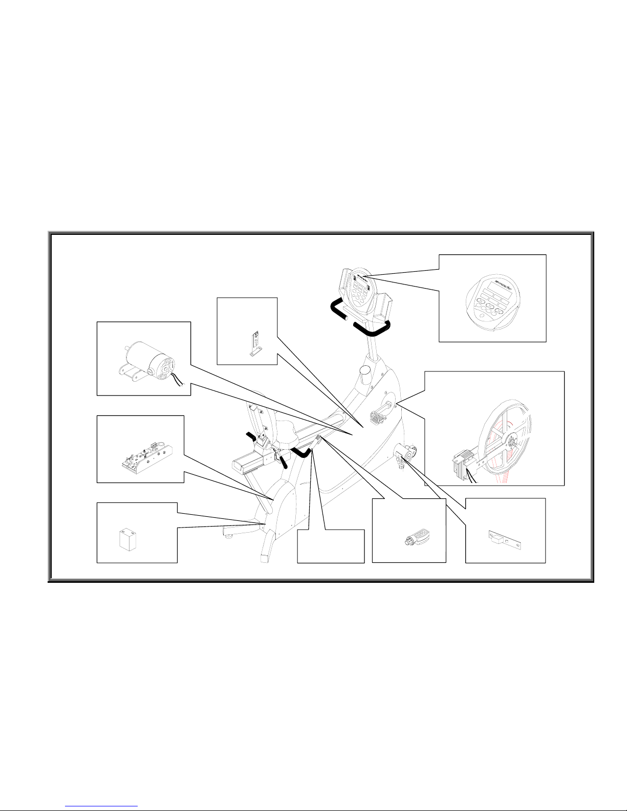
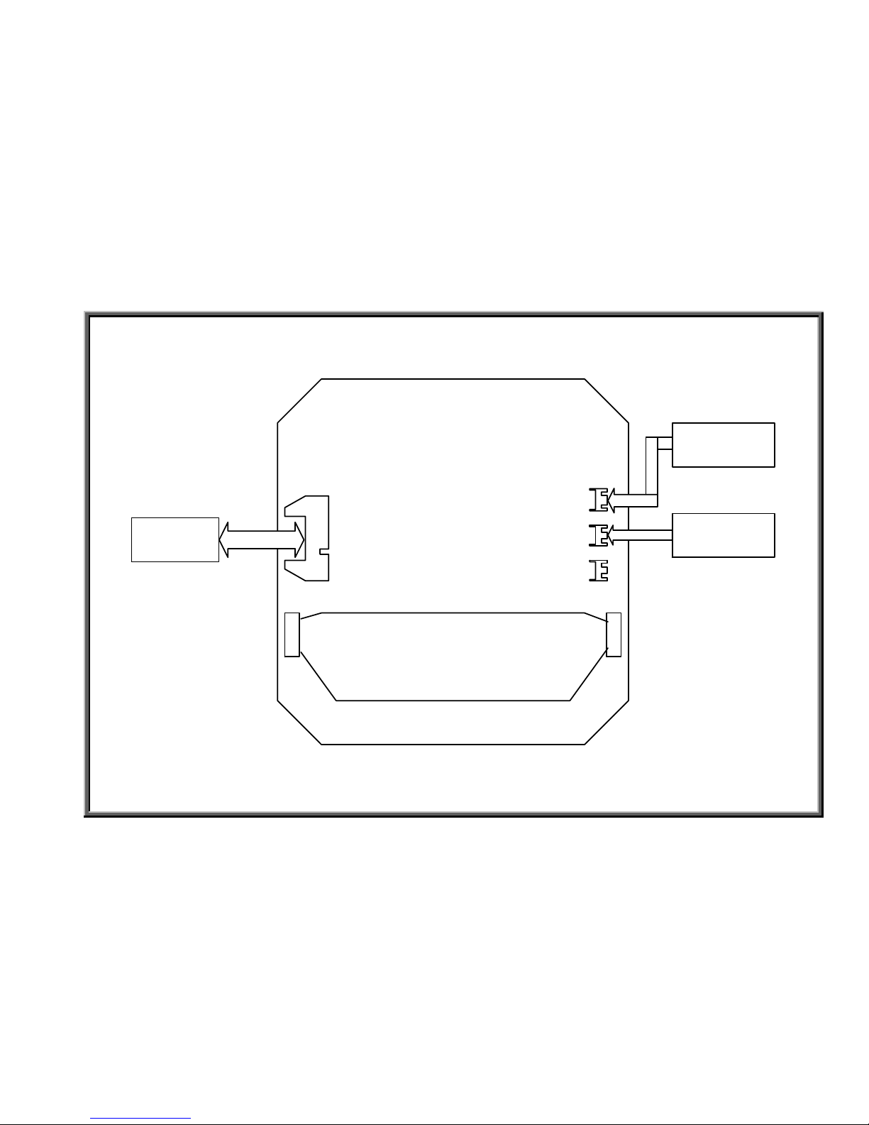
5100 Bicycle Electronic Component Placement Diagram
1-1-1
Display Panel
HTR
Handlebar
Drive Board
Flywheel and
Magnet
Optic
Sensor
Battery
Remote
Receiver
Remote
Transmitter
Generator
SportsArt 5100/5150/5200 Bicycle Troubleshooting Manual
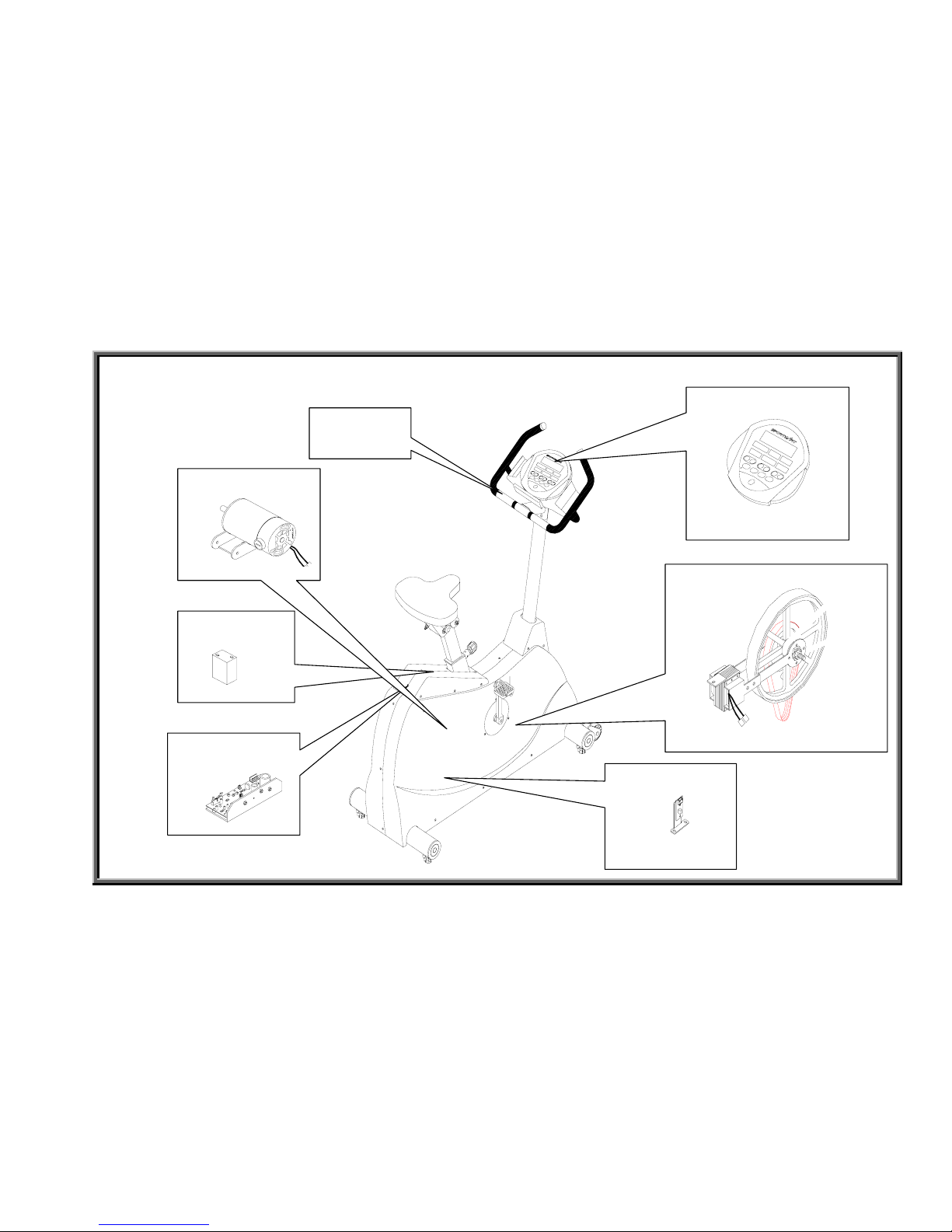
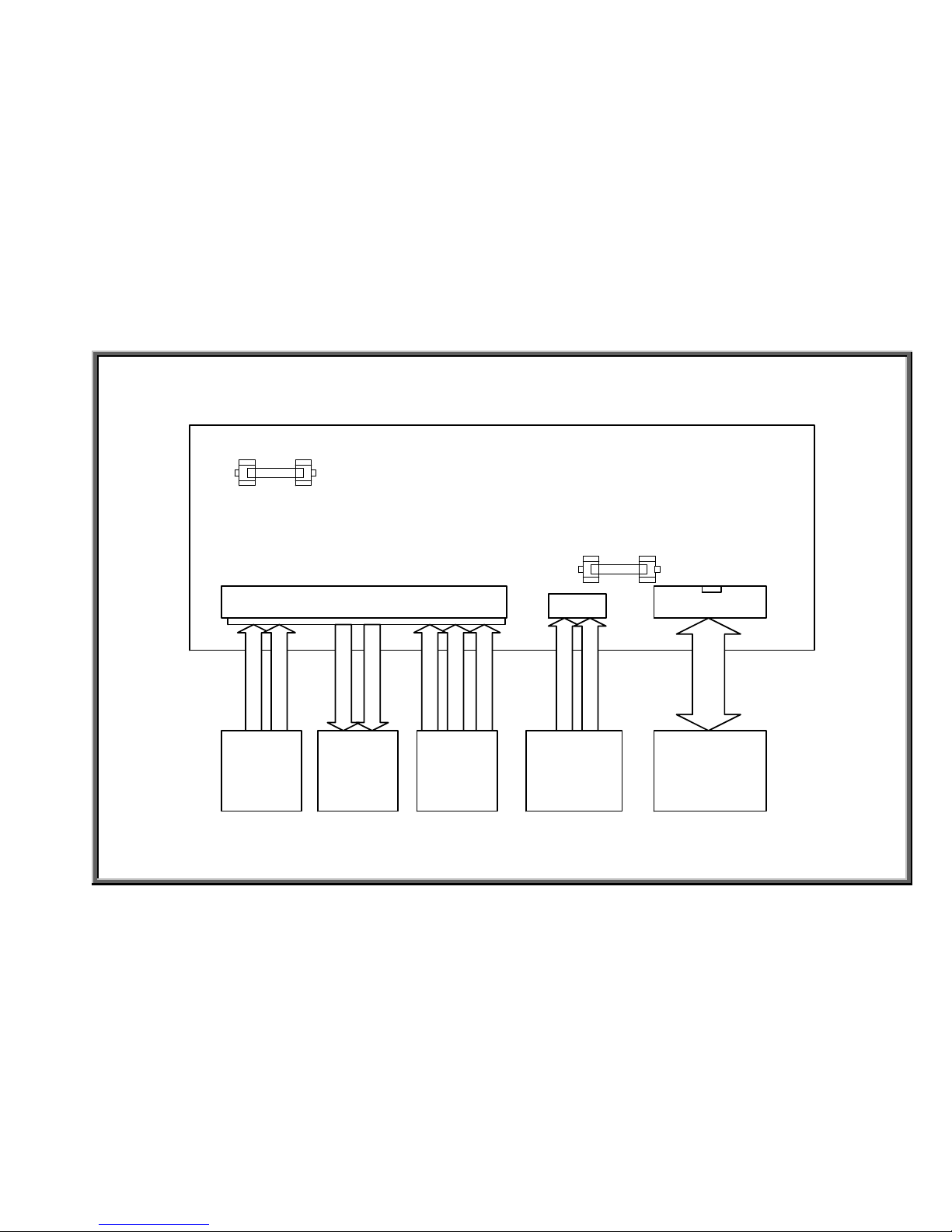
5200 Bicycle Electronic Component Placement Diagram
1-1-2
Display Panel
HTR
Handlebar
Drive Board
Flywheel and Magnet
Optic Sensor
Battery
Generator
SportsArt 5100/5150/5200 Bicycle Troubleshooting Manual
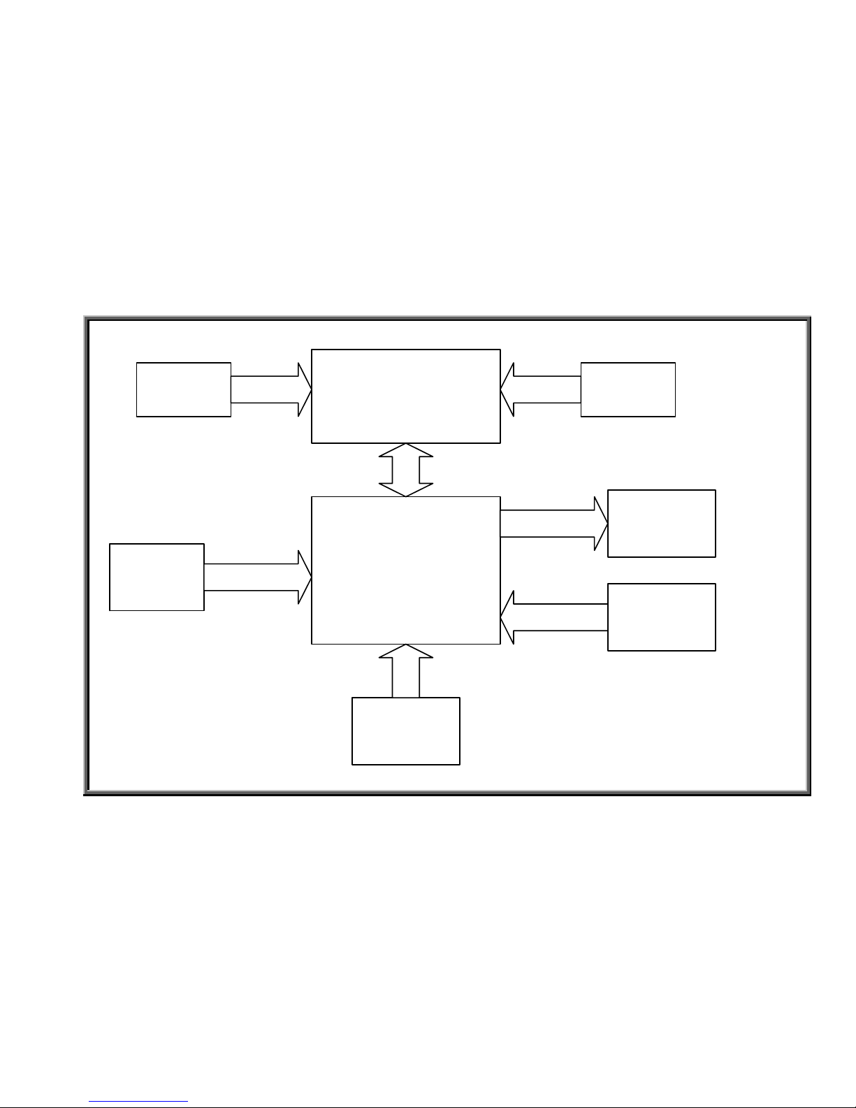
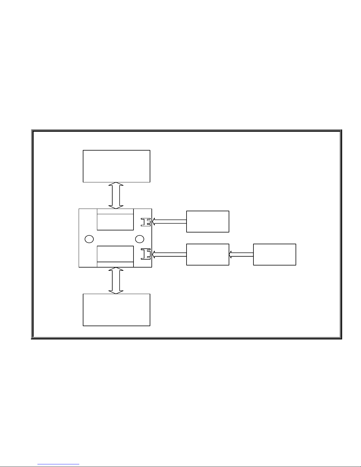
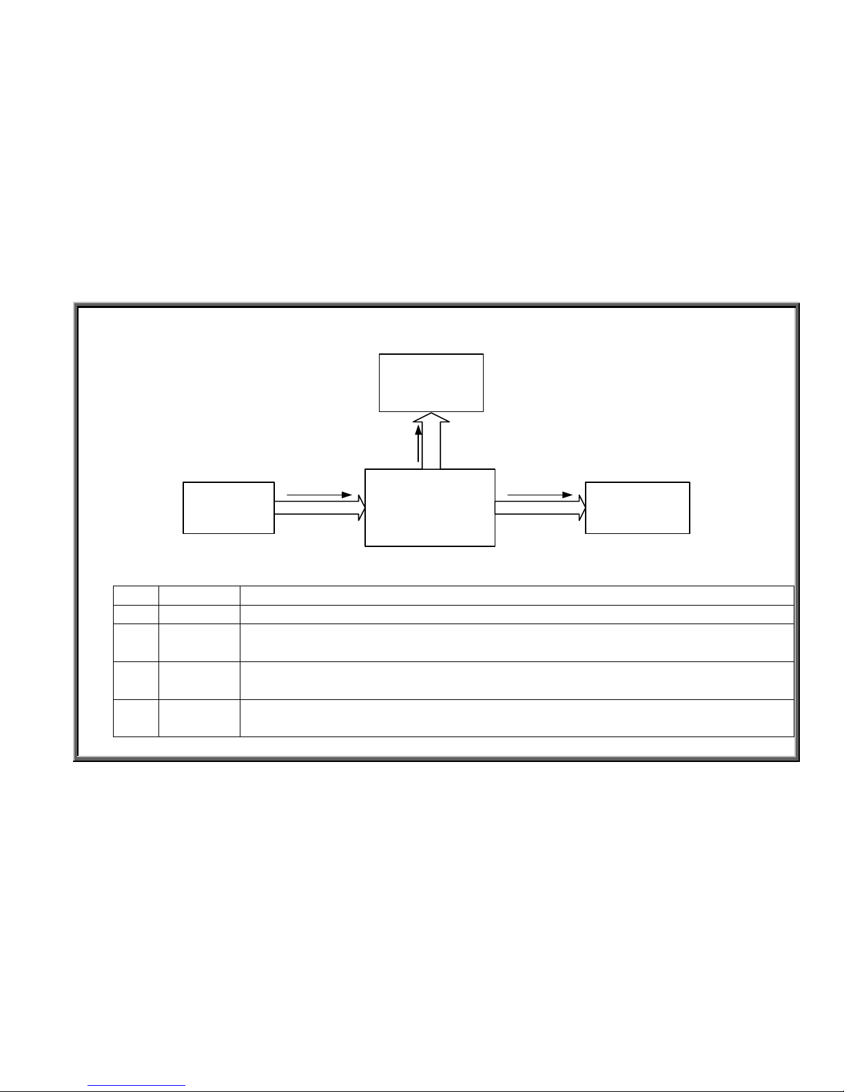
5100/5150/5200 Basic Configuration Diagram
Display Board
Drive Board
Generator
Optic Sensor
Magnet
Battery
16 PIN
CBALE
WHITE-BLACK
2 PIN
CABLE
BLUE-BLUE
RED-YELLOW-
BLACK
Remote
Control/
Transmitter
Heart Rate
Board
3 PIN CABLE 3 PIN CABLE
1-2-1
SportsArt 5100/5150/5200 Bicycle Troubleshooting Manual
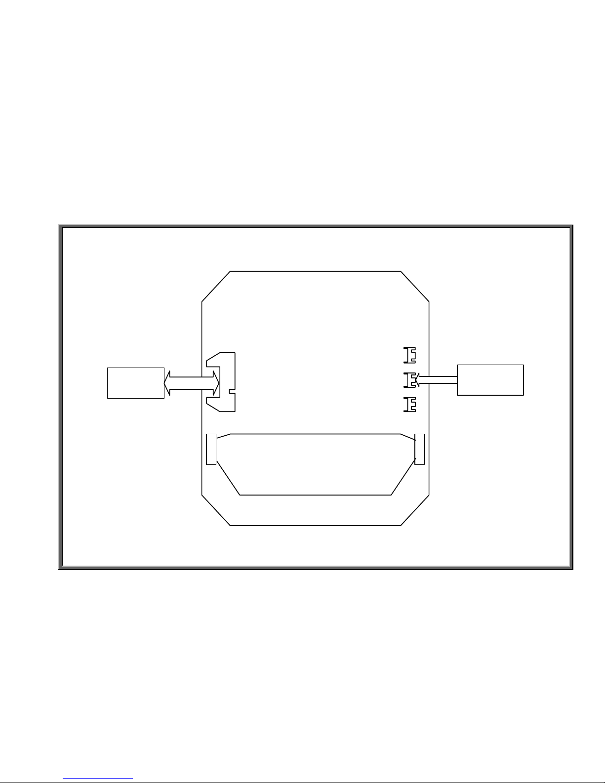
5100/5150 Display Board Wiring Connection Diagram
J2
J4
J5
POLAR Heart
Rate Board
3 pin cable
Drive Board
16 PIN CABLE
Soft Keys
CNT3
CNT2
1-3-1
SportsArt 5100/5150/5200 Bicycle Troubleshooting Manual
5200 Display Board Wiring Connection Diagram
J2
J4
J5
HTR Board
& HTR
Handlebar
POLAR Hear
t
Rate Board
3 pin cable
3 pin
Drive Board
16 PIN CBALE
Soft Keys
CNT3
CNT2
1-3-2
SportsArt 5100/5150/5200 Bicycle Troubleshooting Manual
5100/5150/5200 Drive Board Wiring Connection Diagram
CN3
CN2CN1
Display BoardBatteryGenerator Magnet
Infrared
Optical
Sensor
BALCK
WHITE
YELLOW
RED
BLUE
BLUE
BLACK
WHITE
WHITE
16 PIN CBALE
F1
F2
1-4-1
SportsArt 5100/5150/5200 Bicycle Troubleshooting Manual
5100/5150 Wire Hub Connection Diagram
CN1
CN2
TO CONTROL
TO DRIVER
CN4
CN3
HTR Board
Remote
Receiver
Drive Board
16 PIN
To Display Board
16 PIN
HTR HANDLE
BAR
1-5-1

SportsArt 5100/5150/5200 Bicycle Troubleshooting Manual
Chapter 2. Operation Flow Charts
2-0-0

SportsArt 5100/5150/5200 Bicycle Troubleshooting Manual
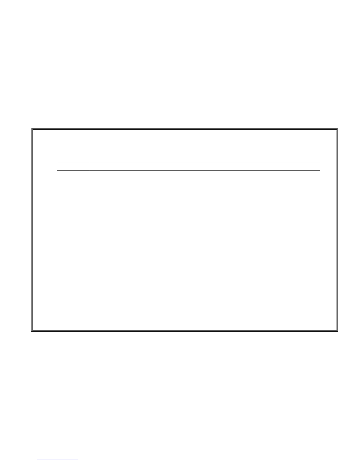
5100/5150/5200 Battery Switch Operation Chart
1. Configuration
Display Board
Drive Board
Battery
2 pin
V
Soft Keys
VCC
16 pin
ON
ON
2. Operation
Order
Item Operation
1 Battery 1. When the bicycle isn’t being ridden, drive board temporary power supply
allows the display board to light up.
2. Riding for 20 minutes recharges the battery.
2 Soft keys 1. When the unit is off, pressing the display board “ON” key sends a message
prompting the drive board to start unit operation.
3 Display board 1. The soft key “ON” signal is sent to the drive board.
4 Drive board 1. The “ON” signal sends the battery voltage to the drive board.
2. After stabilizing the battery voltage, the drive board provides power to the
display board, starting up the display.
5 Display board 1. After getting power, the display board beeps;
2. The display windows light and numbers appear.
2-1-1
SportsArt 5100/5150/5200 Bicycle Troubleshooting Manual
3. Operational Steps
Steps Operation
1 Display panel is inactive, dark.
2 Press the ON key.
3
1. Display panel beeps once. Main display shows “MAN’L”
2. Windows show “0”.
2-1-2
SportsArt 5100/5150/5200 Bicycle Troubleshooting Manual
5100/5150/5200 Generator Voltage Operation Chart
1. Configuration
Display Board
Drive BoardGenerator
2 pin
V
Battery
2 pin
VCC
Recharge
16 pin cable
2. Operation
Order
Item Operation
1 Generator 1. When the bike is ridden, the generator makes power.
2 Drive
Board
1. The generator provides voltage to the drive board.
3 Display
Board
1. The drive board VCC circuit provides power to the display board.
2. The display lights.
4 Battery 1. The drive board provides processed power from the generator to recharge the
battery.
2-2-1
 Loading...