

SportsArt Fitness 1060 Owner's Manual
FITNESS
1000
OWT,{ER,S
ASSEMBLY INSTRUCTIONS
MAT,{UAL
TABLE
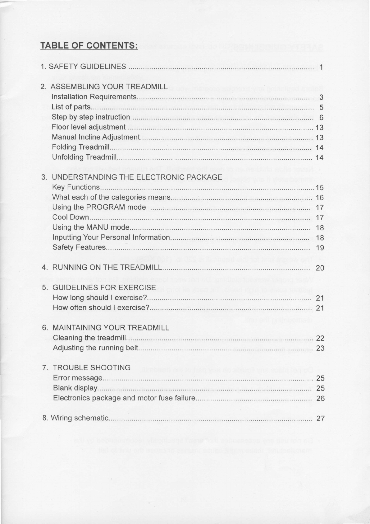
1. SAFETY GUIDELINES
OF CONTENTS:
2. ASSEMBLING
Installation Requirements.........
List
Step by
Floor level
Manual lnclineAdjustment...............
Folding Treadmill.
Unfolding Treadmill.
3. UNDERSTANDING
Key Functions.........
What
Using the PROGRAM mode ............ ........,........
Cool Down..............
Using
Inputting Your Personal lnformation........
Safety Features..
parts........
of
step
each of the categories means..... ...............
the
YOUR
instruction .......
adjustment
MANU mode.......
TREADMILL
THE
ELECTRONIC PACKAGE
.........
................
...............
................15
....
3
5
6
13
13
14
14
16
17
17
18
18
19
4. RUNNING
5, GUIDELINES FOR EXERCISE
How long should I exercise?
How
often should I exercise?
6. MAINTAINING YOUR TREADMILL
Cleaning
Adjusting
7. TROUBLE
Error message.
Blank
Electronics
8. Wiring schematic.
display.....
THE TREADMILL............
ON
the treadmi11.............. ............
the running be|t....... .............
SHOOTING
package
and motor fuse fai|ure..............
20
...............
..............
21
21
22
23
25
25
26
27
SAFETY GUIDELINES:
Please read and follow
Before
recommended that
.
.
.
.
.
beginning any exercise
you
Read
Assemble and operate
behind the treadmill clear.
Never allow children
immediately if any
Check the treadmill before every use.
nuts
in any way.
Keep hands
this owner's manual carefully and follow the instructions.
and bolts are tightened.
away
from
following
the
program, you
undergo a complete
the treadmill
on or
object becomes caught
near
Do
moving
parts.
safety
the treadmill.
not use the treadmill if the unit is
guidelines:
should
physical
on
a solid,
in
Make
consult
examination.
level
The running
the belt or rollers.
sure all
with
surface. Keep
belt will not
parts
are assembled,
your
doctor. lt
the area
stop
disassembled
is
and all
.
The weight limit for this
.
Wear
leather
.
Don't rock
dismounting the unit.
.
Straddle the machine with
starting the
.
Do not
.
To
switch away from water.
.
Turn
proper
place
prevent
off the treadmill
workout
soles or high
the unit
running
any liquids on any
shock, keep all electric components such as the motor, cord, and
heels. Tie
from
belt.
while
treadmill
clothing:
side to side. Care should be taken when mounting and
your
adjusting or
is 220 lb.
Do not wear loose
back all
feet on the
part
of the treadmill.
(100
KGS).
clothing. Do not wear shoes with
long hair.
right
and left staging
working near
rear roller.
the
platforms
before
.
Do not use any accessories that aren't specifically
manufacturer, these might cause injuries or cause the unit to fail.
recommended
by the
!
.
.
Work within
.
you
lf
your
The treadmill
precautions
pleasurable
feel
any
physician
is designed for
and using
exercise with
your
recommended
pain
or abnormal sensation,
immediately.
good
this treadmill.
exercise level,
your
use and enjoyment.
judgment
and common
NOT
do
STOP YOUR WORKOUT
sense,
work to exhaustion.
By following
you
the above
will enjoy
and
consult
safe and
2
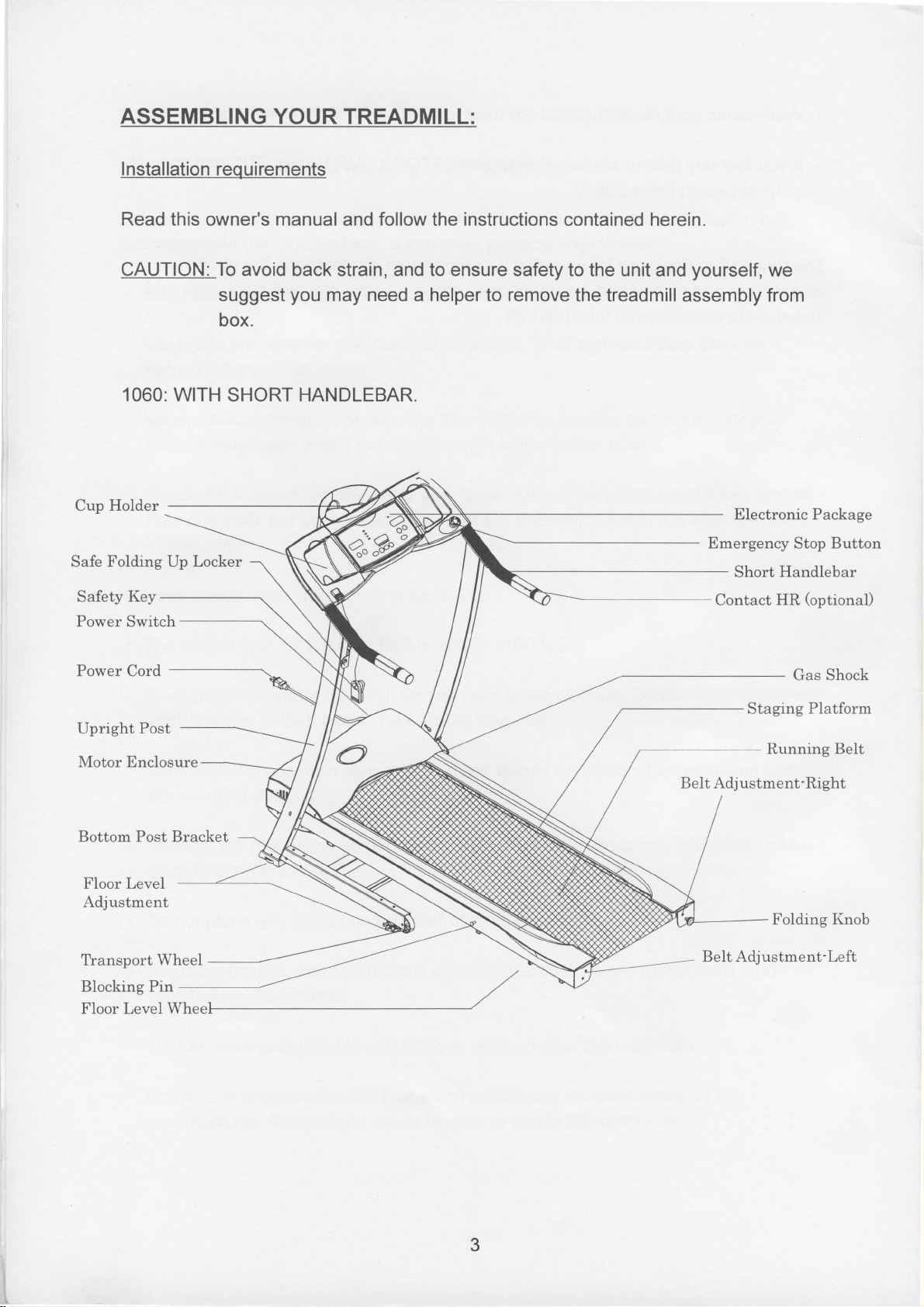
ASSEMBLING
YOUR TREADMILL:
I nstallation requirements
Read this owner's manual
CAUTION: To
1060:
Holder
Cup
Folding
Safe
Safety Key
Power Switch
Power
Cord
suggest
box.
WITH
Up Locker
SHORT HANDLEBAR.
and
follow
instructions
the
contained herein.
avoid back strain, and to ensure safety to the unit
you
may need a helper to remove
the treadmill
yourself,
and
assembly
Emergency
Contact
we
from
Electronic Package
Button
Stop
Handlebar
Short
(optional)
HR
Gas Shock
Upright
Motor Enclosure
Bottom Post Bracket
Floor Level
Adjustment
Tlansport
Blocking Pin
Floor Level
Post
Wheel
Whee
Staging
-
Adjustment-Right
Belt
Belt
Adjustment-Left
Platform
Running Belt
Folding
Knob
3
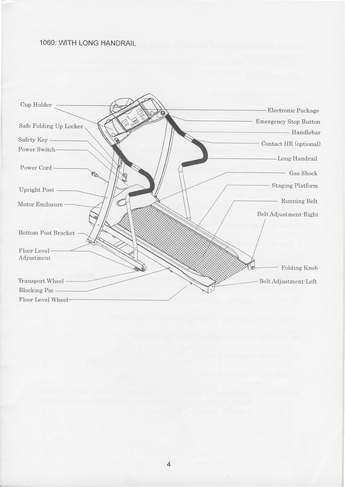
1060:
WITH
LONG
HANDRAIL
Cup Holder
Safe Folding
Safety
,
Power
Upright Post
Motor
Bottom
Floor
Adjustment
Power
Level
Key
Switch
Cord
Enclosure
Post
Up Locker
Bracket
Electronic
Emergency
Contact
Belt
HR
Long
Staging
Running
Adjustment'Right
Folding
Package
Stop Button
Handlebar
(optional)
Handrail
Gas Shock
Platform
Belt
Knob
Tlansport
Blocking
Floor
Level
Wheel
Pin
BeIt
Adjustment-Left
4
Before
assembling
following items:
your
treadmill. make
sure
that
you
have
all the
1060 List
1. Two floor
2. Eight 5/16" x314"
3. Eight
4. Three
Three
5.
Four
6.
7. Four
8. One
parts
of
level adjustments
5/16"
114" xL314"
1/4" washers-electronic
hex
washers-bottom
5/16" xL3l4" bolts-base
5/16" washers-base
Allen wrench-Smm
bolts
-
bottom
bolts-electronic
post
post
bracket
supporting frame
supporting frame
package
package
bracket
9. One hex Allen wrench
1 0. One fuse
11 .
Four 5116" x L 314"
12. Four
13. Two 114" xL314"
14. Two 5116" handlebar washers
15. One base supporting frame
16.
Gas shock mounting
IMPORTANT
-
12 amp for 1 00-120 volt use; 7
5/16" washers-bottom
packing
The
Please
to ship the
with T-handle-5mm
(bottom
bolts
post
(electronic
bolts
(electronic package)
bracket
for
this treadmill
store the
treadmill
original
amp
post
bracket) - long handrail
bracket
package)-long
is
designed
packaging
in
the future.
for
200-240 volt
handrail
protect
to
in
a safe
place
in
use
it during shipment.
you
case
need
5
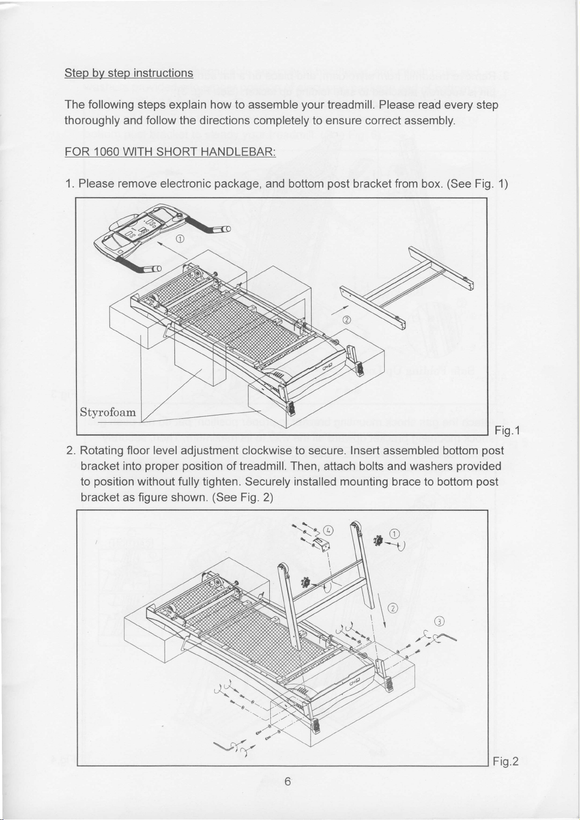
Step by step
instructions
The following steps explain how to assemble
thoroughly
FOR 1060 WITH
1. Please remove
follow the directions
and
SHORT
electronic
HANDLEBAR:
completely to ensure correct assembly.
package,
and bottom
your
treadmill.
post
Please read
bracket from box.
every step
(See
Fig. 1)
2. Rotating floor level adjustment clockwise to secure. Insert assembled
proper position
bracket
to
bracket as
into
position
without fully tighten.
figure
shown.
(See
of treadmill. Then, attach bolts and washers
Securely
Fig. 2)
installed mounting
brace to bottom
bottom
o
*,*
Fig.1
post
provided
post
=4?
Fig.2
6
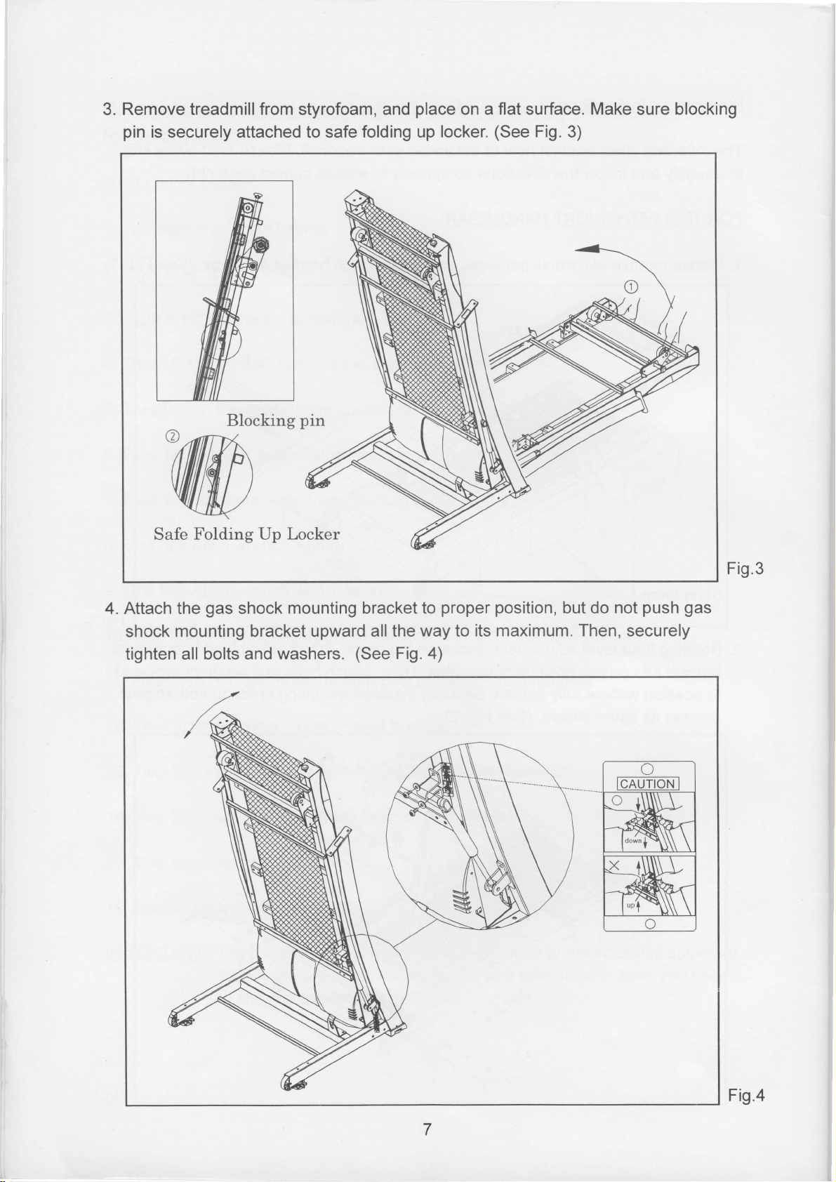
3. Remove treadmill
pin
is
securely
from
attached
styrofoam,
to safe
and
folding up
place
locker.
on a flat surface. Make
(See
Fig.
3)
sure
blocking
Safe Folding Up
4.Attach the
shock
mounting bracket upward
tighten all
Blocking
gas
shock mounting bracket to
bolts and washers.
pin
Locker
(See
proper position,
all the way to
Fig.
)
but do not
its maximum. Then,
securely
Fig.3
push gas
Fig.4
 Loading...