

SportsArt E875 User Manual [nl]

E875 OWNER’S MANUAL CONTENTS
1. INTRODUCTION .............................................................................. 2
2. SAFETY PRECAUTIONS ................................................................ 3
3. LIST OF PARTS ............................................................................... 7
4. ASSEMBLE THE PRODUCT .......................................................... 9
STEP 1 Secure the Pedestal................................................................ 9
STEP 2 Install the Moving Parts .......................................................... 11
STEP 3 Install the Supports ................................................................ 12
STEP 4 Install the Stationary Handlebars .......................................... 13
STEP 5 Install the Stoppers and Covers ............................................. 14
STEP 6 Install the Footplates .............................................................. 15
STEP 7 Move the Product into Place .................................................. 16
STEP 8 Level the Product .................................................................. 17
STEP 9 Ground Wire Installations ...................................................... 18
STEP 10 Beware of Moving Parts ........................................................ 19
5. UNDERSTAND THE E875 DISPLAY .............................................. 20
DISPLAY Overview .............................................................................. 20
DISPLAY Specications ....................................................................... 21
DISPLAY Windows ............................................................................... 21
DISPLAY Keys ...................................................................................... 21
6. OPERATE THE PRODUCT ............................................................. 23
OPERATION Quick Start ..................................................................... 23
OPERATION Start a Workout Program ............................................... 23
OPERATION Display ........................................................................... 24
OPERATION Cool Down ..................................................................... 25
OPERATION Workout Programs ......................................................... 25
OPERATION User Preferences and Component Versions................... 28
7. ABOUT HEART RATE DETECTION ................................................ 29
HEART RATE Telemetry ...................................................................... 29
HEART RATE Contact ......................................................................... 29
8. GUIDELINES FOR EXERCISE ....................................................... 30
9. ACCESSORIES ............................................................................... 31
ACCESSORIES Entertainment Cap .................................................... 32
10. MAINTENANCE ............................................................................. 33
MAINTENANCE Messages .................................................................. 33
MAINTENANCE Lubrication ................................................................ 33
MAINTENANCE Lubrication Procedure............................................... 34
MAINTENANCE Cleaning the Glide Rails ........................................... 35
MAINTENANCE Schedule ................................................................... 36
MAINTENANCE Task List (Elliptical Trainers) ..................................... 37
MAINTENANCE One-Year Maintenance Log ...................................... 38
MAINTENANCE Electronics Block Diagram ........................................ 39
1. INTRODUCTION
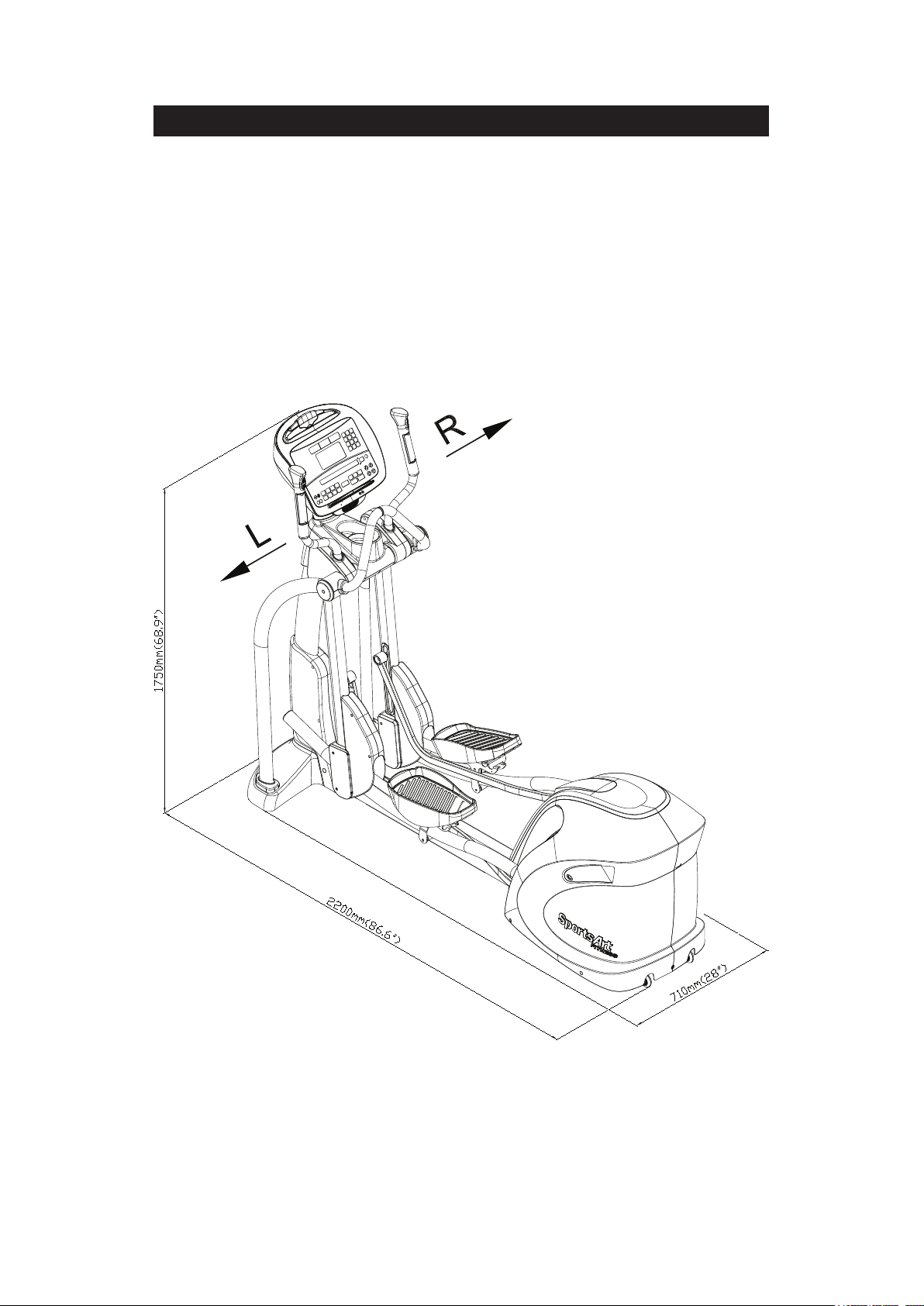
Congratulations on your purchase of one of the nest exercise products on the
market today, the SportsArt E875 Elliptical trainer. Constructed of high quality
materials and designed for years of reliable usage, this product was made to
become an integral part of your commercial tness venue.
Before this product is assembled or operated, we recommend that you familiarize
yourself with this manual. Understanding the correct assembly and operation of
this product will help ensure that exercisers obtain their tness goals safely and
successfully.
2

2. SAFETY PRECAUTIONS
Your SportsArt elliptical trainer was designed and built for optimum safety. However
certain precautions apply whenever you use your elliptical trainer.
Please read the entire manual before assembly and operation. Also, please note the
following safety precautions:
● Please read the instructions carefully and install the elliptical trainer as instructed.
● Assemble and operate the elliptical trainer on a solid, level surface. DO NOT use
outdoors or near water.
● Never allow children on or near the elliptical trainer.
● Check the elliptical trainer before every use. Make sure all parts are assembled,
and all fasteners are tightened. DO NOT use the elliptical trainer if the unit is
disassembled in any way.
● Keep your hands away from moving parts.
● Wear proper workout clothing; DO NOT wear loose clothing. DO NOT wear
shoes with leather soles or high heels. Tie all long hair back. DO NOT go barefoot
on this product.
● Be careful when mounting and dismounting the unit.
● The elliptical trainer may or may not stop immediately if an object becomes caught
or impedes normal motion.
● DO NOT use any accessories that are not specically recommended by the
manufacturer. Such parts might cause injuries or cause the unit to fail.
● Close supervision is necessary when this elliptical trainer is used by, on, or near
children, invalids, or disabled persons.
● Use this elliptical trainer only for its intended use as described in this manual.
● Never operate this elliptical trainer if it has been damaged in any way. If it is not
working properly, or has been dropped or damaged, contact your dealer.
● Keep all air ventilation areas free of blockage.
● Never drop or insert any object into any opening.
● DO NOT operate where aerosol (spray) products are being used or where oxygen
is being administered.
● The general user weight limit for this elliptical trainer is 227kg (500lb). Note that
at resistance level 40 this product meets standards for users of up to 150kg (330lb).
● This elliptical trainer is not intended for use by persons (including children)
with reduced physical, sensory or mental capabilities, or lack of experience
and knowledge, unless they have been given supervision or instruction
concerning use of this bike by a person responsible for their safety.
● Children should be supervised to ensure that they do not play with the
elliptical trainer.
3

2. SAFETY PRECAUTIONS (CONTINUED)
Caution
If you feel any pain or abnormal sensation, STOP YOUR WORKOUT and
consult your physician immediately. Work within your recommended exercise level. DO NOT work to exhaustion.
Before beginning any exercise program, you should consult with your doctor. It is recommended that you undergo a complete physical examination.
Note: This equipment has been tested and found to comply with the limits
for a Class B digital device, pursuant to part 15 of the FCC Rules. These
limits are designed to provide reasonable protection against harmful interference in a residential installation. This equipment generates, uses,
and can radiate radio frequency energy and, if not installed and used in
accordance with the instructions, may cause harmful interference to radio
communications. However, there is no guarantee that interference will not
occur in a particular installation. If the user desires to correct such interfer-
ence, it is at the user’s own expense.
Warning
Heart rate monitoring systems may be inaccurate. Over exercise may
result in serious injury or death. If you feel faint, stop exercise immediately
and consult a medical physician.
4

2. CONSIGNES DE SÉCURITÉ
5

2. CONSIGNES DE SÉCURITÉ (SUITE)
6
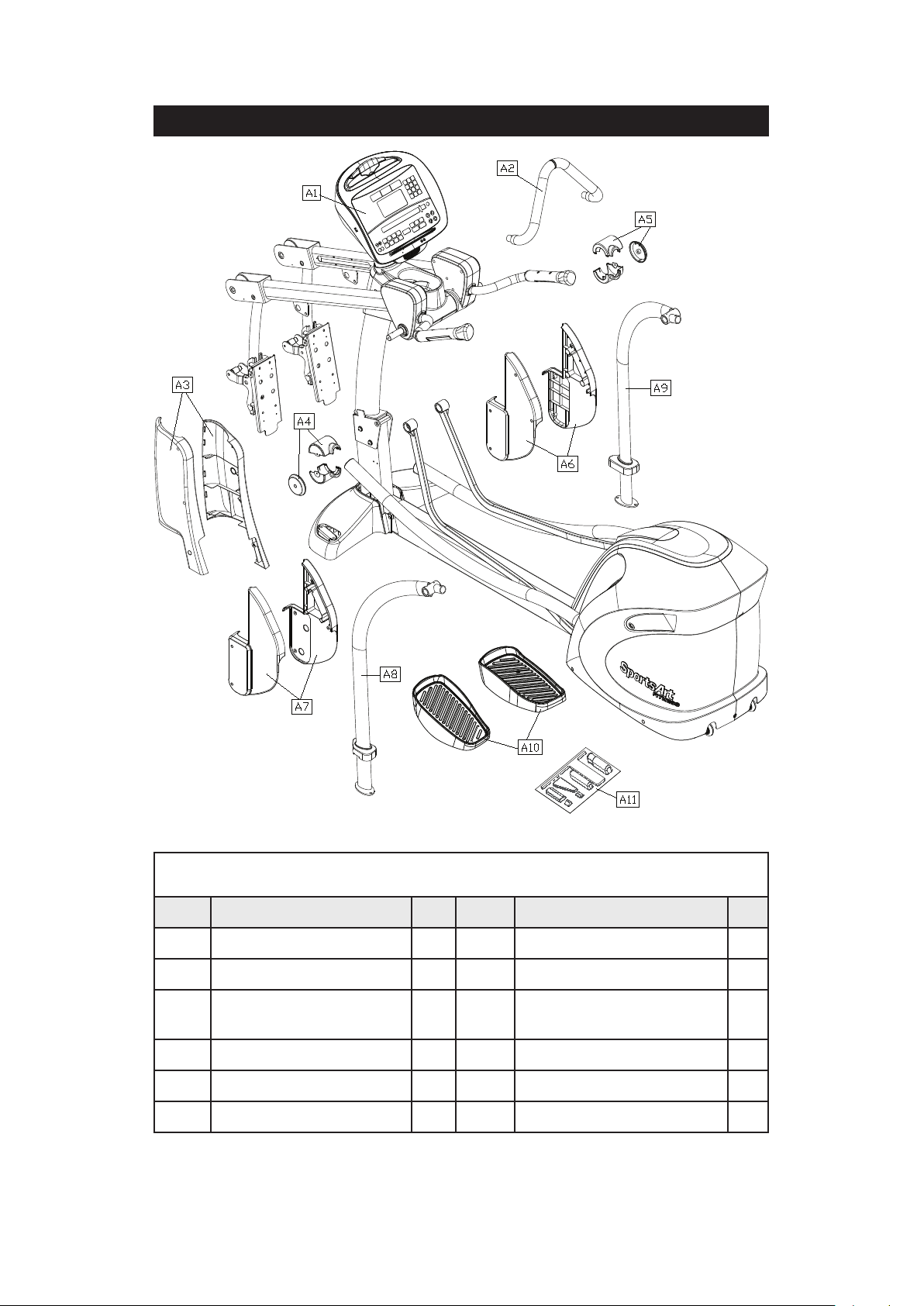
3. LIST OF PARTS
Assembly Parts
No. Name Qty. No. Name Qty.
A1 Main frame 1 A7 Left roller cover 1
A2 Stationary handlebar 1 A8 Support tube, left 1
A3
A4 Joint cover, left 1 A10 Foot pedals 1
A5 Joint cover, right 1 A11 Hardware kit 1
A6 Rear roller cover 1
Pedestal covers, left
and right
1 A9 Support tube, right 1
7

Components in the Hardware Kit
No. Name Qty. Specication Notes
Mushroom top inner hex screw 6 M10*P1.5*L25
10
11 Stride adjustment linkage cover 2
12 Hex nut 2 M10*P1.5
13 Round head phillips screw 4 M4*L12
14
Spring washer 6 M10
Washer 6 D21*d10.5*t1.5
Stopper 2 30-30
Secondary roller bolt 2 D9.96*L67
Self-lubricating bushing 4
Secondary roller 2 D58*t23
L-shaped Allen wrench 1 M4
L-shaped Allen wrench 1 M5
L-shaped Allen wrench 1 M6
Double open-end wrench 1 (8*17)
Double open-end wrench 1 (14*15)
Screwdriver handle 1 Green
Screwdriver bit 1 Flat and Phillips
Components on the Product
No. Name Specication Notes
21 Round head Phillips screw M4*P0.7*L8
22
23
24
25
26 Round head phillips screw M5*P0.8*L15
27 Mushroom top Phillips screw M5*P0.8*L12
28 Inner hex screw M5*L16
Inner hex screw 5/16”*L2-1/4” half
Flat washer D20*d8*t2.0
Inner hex screw M6*L15
Handlebar washer D20*d7*t2.0
Mushroom top inner hex screw M8*L15
Spring washer M8
Inner hex screw M6*L15
Handlebar washer D20*d7*t2.0
8
4. ASSEMBLE THE PRODUCT
Follow instructions below to assemble this product. Note that in this manual
the words “left” and “right” are used to refer to the product and its parts. As
such, these designations correspond to the “left” and “right” sides of a person
in position to exercise on this product. Also, for brevity, the word “screws” is
used where screws, washers, and other hardware may be involved.
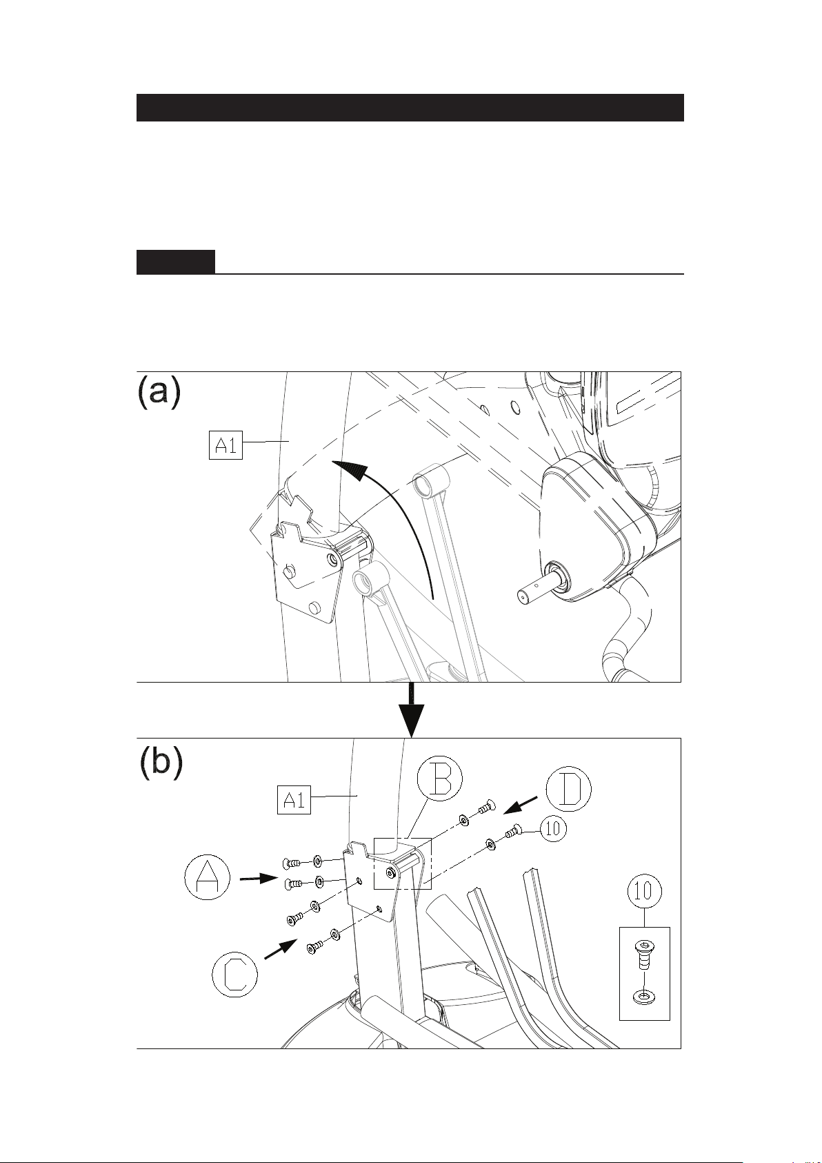
STEP 1 Secure the Pedestal
Please follow instructions (a) through (b) to secure the pedestal.
(a) Lift the pedestal (A1).
(b) Secure screws (10) in sequence. Secure screws in area A, followed by
those in area B. Then secure screws in area C, followed by those in area D.
9
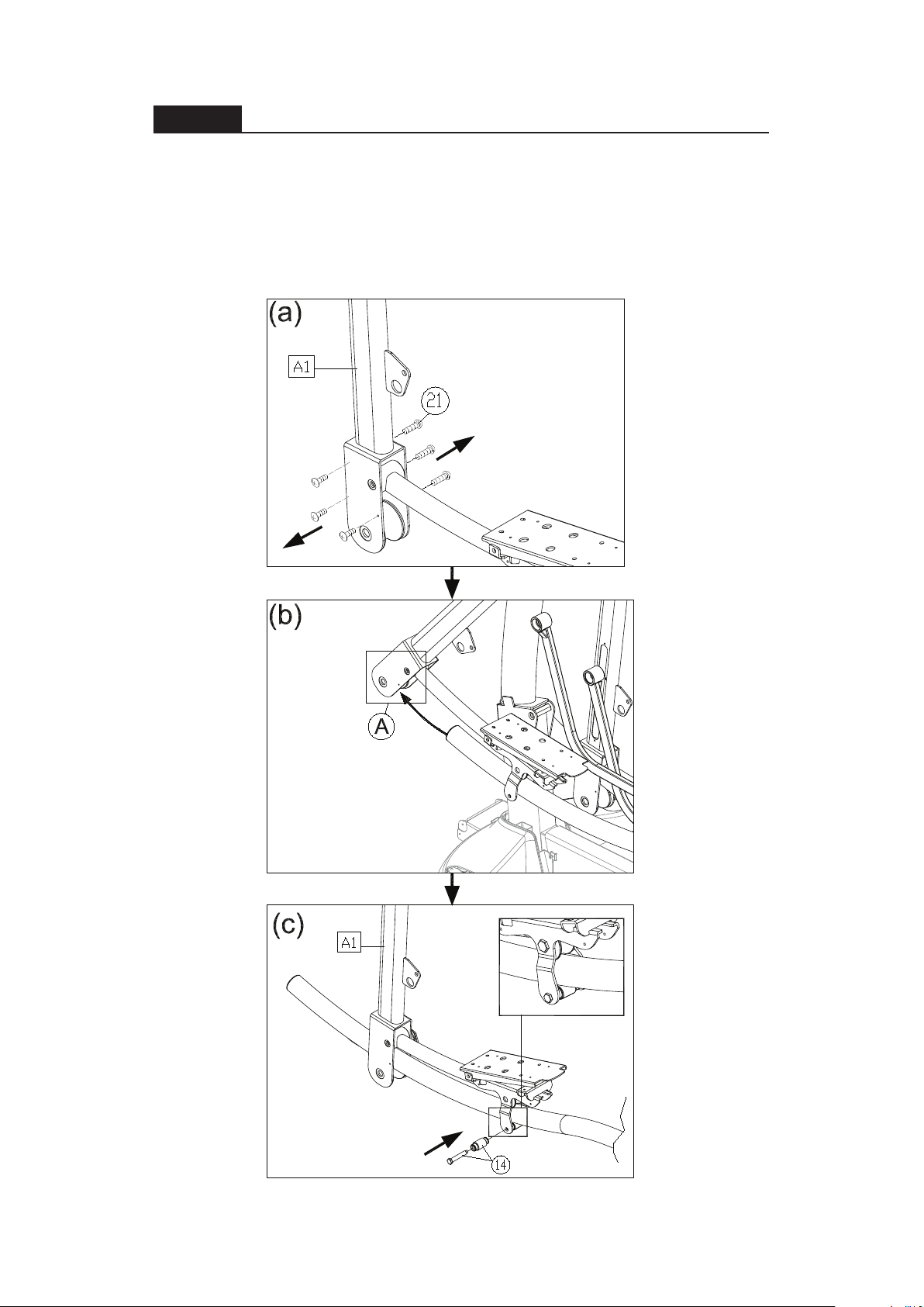
STEP 2 Install the Moving Parts
Follow instructions (a) through (e) to install the moving parts.
(a) Remove screws (21) from the stride arm attached to the main frame (A1).
(b) Once slip the glide rail into (Part A), then place the pedal carriage lightly
on the glide rail support.
(c) Connect the guide roller (14) on the bottom of the glide rail. (Please note
the direction to insert the screw is from outside to inside.).
10
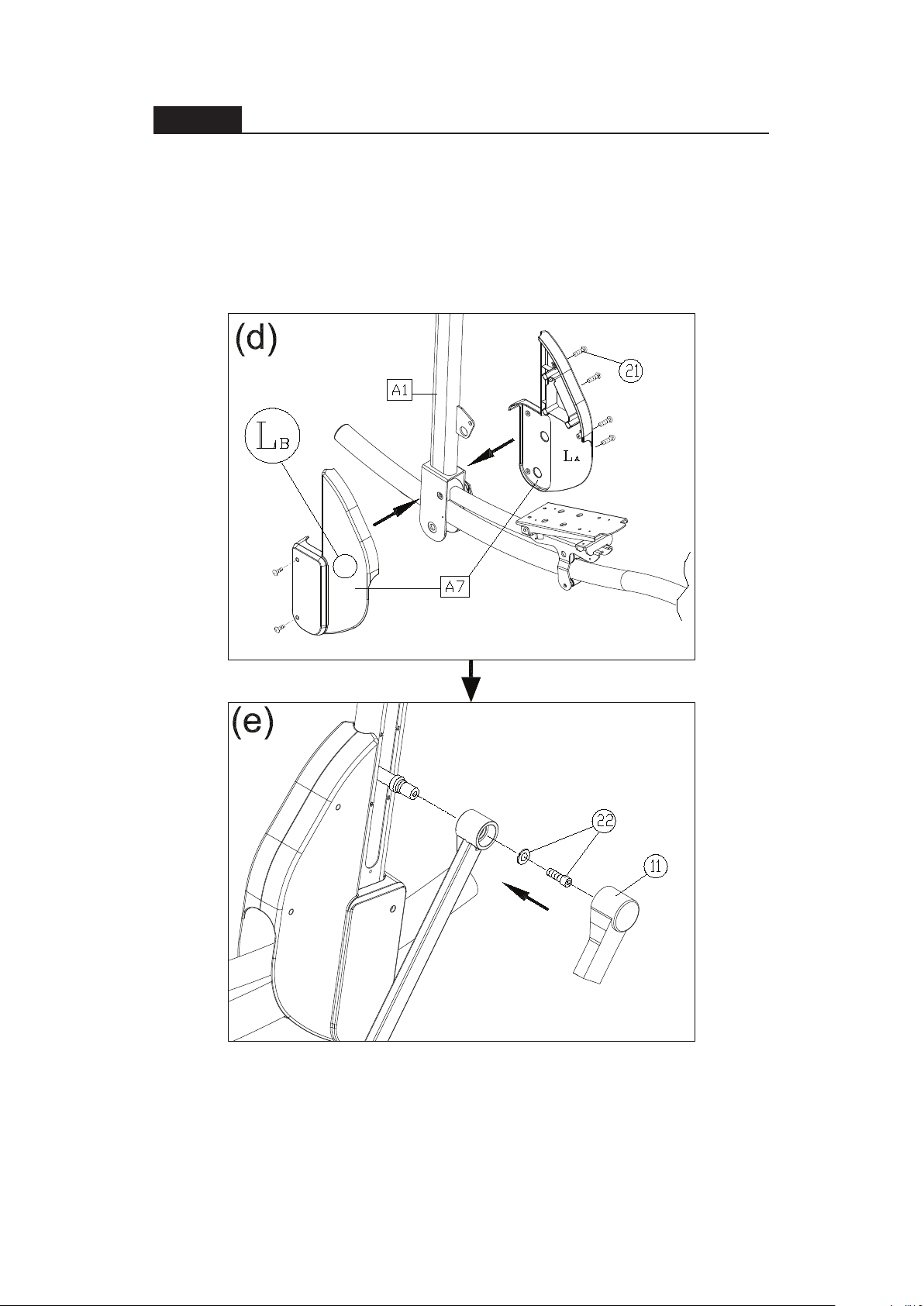
STEP 2 Install the Moving Parts (Continued)
(d) Separate the roller covers (A7). Snap them together into place on the
product. The secure them with screws (21).
(e) On the left side of the product, remove the screw (22) from the stride
adjustment linkage. Place the stride adjustment linkage into place on the
bushing, and use the screw (22) to secure it into place. Then press the stride
adjustment linkage cover (11) into place. Carry out the same procedure on
the right side of the product as well.
Warning: Consult the manual and follow all assembly
instructions carefully. Please note that incorrect assembly
may present a danger to the exercise, will damage the
elliptical and void the warranty.
11
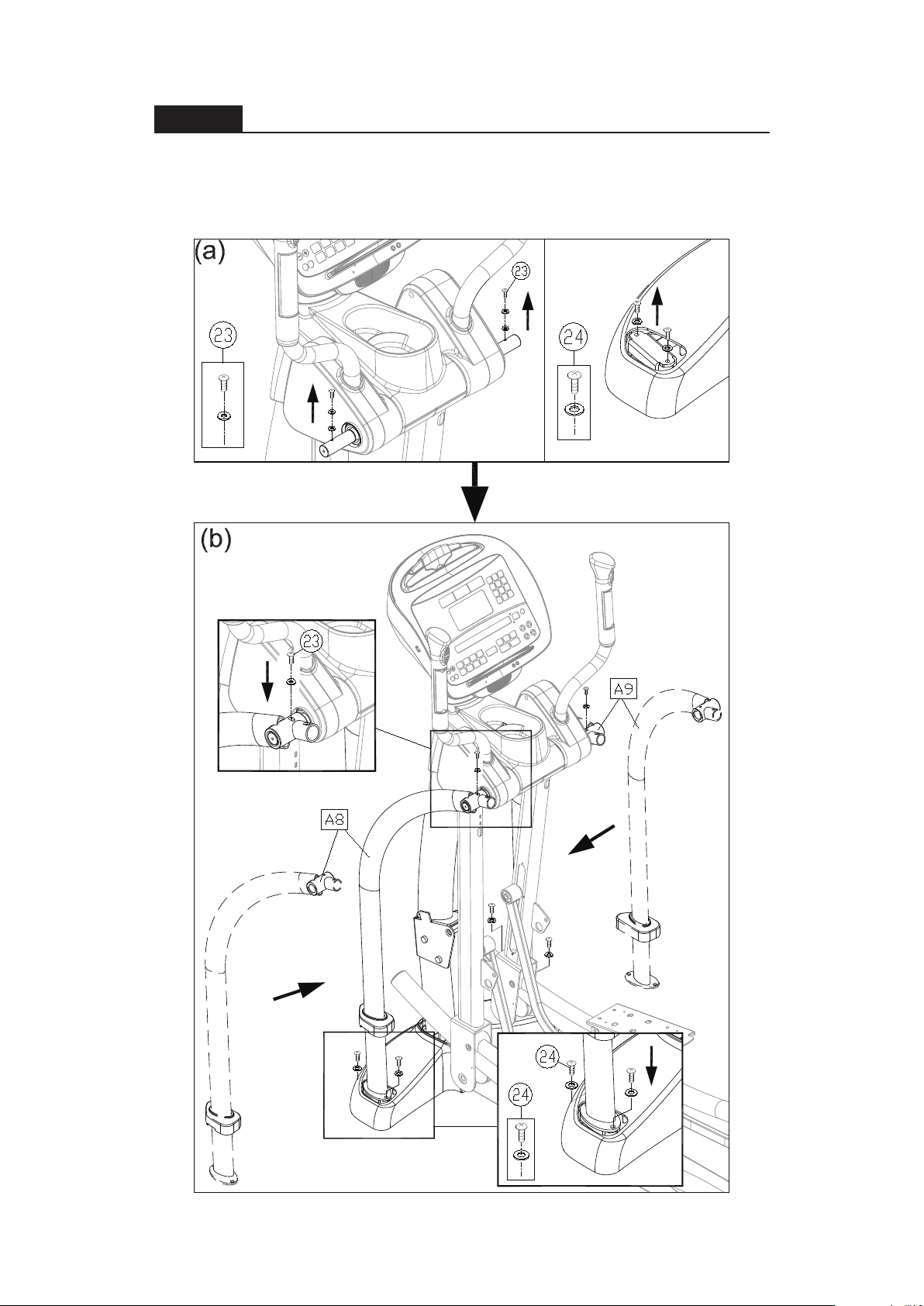
STEP 3 Install the Supports
Follow steps (a) through (c) to secure the support tubes.
(a) Remove support tube screws (23)(24) from the main frame (A1).
(b) Insert left and right support tubes (A8,A9) onto the axle area and base,
and loosely secure them into place with screws (23,24).
12
 Loading...