

SportsArt E850 User Manual [nl]

E850 OWNER’S MANUAL CONTENTS
1. INTRODUCTION .............................................................................. 2
2. SAFETY PRECAUTIONS ................................................................ 3
3. LIST OF PARTS ............................................................................... 5
4. ASSEMBLE THE PRODUCT ........................................................... 7
STEP 1 Unbox the Unit ........................................................................ 7
STEP 2 Assemble the Pedestal............................................................ 8
STEP 3 Install the Upper Cover............................................................ 9
STEP 4 Install Stride Linkages and Footplate Carriages. .................... 9
STEP 5 Install Left/Right Supports ....................................................... 10
STEP 6 Secure the Rail Base Cover ................................................... 11
STEP 7 Move the Unit into Place ......................................................... 12
STEP 8 Level the Unit .......................................................................... 13
STEP 9 Ground Wire Connection ........................................................ 14
STEP 10 Avoid Safety Hazards ............................................................ 14
5. MECHANICAL ADJUSTMENTS ...................................................... 15
6. UNDERSTAND THE E850 DISPLAY ............................................... 16
DISPLAY Overview .............................................................................. 16
DISPLAY Windows ............................................................................... 17
DISPLAY Keys ..................................................................................... 17
DISPLAY Specications ....................................................................... 18
7. OPERATE THE E850 ELLIPTICAL TRAINER ................................. 18
OPERATION QUICK START Mode ..................................................... 18
OPERATION START Mode .................................................................. 19
OPERATION Cool Down ...................................................................... 21
OPERATION Workout Programs ......................................................... 21
OPERATION User Preferences and Product Information .................... 23
8. ABOUT HEART RATE DETECTION ................................................ 25
HEART RATE Telemetry ...................................................................... 25
HEART RATE Contact ......................................................................... 25
9. GUIDELINES FOR EXERCISE ........................................................ 26
10. MAINTENANCE ............................................................................. 27
MAINTENANCE Lubricate the Shoulder Area ..................................... 27
MAINTENANCE Clean the Glide Rail .................................................. 28
MAINTENANCE Schedule ................................................................... 29
MAINTENANCE Task List (Elliptical Trainers) ..................................... 30
MAINTENANCE One-Year Maintenance Log ...................................... 31
MAINTENANCE Electronics Block Diagram ........................................ 32
11. SAFETY PRECAUTIONS IN FRENCH .......................................... 33
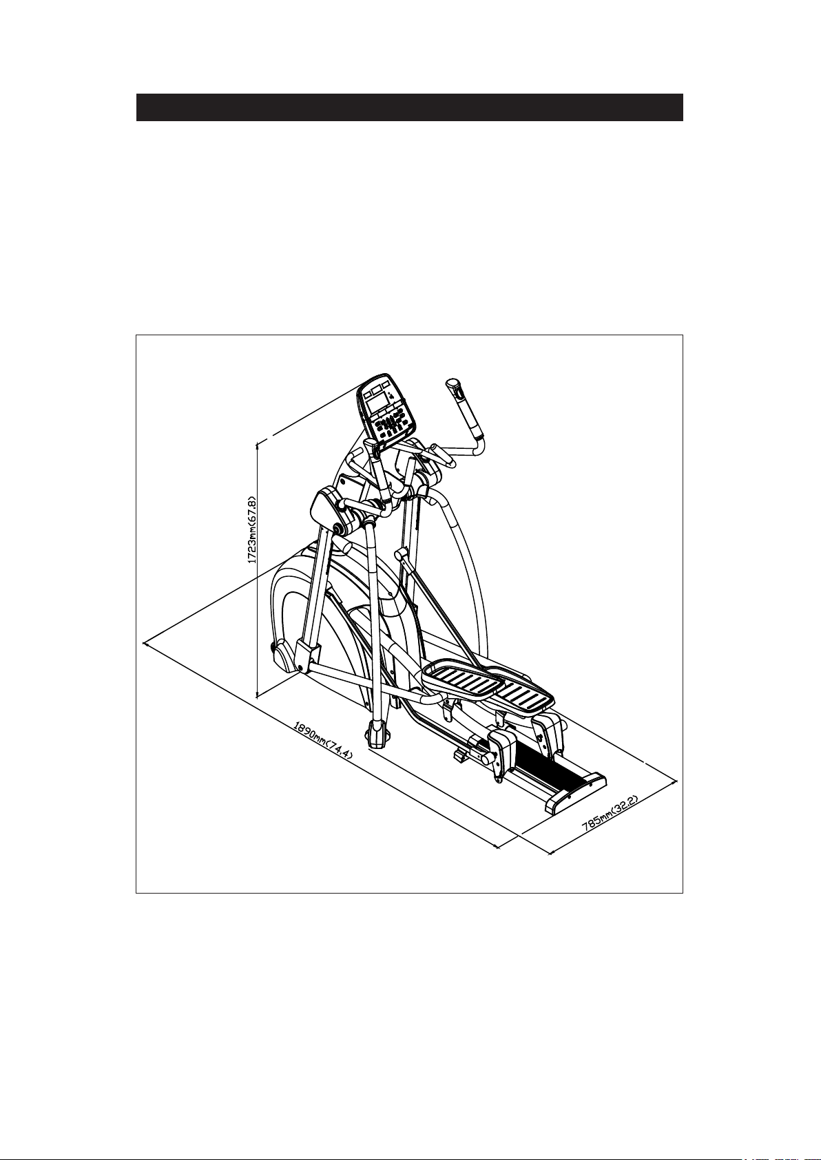
1. INTRODUCTION
Congratulations on your purchase of one of the nest exercise products on the market
today, the SportsArt E850 elliptical trainer. Constructed of high quality mat erials and
designed for y e ars o f r el ia b le u sa ge, this product was mad e t o become a n integral
part of your commercial tness venue.
Before this product is assembled or operated, we recommend that you familiarize yourself with this manual. Understanding the correct methods of assembly
and operation will help ensure that exercisers obtain their tness goals safely and
successfully.
2

2. SAFETY PRECAUTIONS
This product was designed and built for optimum safety. H owever certain precautions apply during the use of this product. Please note the following safety
precautions:
• Please read the entire manual before assembly and operation. Make
sure the product is installed and operated as instructed in this manual.
• Assemble and operate the product on a solid, level surface. Do not use
outdoors or near water, including pools and saunas.
• Check the product before every use. Make sure all parts are assembled, and all fasteners are tightened. Do not use the product if it is disassembled in any way.
• Wear proper workout clothing. Do not wear loose clothing. Do not wear
shoes with leather soles or high heels. Tie all long hair back. Do not go
barefoot on this product.
• Keep away from moving parts. Moving parts may or may not stop immediately if an object becomes caught or impedes normal motion.
• Use this product only for its intended purpose as described in this
manual.
• Be careful when mounting and dismounting the unit.
• Never operate this product if it has been damaged in any way. If it is
not working properly, or has been dropped or damaged, contact a service
technician for repairs.
• Do not use accessories that are not specically recommended by the
manufacturer. Such parts might cause injuries or cause the unit to fail.
• Keep all air ventilation areas free of blockage. Never drop or insert any
object into any opening.
• Do not operate where aerosol (spray) products are being used or where
oxygen is being administered.
• This product is not intended for use by persons (including children) with
reduced physical, sensory, or mental capabilities, or by people who are
otherwise decient in product knowlege or experience. If such people use
this product, they should be given training and be supervised at all times
by someone responsible for their safety.
• Children should be supervised to ensure that they do not play on or
near the product.
• The user weight limit for this product is 180 kg, 400 lb. At maximum
resistance, level 20, this product meets standards for users up to 150 kg,
330 lb.
CAUTION: If you feel any pain or abnormal sensations, STOP YOUR
WORKOUT and consult your physician immediately. Work within your
recommended exercise level. DO NOT work to exhaustion. Before beginning
any e x er cise prog ram , y ou sh ould cons ul t with y o ur doct or. It is recommended that
you undergo a complete physical examination.
WARNING! Heart rate mo nitoring syste m s m ay be inaccurate. Too much exercise
may resu lt in serious i njury or death . If you f eel fain t, stop e x ercising i mmedia tely.
3

2. SAFETY PRECAUTIONS (CONTINUED)
Note : This equipment ha s been tested and f ound to comply with the lim its for a Class
B digital de vice, p ursua nt to p art 15 o f the F CC R ules . These l imits ar e desig ned to
provide reasonable protect ion against harmful inter ference in a residential instal lation. Thi s equipment ge nerates, us es and can radiate r adio frequency e nergy and,
if not installed and use d in accordance with the instructio ns, may cause harmful
interference to radio communications. However, there is no guarantee that interference will not occur in a particular installation. If the user desires to correct the
interference, i t is at the us er’s o wn expe nse.
WARNING! Only qualied technicians should be allowed to contact electrical
components such as circuit boards. Some components carry an electrical charge
even after use has been discontinued or the product has been unplugged. For
products with power cords, turn off unit power, wait ve minutes, then disconnect
the power cord from the po wer socke t. For products witho ut power cords, le t the unit
sit without use for ve minutes. Only after taking such precautions should covers be
removed and electrical components be accessed.
4
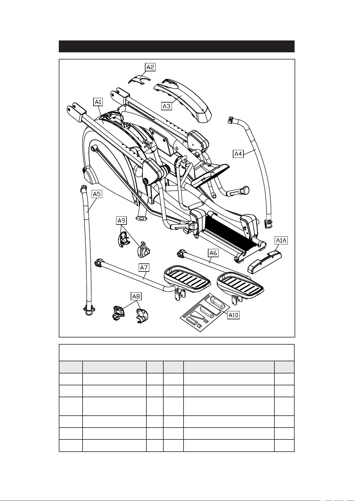
3. LIST OF PARTS
Assembly Parts
No. Name Qty. No. Name Qty.
A1 Main body 1 A6 Left footplate assembly 1
A1A Rail base cover 1 A7 Right footplate assembly 1
A2 Small cover 1 A8
A3 Upper cover 1 A9 Base covers for left support 1
A4 Right support 1 A10 Hardware kit 1
A5 Left support 1
Base covers for right
support
5
1

Components in the Hardware Kit
No. Name Qty. Specication Notes
33 Mushroom top Phillips screw 6 M4*L16
34 Phillips screw 4 M5*P0.8*L10
35 Left/right adjustment rod cover 2
36 Screw insert 4
37 M10 nut cap 2
38 Screw cap 2
L-shaped Allen wrench 1 M6
L-shaped Allen wrench 2 M4
Double open-end wrench 1 8*17
Double open-end wrench 1 13*19
T-shaped Allen wrench 1 M5
Screwdriver shank 1 at and Phillips
Screwdriver handle 1 green
Components on the Product
No. Name Specication Notes
Inner hex screw M8*L20
41
42 Mushroom top Phillips screw M4*L16
43
44
45
46
Spring washer M8
Serrated washer D18*d8.5*t2.0*19T
Inner hex screw M8*L25
Spring washer M8
Washer D17*d8.3*t1.0
Inner hex screw M6*L15
Serrated washer D20*d6.2*t2.0*19T
Inner hex screw 5/16”*L2-1/4 inch
Seat roller washer D17*d8*t2.0
Roller axle
Flat washer D21*d10.5*t2
Lock nut M10
47
PU sheath D12*D8*L45
Axle M5*L71
Flat washer D17*d8.3*t1
Mushroom top inner hex screw M5*6
6
4. ASSEMBLE THE PRODUCT
Follow instructions below to assemble this product. Note that in this manual
the words “left” and “right” are used to refer to the product and its par ts. As
such, these des ignations correspond to th e “left” and “right” sides of a person
in position to exercise on this product. Also, for brevity, the word “screws” is
used where screws, washers, and other hardware may be involved.
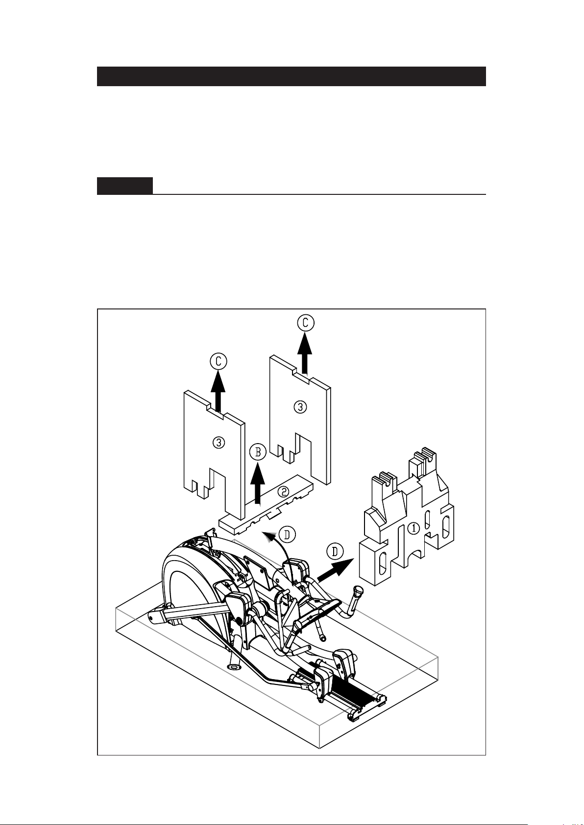
STEP 1 Unbox the Unit
Please follow instructions A through D to remove packaging material and to
place the unit on top of the flattened cardboard.
A. Remove the box top and the plastic sheet.
B. Start working from above, first removing Styrofoam (2) above the unit.
C. Lift Styrofoam (3) on both sides of the unit upward to remove it. Place
parts aside separately.
D. Lift the pedestal to remove the Styrofoam (1) in the middle.
7
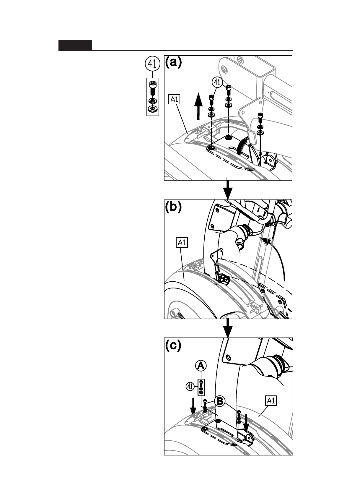
STEP 2 Assemble the Pedestal
Please follow instructions
(a) through (b ) to a ssemb le
the pedestal.
(a) First, remove screws
(41) from the pedestal
mount on the main body
(A1).
(b ) P ush the pedestal up to
the vertical position while
preventing the data cable
from getting pinched.
(c) Secure screws (41) , first
in area (A), then in area
(B).
8
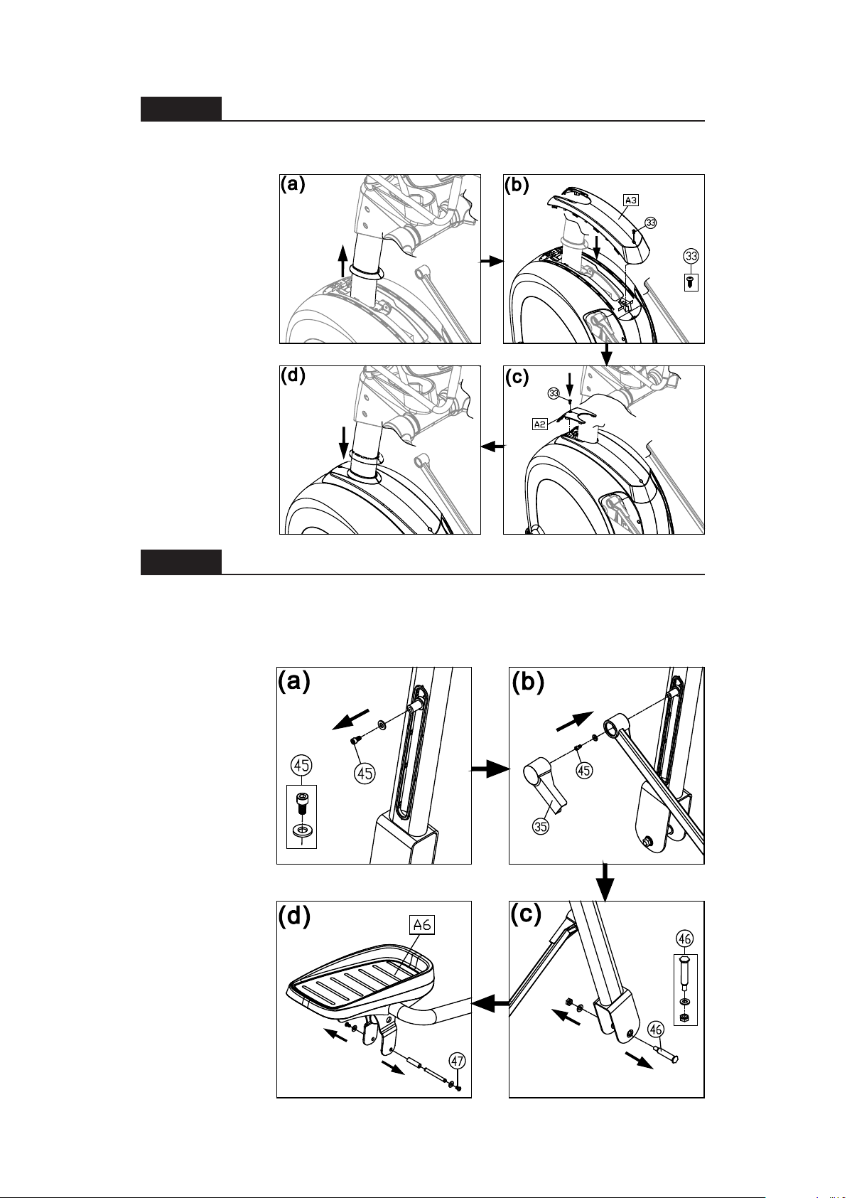
STEP 3 Install the Upper Cover
Please follow instructions (a) through (d) to install the upper cover.
(a) Slide the water guard up the pedestal. (This ring must be placed above
the upper cover.)
(b) Install the
upper cover and
secure it with
screw (33).
(c) Install the
small cover (A2)
and secure it with
screw (33).
(d ) Slide the wate r
guard down the
pedestal until it
fits snugly again st
the covers.
STEP 4 Install Stride Linkages and Footplate Carriages
Please follow steps (a) through (f) to install stride linkages and footplate
carriages on both sides of the product.
(a) Remove bolts ( 45 ) from the bu shing on the stride adju stment m echanism .
(b ) Align the hole in the stride link age with the bushing on the stride a djustment
mechanism, and
press the stride
linkage into place
on the bushing.
Secure the stride
linkage with bolts
(45). Then insert
the stride linkage
cover (35) into
place. Follow the
same procedure
on both sides.
(c) Remove bolts
(46) from the
vertical arms on
both sides.
(d) Remove
screws (47) from
the left footplate
carriage (A6).
9
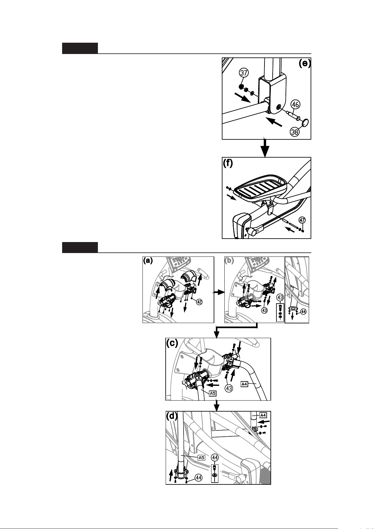
STEP 4 Install Linkages/Carriages (Continued)
(e) Insert the front of the footplate carriage into
the vertical arm. Align it with the hole and use
bolt ( 46 ) to secure i t int o place. Th en insert caps
(37, 38) into place.
(f). Lubricate the area where the rod contacts
the bushing, hold the footplate carriage into
place, and secure it with screw (47). Perform
the same actions on both sides of the product.
STEP 5 Install Left/Right Supports
Please follow
instructions (a) through
(f) to install left and
right supports.
(a) Remove screws a nd
remove covers from the
top of the left and right
supports.
(b ) Remov e screws (43 )
(44) from both sides.
(c) Put left and right
supports (A4,A5) into
place and loosely
secure screws (43) at
the top. Do not fully
secure these screws
yet.
(d) First, secure screws
(44) at the base of the
supports (A4,A5). Then
go back to the top and
secure screws (43).
10

STEP 5 Install Left/Right Supports (Continued)
(e) Put support base covers (A8, A9)
into place on both supports (A4,A5),
and secure them with screws (34).
(f) Set upper covers into place on
both supports, and secure them with
screws (42).
STEP 6 Secure the Rail Base Cover
Please follow instructions (a ) through
(b) to install the rail base cover.
(a) First, insert screw inserts (36 ) int o
the rail base plate.
(b) Set the rail base cover (A1A) in
place and secure it with screws (33).
11
 Loading...