

SportsArt 6300, 6100 User Manual
6300/6310 Treadmill Electronics Repair Manual
Version 2; Date: 11-11-04

6300/6310 Treadmill Electronics Repair Manual
The 6300/6310 Treadmill Electronics Repair Manual
guide for technicians in the field. If you have questions or comments, please write to Bob Baumgartner
at bob@sportsartamerica.com
Version 1 Date: 05-01-03
Version 2 Date: 11-11-04 – Reformatted, corrected, updated for changes to the emergency stop
knob and thermal fuse.
.
is designed to be a quick, easy troubleshooting
00

6300/6310 Treadmill Electronics Repair Manual - Contents
Contents
6300 Introduction – 6300 Treadmill Features
6300 – INTRODUCTION.01 – 6300 Treadmill Specifications at a Glance
6300 – INTRODUCTION.02 – 6300 Treadm ill Control Area
6300 – INTRODUCTION.03 – 6300 Display Windows
6300 – INTRODUCTION.04 – 6300 Display Keys
6300 – INTRODUCTION.05 – 6300 Display Unit Feedback LEDs
6300 – INTRODUCTION.06 – Operating the 6300 Treadmill: Start Up
6300 – INTRODUCTION.07 – Operating the 6300 Treadmill: Manual Operation
6300 – INTRODUCTION.08 – Operating the 6300 Treadmill: Stop Functions
6310 Introduction – 6310 Treadmill Features
6310 – INTRODUCTION.01 – 6310 Treadmill Specifications at a Glance
6310 – INTRODUCTION.02 – 6310 Display Windows
6310 – INTRODUCTION.03 – 6310 Display Keys
6310 – INTRODUCTION.04 – 6310 Display Unit Feedback LED
6310 – INTRODUCTION.05 – Operating the 6310 Treadmill: Start Up
6310 – INTRODUCTION.06 – Operating the 6310 Treadmill: Manual Operation
6310 – INTRODUCTION.07 – Operating the 6310 Treadmill: Stop Functions
6310 – INTRODUCTION.08 – Operating the 6310 Treadmill: Programs
6310 – INTRODUCTION.09 – Operating the 6310 Treadmill: KPH/MPH, Distance/Time, Clear
CONTENTS.01

6300/6310 Treadmill Electronics Repair Manual - Contents
Contents (Continued)
6300/6310 Operation – Explains 6300/6310 Operation in General
OPERATION.01 – 6300/6310 Power/Signal Diagram
OPERATION.02 – 6300/6310 Power/Signal Flow Explanation
OPERATION.03 – 6300/6310 Motor Compartment Components
6300/6310 Display – Includes 6300/6310 Display Wiring, LEDs, Test Procedures
DISPLAY.01 – 6300/6310 Display Board Wire Connection Diagram
DISPLAY.02 – 6300/6310 Display Board Wire Connection Picture
DISPLAY.03 – 6300/6310 Display Board LEDs
DISPLAY.04 – 6300/6310 Display VCC Circuit Voltage Test
DISPLAY.05 – 6300/6310 Display VBB Circuit Voltage Test
DISPLAY.06 – 6300/6310 Display Board Main Program IC U5
DISPLAY.07 – 6310 Display Board – Front View
6300/6310 Drive Board – Includes 6300/6310 Drive Board Wiring, LEDs
DRIVE BOARD.01 – Drive Board Wire Connection Diagram
DRIVE BOARD.02 – 6300/6310 Drive Board Wire Connection Picture
DRIVE BOARD.03 – 6300/6310 Drive Board LEDs – Normally Lit
DRIVE BOARD.04 – 6300/6310 Drive Board LEDs – Normally Not Lit
DRIVE BOARD.05 – 6300/6310 Drive Board Picture
CONTENTS.02

6300/6310 Treadmill Electronics Repair Manual - Contents
Contents (Continued)
6300/6310 Drive Motor System Operation
MOTOR.01 – 6300/6310 Motor System Operation
MOTOR.02 – 6300/6310 Voltage to Motor – Test Configuration
MOTOR.03 – 6300/6310 Voltage to Motor – Test Procedure, Test Results
MOTOR.04 – 6300/6310 Motor Circuit and OHM Test Configuration, Procedure
MOTOR.05 – 6300/6310 Transformer Test Configuration
MOTOR.06 – 6300/6310 Transformer Test Procedure, Results
MOTOR.07 – 6300/6310 Inductor Test Configuration, Procedure
MOTOR.08 – 6300/6310 Optic Sensor Signal Test
MOTOR.09 – 6300/6310 Optic Sensor Signal Test Procedure, Results
6300/6310 Incline System Operation
INCLINE.01 – 6300/6310 Incline System Operation
INCLINE.02 – 6300/6310 Voltage to Incline Motor – Test Configuration
INCLINE.03 – 6300/6310 Voltage to Incline Test Procedure, Results
INCLINE.04 – 6300/6310 Incline VR Voltage –Test Configuration
INCLINE.05 – 6300/6310 Incline VR Voltage Test Procedure, Results
6300/6310 Incline Calibration
CALIBRATION.01 – 6300/6310 Incline Calibration Overview
CALIBRATION.02 – Mechanical Calibration
CALIBRATION.03 – Electronic Calibration
CALIBRATION.04 – Incline Calibration Testing
CONTENTS.03

6300/6310 Treadmill Electronics Repair Manual - Contents
Contents (Continued)
6300/6310 Heart Rate System
HR.01 – Heart Touch Rate (HTR) Operation
HR.02 – POLAR Heart Rate (HR) Operation
HR.03 – HTR Board LED Operation, LED Indicator Definitions
HR.04 – Possible Malfunctions, T roubleshooting
HR.05 – HTR Cable/Handlebar Test Procedure
6300/6310 Troubleshooting
ERR1.01 – ERR 1 – Motor Movement
ERR1.02 – Troubleshooting: ERR1 Motor Movement
ERR1.03 – ERR 1 – No Motor Movement
ERR1.04 – Troubleshooting: ERR1 Motor Movement
ERR3.01 – ERR 3
ERR3.02 – ERR 3 Troubleshooting
ERR7.01 – ERR7
ERR7.02 – ERR7 Troubleshooting
NO DISPLAY.01 – Display Does Not Light
NO DISPLAY.02 – Troubleshooting: Display Does Not Light
CONTENTS.04

6300/6310 Treadmill Electronics Repair Manual - Contents
Contents (Continued)
Testing Components Unique to 6300/6310 Treadmills
FILTER.01 – EMI Filter
FILTER.02 – EMI Filter Test
THERMAL FUSE.01 – Thermal Fuse Placement
THERMAL FUSE.02 – Thermal Fuse Operation
THERMAL FUSE.03 – Thermal Fuse Troubleshooting
EMERGENCY STOP.01 – Emergency Stop Signal Diagram, Emergency Stop Knob Operation
EMERGENCY STOP.02 – Emergency Stop Knob Troubleshooting, Emergency Stop Knob Test Configuration
EMERGENCY STOP.03 – Emergency Stop Revision
KEYS.01 – Key Operation, Key Test Configuration
KEYS.02 – Key Test Procedure
Reference
REF.01 – 6300/6310 Drive Board LED Reference Chart
REF.02 – 6300/6310 Display LED Reference Chart, 6300/6310 Fuse Reference Chart
REF.03 – VR Voltages for Various SportsArt Treadmill DC Incline Motors
CONTENTS.05

6300/6310 Treadmill Electronics Repair Manual – 6300 Introduction
6300 Introduction –
6300 – INTRODUCTION.01 – 6300 Model Treadmill Specifications at a Glance
6300 – INTRODUCTION.02 – 6300 Treadm ill Control Area
6300 – INTRODUCTION.03 – 6300 Display Windows
6300 – INTRODUCTION.04 – 6300 Display Keys
6300 – INTRODUCTION.05 – 6300 Display Unit Feedback LEDs
6300 – INTRODUCTION.06 – Operating the 6300 Treadmill: Start Up
6300 – INTRODUCTION.07 – Operating the 6300 Treadmill: Manual Operation
6300 – INTRODUCTION.08 – Operating the 6300 Treadmill: Stop Functions
6300 Treadmill Features
6300 INTRO.00
6300/6310 Treadmill Electronics Repair Manual – 6300 Introduction
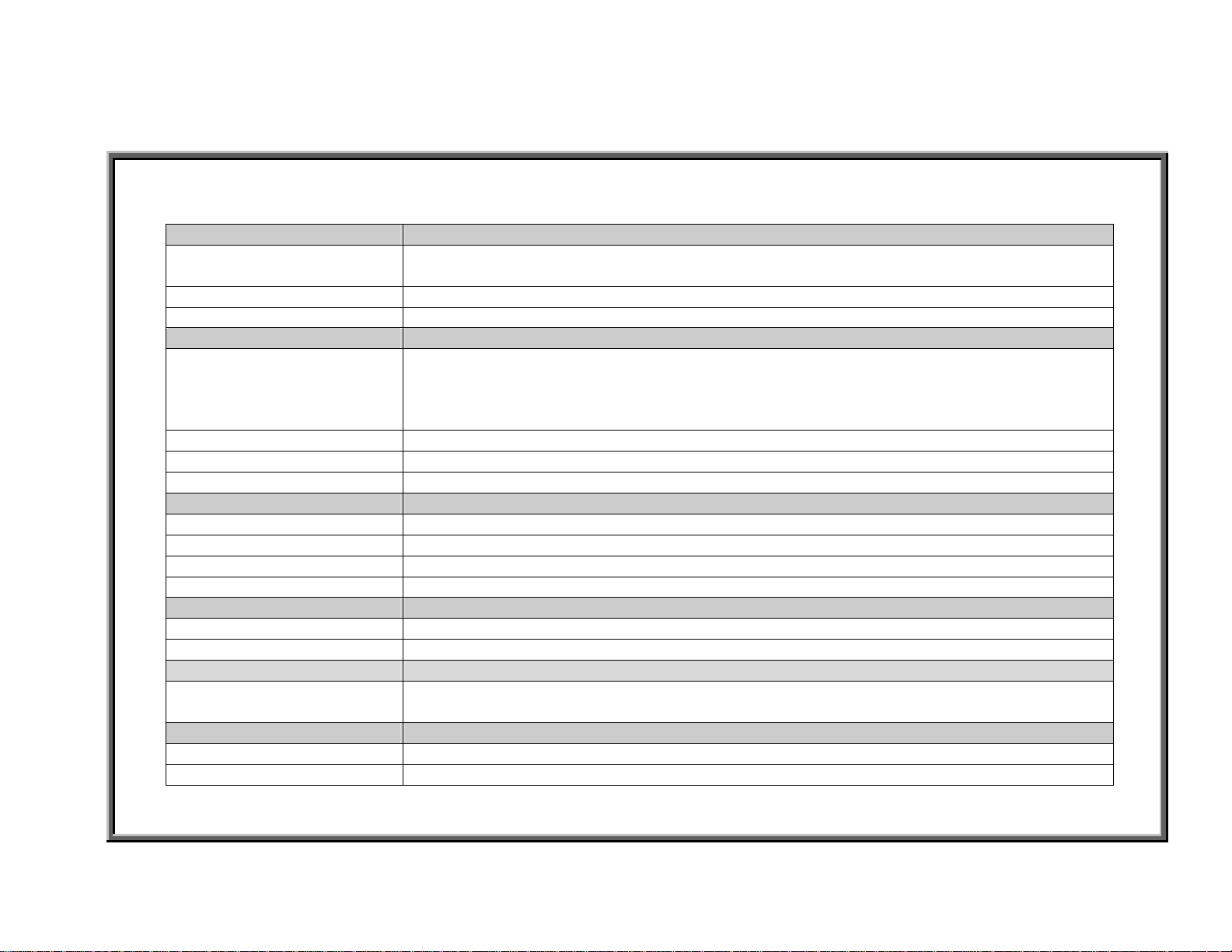
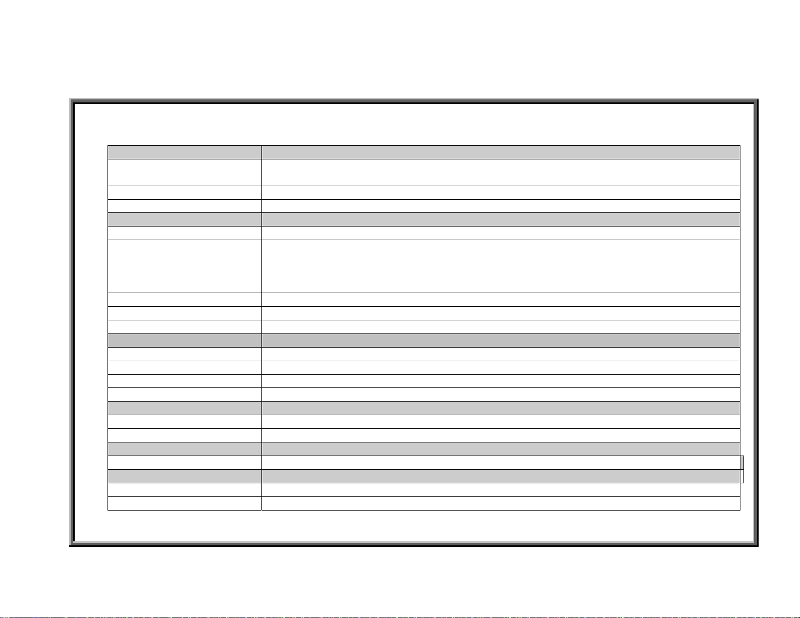
6300 Treadmill Specifications at a Glance
Function Description
Operation Modes Originally had only manual mode and no exercise programs. Exercise programs added July
2003. Program time added Jan. 2004
Heart Rate (HR) Function POLAR transmitter and heart touch rate (HTR) readings
Heart Rate Control (HRC) Heart rate target values: 65%; 72.5%; 80%, Sept. 2003
1.Distance / Incline (Board revised Feb. 2003 because incline stuck.)
Display – 7-Segment Digital
Display - Keypad PET touch type, Sept. 2003
Emergency St op Emergency stop knob on display (removed Sept. 2004); pause/ stop key on keypad
Drive Board Revised June 2004 (new is V3.2) after motor brush change
Motor Spee d 0.1-12.0 MPH (North America standard); 0.2-20.0 KPH (Europe)
Motor Highest Speed 2900 RPM
Motor Horse Power Originally 3.2 HP; revised to 4.0 Sept. 2003 with ribbed exterior
Motor Thermal Switch Turns on “Service” indicator if motor gets too hot, Sept. 2003
Incline Range 0-15%
Incline VR Calibration 0% position = 1.20 VDC; measured on VR blue and green wires
MPH in N. America
KPH in Europe
Power Requirements 120 VAC, 20 AMP dedicated
Frame Incline support added Nov. 2003; Color: Originally gray, became silver Nov. 2004
2.Calories / HR
3.Time / Pace
4.Speed / Mets (Display became C-Safe compatible Dec. 2004)
MPH determined by the IC chip. MPH =N. Americ an st a ndar d; KPH=Europea n standard.
Distance units cannot be changed by touching keys
6300 INTRO.01
6300/6310 Treadmill Electronics Repair Manual – 6300 Introduction
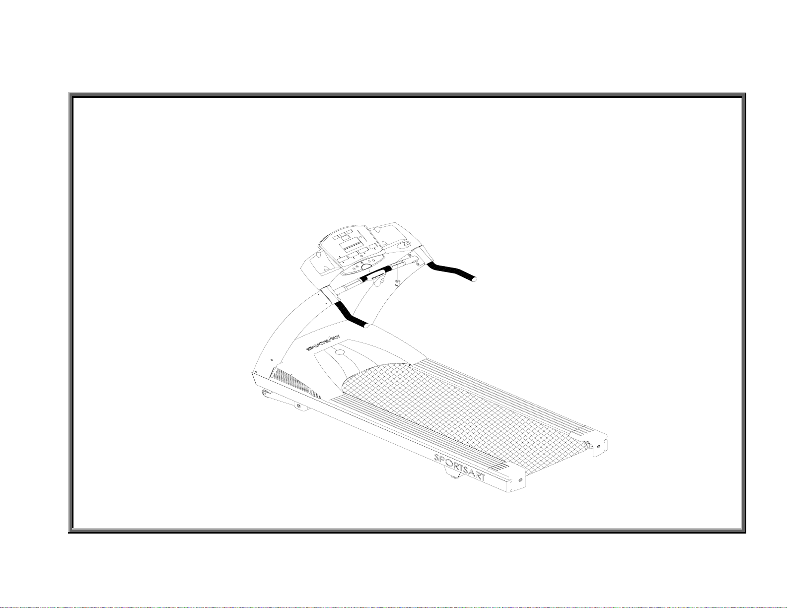
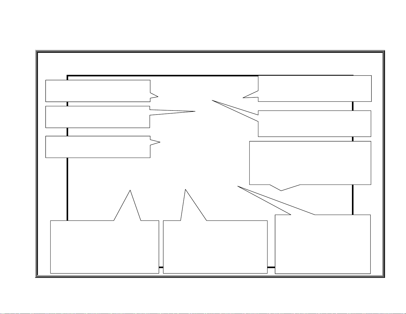
6300 Treadmill Control Area
Note: Picture
shows old type
HTR grips. As of
Sept. 2004,
HTR grips had
two, rather than
four, contact
plates.
Display
Emergency Stop Knob
(prior to Sept. 2004)
Keypad
HTR Grip (left)
HTR Grip (right)
6300 INTRO.02
6300/6310 Treadmill Electronics Repair Manual – 6300 Introduction
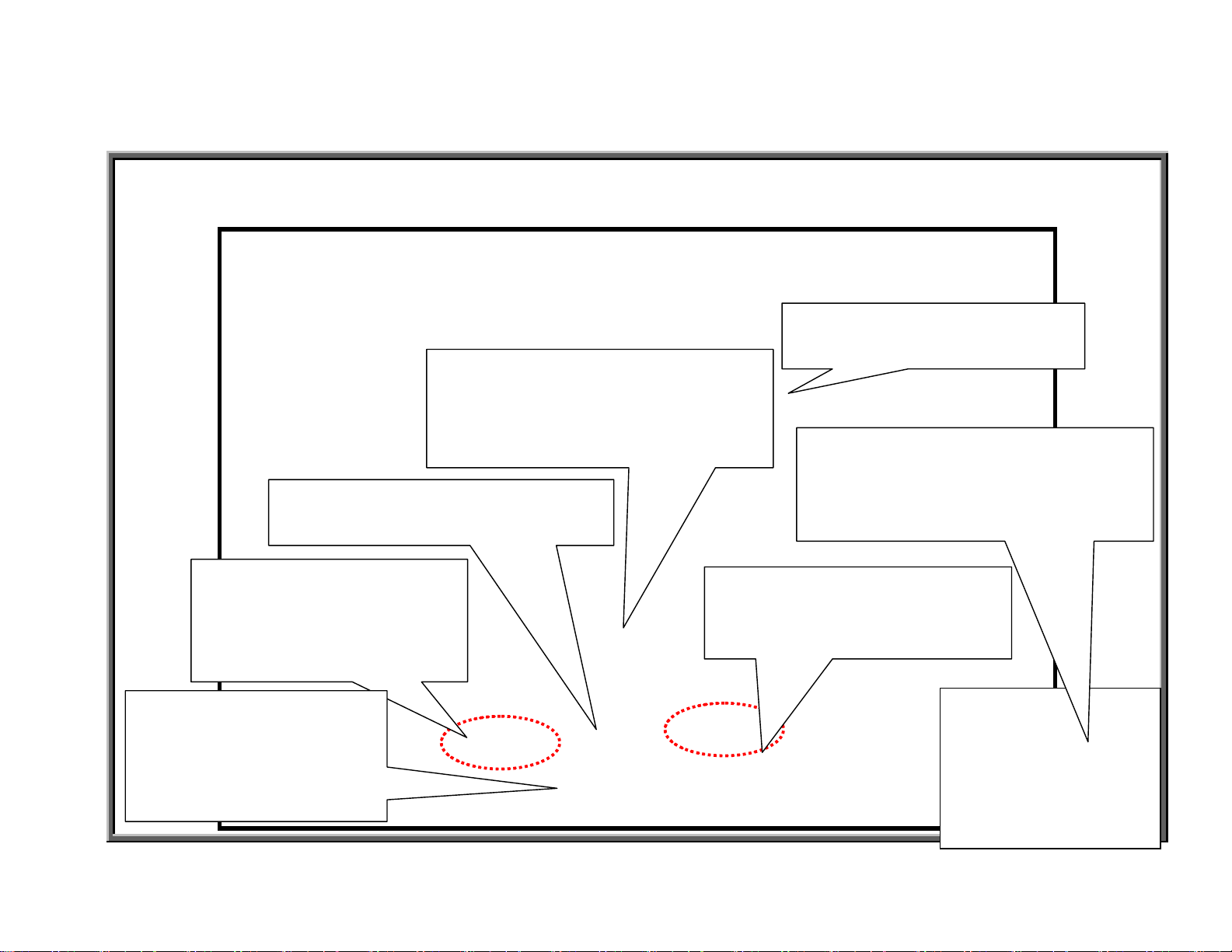
6300 Display Windows
65% Target Heart Rate Window
Î Shows 65% target heart rate
HEART RATE Window
Î Shows actual heart rate
DISTANCE & INCLINE Window
ÎDISTANCE: Shows distance
when indicator is lit
ÎINLCINE: Shows incline
position when indicator is lit
SPEED & METS Window
ÎSPEED: Shows treadmill
speed when indicator is lit.
ÎMETS: Shows Metabolic
Equivalency Table (METS)
when indicator is lit.
CALORIES & CAL/HR Window
ÎCALORIES: Shows calorie
expenditure when indicator is lit.
ÎCAL/HR: Shows calorie
expenditure per hour when
indicator is lit.
80% Target Heart Rate Window
ÎShows 80% target heart rate
72.5% Target Heart Rate Window
ÎShows 72.5% target heart
TIME & PACE Window
ÎTIME: Shows duration of
exercise time when indicator
is lit.
ÎPACE: Shows minutes per
mile when indicator is lit.
6300 INTRO.03

6300/6310 Treadmill Electronics Repair Manual – 6300 Introduction
6300 Display Keys
<CHANGE> Key
Î Press to change modes: Distance/Incline;
Calories/Cal/Hr; Time/Pace; Speed/METS
<ENTER> Key
ÎPress to confirm your choice.
INCLINE<▲>/<▼> Key
EMERGENCY STOP Knob
ÎPress to stop in an
emergency. Twist to reset.
Workout settings will be cleared.
(Prior to Sept. 2004)
ÎPress INCLINE <▲> to
increase incline. Press <▼>
to decrease incline.
STOP Key
ÎPress to stop the unit. Press
again to restart the unit. Workout
memory will be retained.
SPEED<▲>/<▼> Keys
ÎPress <▲> to increase or <▼>
to decrease unit speed.
6300 INTRO.04
6300/6310 Treadmill Electronics Repair Manual – 6300 Introduction
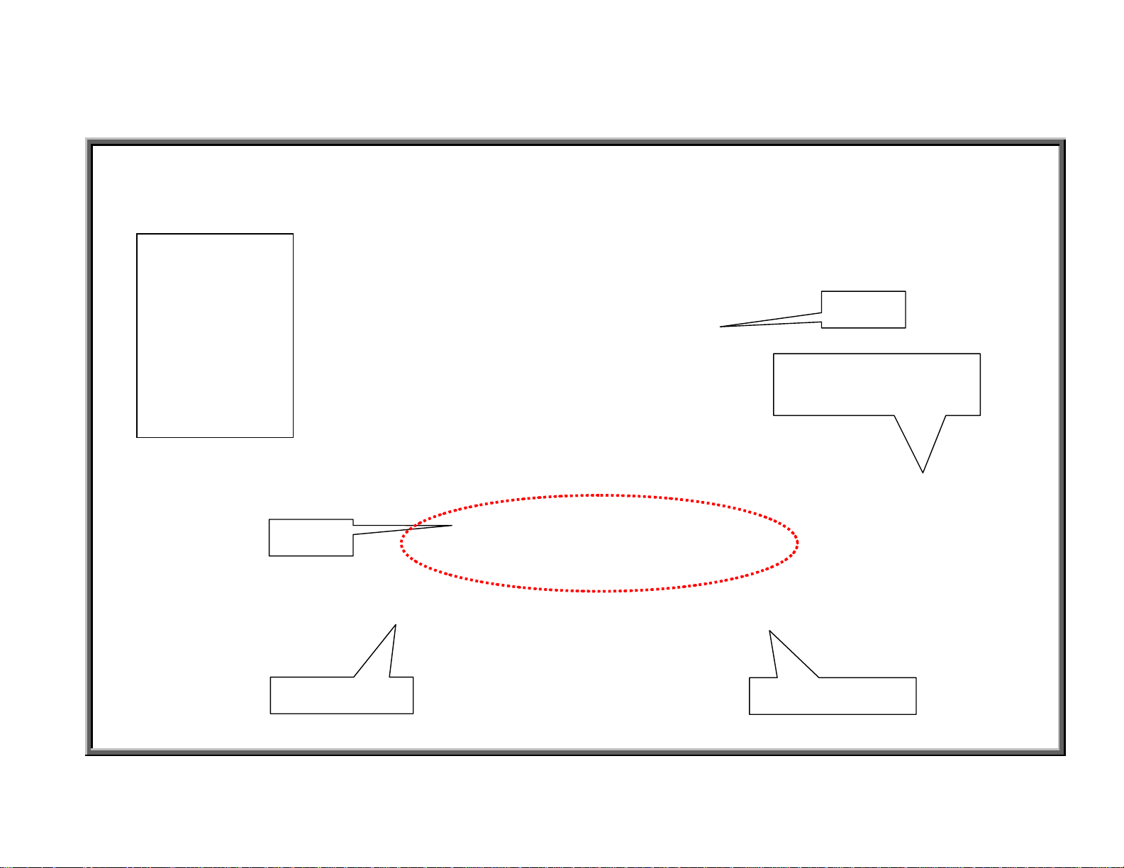
6300 Display Unit Feedback LEDs
Note: This picture shows an old
display without exercise
programs. Programs were
added May 2004.
Motor Overheat LED
ÎLights to indicate that the motor is too hot.
Inspect the motor.
6300 INTRO.05

6300/6310 Treadmill Electronics Repair Manual – 6300 Introduction
Operating the 6300 Treadmill: Start Up
Quick Start: Turn on the On/Off switch. On/Off Switch LED lights up. Display lights up.
“6300” scrolls across the lower windows. Press Speed <▲> key.
Start with Personalized Settings
1. Start Up: Turn on the On/Off switch. On/Off Switch LED lights up. Display lights up.
“6300” scrolls across the lower windows. Press any key except Speed <▲> key.
2. Age Setting: Age LED lights up. A number appears in the distance/incline window. Press
incline <▲> or <▼> key to change the age setting. Press ENTER key to confirm your choice.
3. Weight Setting: Weight LED lights up. A number appears in the distance/incline window.
Press incline <▲> or <▼> key to change the weight setting. Press ENTER to confirm your choice.
6300 INTRO.06

6300/6310 Treadmill Electronics Repair Manual – 6300 Introduction
Operating the 6300 Treadmill: Manual Mode
Manual Operation: Manual mode is the default for this product. Manual LED lights up.
Press other keys to directly operate the unit.
Speed: Press Speed <▲> key to increase speed. Speed window shows increasing speed value.
Press Speed <▼> key to decrease speed. Speed window shows decreasing speed value.
Speed measurement units are determined by the IC. Pressing keys will not change MPH to KPH.
Speed range: 0.1 to 12.0 MPH (or 0.2-20.0 KPH, European models).
Incline: Press INCLINE <▲> key to raise incline. Incline window shows increasing incline
values. Incline motor operates up. Press INCLINE <▼> key to lower incline. Incline window shows
decreasing incline values.
Incline range: 0-15%.
Change Key: Press to change mode window settings. One setting shows distance, calories, time,
speed. The other setting shows incline, cal/hr, pace, METs.
6300 INTRO.07

6300/6310 Treadmill Electronics Repair Manual – 6300 Introduction
Operating the 6300 Treadmill: Stop Functions
STOP/PAUSE Key
Pause function: Press the STOP/Pause key once. Display beeps once. Values such as calories
remain on display. SPEED/METS window flashes “0.0”. Press speed up to resume your workout.
Display beeps once. Values such as calories are retained.
Clear function: Hold the STOP/Pause key for three seconds. Display beeps once. All values clear.
Unit reverts to start up mode. “6300” scrolls across the lower windows.
EMERGENCY STOP Knob
Emergency Stop Function: Press the emergency stop knob. Display beeps once. Emergency
stop indicator lights. Lower window shows “----”.
Reset Function: Rotate the emergency stop knob clockwise. Display beeps once. Emergency
stop indicator extinguishes. Unit reverts to start up mode. “6300” scrolls across the lower windows.
Note: The emergency stop knob was eliminated Sept. 2004. To update an old unit, eliminating the
stop knob, you need two things: A jumper, which goes into the stop knob wire connector on the display,
and a plastic sticker, which covers the hole where the stop knob sat.
6300 INTRO.08

6300/6310 Treadmill Electronics Repair Manual – 6310 Introduction
6310 Introduction –
6310 – INTRODUCTION.01 – 6310 Treadmill Specifications at a Glance
6310 – INTRODUCTION.02 – 6310 Display Windows
6310 – INTRODUCTION.03 – 6310 Display Keys
6310 – INTRODUCTION.04 – 6310 Display Unit Feedback LED
6310 – INTRODUCTION.05 – Operating the 6310 Treadmill: Start Up
6310 – INTRODUCTION.06 – Operating the 6310 Treadmill: Manual Operation
6310 – INTRODUCTION.07 – Operating the 6310 Treadmill: Stop Functions
6310 – INTRODUCTION.08 – Operating the 6310 Treadmill: Programs
6310 – INTRODUCTION.09 – Operating the 6310 Treadmill: KPH/MPH, Distance/Time, Clear
6310 Treadmill Features
6310 INTRO.00
6300/6310 Treadmill Electronics Repair Manual – 6310 Introduction
6310 Treadmill Specifications at a Glance
Function Description
Operation Modes Manual; Programs: college track, climber’s trek, bay run, river run; Interval 1:1; Int erv al 1:2.
Programs originally had a set 30-minute length; Time settings were added Jan. 2004.
Heart Rate (HR) Function POLAR transmitter and heart touch rate (HTR)
Heart Rate Control (HRC) Heart rate target values: 65%; 72.5%; 80%
Display – Dot Matrix 30 x 16 dot
1.Distance / Incline (Board revised Feb. 2003 because incline stuck.)
Display - Digital Windows
Display - Keypad PET touch type, Sept. 2003
Emergency Stop Emergency stop knob on display (removed Sept. 2004); pause/stop key on keypad
Drive Board Revised June 2004 (new is V3.2) after motor brush change
Motor Spee d 0.1-12.0 MPH (North America standard); 0.2-20.0 KPH (Europe)
Motor Highest Speed 2900 RPM
Motor Horse Power Originally 3.2 HP; revised to 4.0 Sept. 2003 with ribb ed exterior
Motor Thermal Switch Turns on “Service” indicator if motor gets too hot (Sept. 2003)
Incline Range 0-15%
Incline VR Calibration 0% position = 1.20 VDC; measured on VR blue and green wires
Units: MPH/KPH Can be set by key sequence: See 6310 INTRO.08.
Power Requirements 120 VAC, 20 AMP dedi cated (Europe: 220 VAC)
Frame Color: Originally gray, became silver Nov. 2004
2.Calories / HR
3.Time / Pace
4.Speed / Mets (Display became C-Safe compatible Dec. 2004)
6310 INTRO.01
6300/6310 Treadmill Electronics Repair Manual – 6310 Introduction
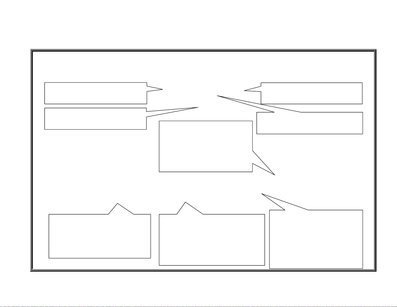
6310 Display Windows
65% Target Heart Rate Window
ÎShows 65% target heart rate
HEART RATE Window
ÎShows actual heart rate
Dot Matrix “Main” Window
ÎShows scrolling messages
DISTANCE & INCLINE Window
ÎDISTANCE: Shows distance
when indicator is lit.
ÎINCLINE: Shows incline
position when indicator is lit.
SPEED & METS Window
ÎSPEED: Shows speed when
ÎMETS: Shows Metabolic
CALORIES & CAL/HR Window
ÎCALORIES: Shows calorie
expenditure when indicator is
lit.
ÎCAL/HR: Shows calories per
hour when indicator is lit.
80% Target Heart Rate Window
ÎShows 80% target heart rate
72.5% Target Heart Rate Window
ÎShows 72.5% target heart rate
indicator is lit.
Equivalency Table (METS) when
TIME & PACE Window
ÎTIME: Shows duration of
exercise time when
indicator is lit.
ÎPACE: Shows minutes per
mile or kilometer when
indicator is lit.
6310 INTRO.02
6300/6310 Treadmill Electronics Repair Manual – 6310 Introduction
6310 Display Keys
<SCROLL> Key
ÎPress to select programs.
<CHANGE> Key
Î Press to change modes:
Distance/Incline; Calories/Cal/Hr;
Time/Pace; Speed/METS
<ENTER> Key
ÎPress to confirm your selection.
EMERGENCY ST OP Key
ÎPress to stop in an emergency;
Twist to reset. Workout settings will
be cleared. (Removed Sept. 2004)
INCLINE<▲>/<▼> Keys
ÎPress INCLINE<▲> to
increase incline. Press <▼>
STOP/PAUSE Key
ÎPress to stop the unit.
Press again to restart the
unit. Workout memory will
be retained.
SPEED<▲>/<▼> Keys
ÎPress <▲> to increase or
6310 INTRO.03
6300/6310 Treadmill Electronics Repair Manual – 6310 Introduction
6310 Display Unit Feedback LED
Motor Overheat LED
ÎLights to indicate that the motor is
too hot. Inspect the motor.
Note: This shows the old,
30-minute exercise programs
in units before Jan. 2004.
6310 INTRO.04

6300/6310 Treadmill Electronics Repair Manual – 6310 Introduction
Operating the 6310 Treadmill: Start Up
Quick Start: Turn on the On/Off switch. On/Off Switch LED lights up. Display lights up.
“SPORTSART” scrolls across the top of the main window. “6310” appears in the lower part of
the main window. Press SPEED <▲> key.
Start Up with Personalized Settings
1. Start Up: Turn on the On/Off switch. On/Off Switch LED lights up. Display lights up.
“SPORTSART” scrolls across the top of the main window. “6310” appears in the lower part of
the main window. Press any key except SPEED up.
2. Age Setting: Age LED lights. “PRESS INCLINE ▲▼ TO INPUT YOUR AGE, PRESS
ENTER…” scrolls across the top of the main window. “AGE” appears in the lower part of the main
window. Press incline <▲> or <▼> key to set age. Press ENTER key to confirm your choice.
3. Weight Setting: Weight LED lights. “PRESS INCLINE TO INPUT YOUR WEIGHT, PRESS
ENTER…” scrolls across the top of the main window. “LB” or “KG” appears in the lower part of
the main window. A number appears in the distance/incline window. Press incline <▲> or <▼>
key to change the weight setting. Press ENTER key to confirm your choice.
4. Manual Operation: “PRESS SPEED <▲>” scrolls across the main window. The SPEED LED
lights. “0.0” flashes in the SPEED/METS window. In the program area, the MANUAL indicator lights.
Press SPEED<▲> key. Treadmill walk belt starts moving.
6310 INTRO.05

6300/6310 Treadmill Electronics Repair Manual – 6310 Introduction
Operating the 6310 Treadmill: Manual Operation
To enter manual mode, press the SCROLL key until the MANUAL indicator
lights. Manual mode provides direct control over speed, incline, and other functions.
Speed: Press Speed <▲> key to increase speed. Speed window shows increasing speed value.
Press Speed <▼> key to decrease speed. Speed window shows decreasing speed value.
Speed measurement units are determined by the IC. Pressing keys will not change MPH to KPH.
Speed range: 0.1 to 12.0 MPH (or 0.2-20.0 KPH, European models).
Incline: Press INCLINE <▲> key to raise incline. Incline window shows increasing incline
values. Incline motor operates up. Press INCLINE <▼> key to lower incline. Incline window shows
decreasing incline values.
Incline range: 0-15%.
Change Key: Press to change mode window settings. One setting shows distance, calories, time,
speed. The other setting shows incline, cal/hr, pace, METs.
6310 INTRO.06

6300/6310 Treadmill Electronics Repair Manual – 6310 Introduction
Operating the 6310 Treadmill: Stop Functions
STOP/PAUSE Key
Pause function: Press the STOP/Pause key once. Display beeps once. Workout memory values,
such as calorie expenditure, remain on display. SPEED indicator lights. SPEED/METS window
flashes “0.0”. Press speed up to resume your workout. Display beeps once. Workout memory,
including calorie expenditure, etc., is retained.
Clear function: Hold the STOP/Pause key for three seconds. Display beeps once. All values clear.
Unit reverts to start up mode. “SPORTSART” scrolls across the upper part of the main window.
“6310” appears in the lower part of the main window.
Emergency Stop Knob
Emergency Stop Function: Press the emergency stop knob. Display beeps once. All values clear.
All functions stop. “RESET EMERGENCY STOP BUTTON” scrolls across main window.
Reset Function: Rotate the emergency stop knob clockwise. Display beeps once. Unit reverts to
start up mode. “SPORTSART” scrolls across the upper part of the main window. “6310” appears
in the lower part of the main window.
Note: The emergency stop knob was eliminated Sept. 2004. To update an old unit, eliminating the
stop knob, you need two things: A jumper, which goes into the stop knob wire connector on the display,
and a plastic sticker, which covers the hole where the stop knob sat.
6310 INTRO.07
6300/6310 Treadmill Electronics Repair Manual – 6310 Introduction
Operating the 6310 Treadmill: Programs
Press the Scroll<▼> key to select programs. A program indicator lights. The next program indicator
down lights each time the scroll key is pressed. Press the ENTER key to confirm your choice.
Then press the SPEED <▲> key. The incline position appears graphically on the main window.
Secondary windows show workout values.
Note: This shows the old,
30-minute exercise programs
in units before Jan. 2004.
Time can now be set when
you input the program
settings.
6310 INTRO.08

6300/6310 Treadmill Electronics Repair Manual – 6310 Introduction
KPH/MPH, Distance/Time, Clear
Set MPH/KPH: Turn on the unit. “SPORTSART” scrolls across the main window. “6310” appears in the lower part of the main
window. Hold the CHANGE key down three seconds. “PRESS TO SELECT MPH/KPH, PRESS ENTER” scrolls
across the top part of the main window. “MPH” or “KPH” appears on the lower part of the main window. Press <▲> and
<▼> keys to toggle between MPH and KPH. When your choice appears, press the ENTER key to confirm your selection.
See Distance/Time: “PRESS ▲▼ TO SELECT MODIFY HRC TARGET HR (Y/N)?, PRESS ENTER” scrolls across
the top part of the main window. “NO” or “YES” appears on the lower part of the main window. Press <▲> and <▼>
keys to toggle between “no” and “yes”. Select your choice. Press ENTER key to continue.
Distance: A four-digit number appears over the word “MILE” (KM if in metric mode). “TOTAL DISTANCE” scrolls
across the main window. This is the distance of unit operation. Press ENTER key to continue.
Time: A four-digit number appears over the word HOUR. “TOTAL TIME” scrolls across the main window. This is the
total time of unit operation. Press ENTER key to continue.
Start Up: Unit enters start up mode. “SPORTSART” scrolls across the top part of the main wind ow. “6310” appears in
the lower part of the main window.
To Clear Time/Distance: In start up mode, press STOP/PAUSE and ENTER keys for one second. “PRESS ▲▼ TO
SELECT CLEAR TOTAL DISTANCE & TIME (Y/N)?, PRESS ENTER” scrolls across the top of the main screen.
“NO” or “YES” appears on the bottom of the main screen. Press <▲> <▼> keys to select “YES” to delete the time and
distance or select “NO” to preserve the present distance/time memory. Press ENTER key to confirm your choice.
6310 INTRO.09

6300/6310 Treadmill Electronics Repair Manual - Operation
6300/6310 Operation – Explains 6300/6310 Operation in General
OPERATION.01 – 6300/6310 Power/Signal Diagram
OPERATION.02 – 6300/6310 Power/Signal Flow Explanation
OPERATION.03 – 6300/6310 Motor Compartment Components
OPERATION.00
6300/6310 Treadmill Electronics Repair Manual – Operation
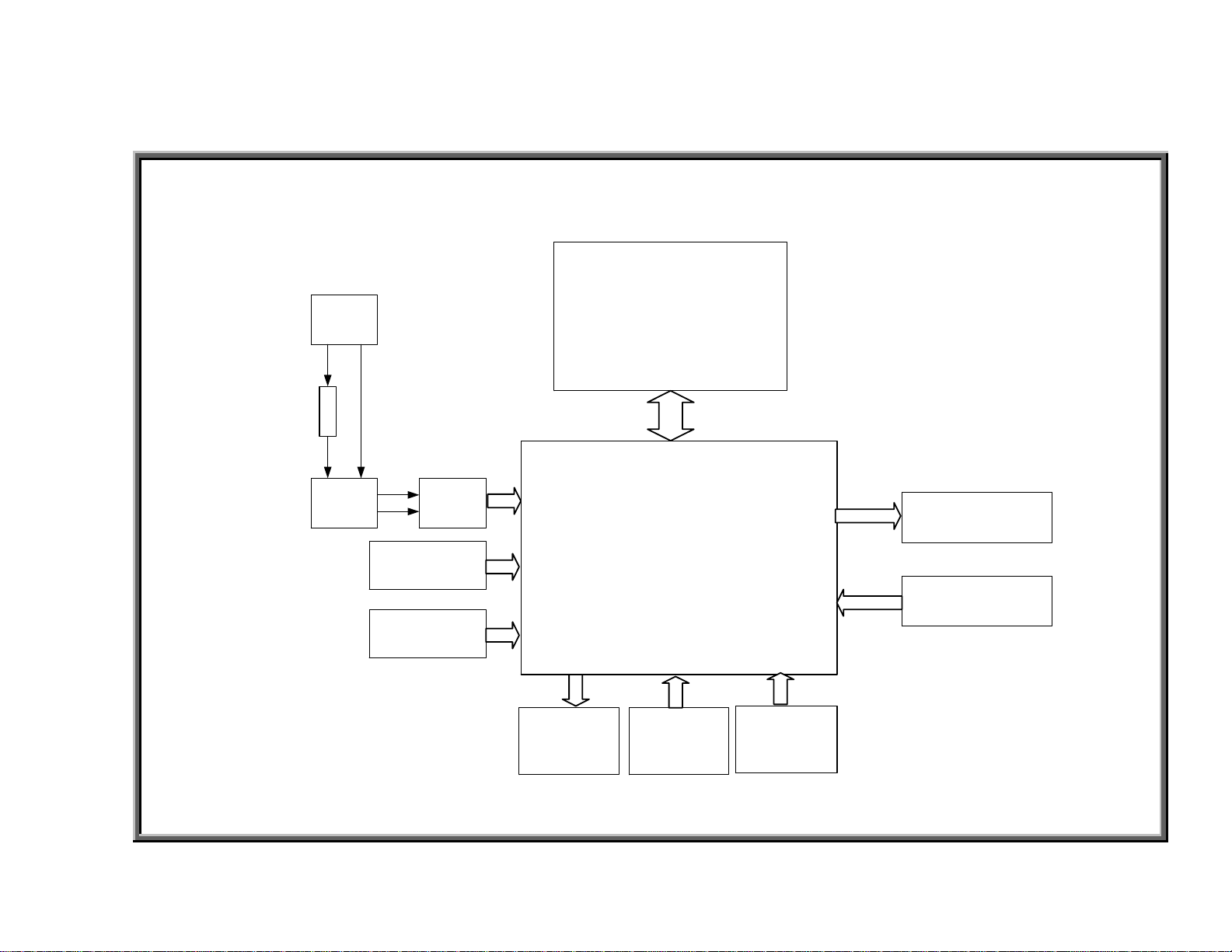
6300/6310 Power/Signal Diagram
Power
Cord
FUSE
On/Off
Switch
EMI
Filter
Inductor
Transformer
Motor
Display Board
Drive Board
Thermal
Fuse
Stride Motor
VR
Optic Sensor
OPERATION.01

6300/6310 Treadmill Electronics Repair Manual – Operation
6300/6310 Power/Signal Flow Explanation
1. AC voltage travels through the power cord, fuse, on/off switch, EMI filter, into the drive board.
2. AC voltage travels from the drive board to the transformer. The t ransformer outputs lower levels of AC voltage.
3. The drive board processes the AC voltage into DC voltage for use by the display, drive motor, and incline motor.
4. When the user presses a key, a signal travels from the keypad to the main program in the display, where it is
processed.
5. The display board sends a command via the ribbon cable to the drive board.
6. The drive board provides DC voltage to motors as directed by the display. For example, when you press
the Speed Up key, the signal travels from the display to the drive board via the ribbon cable; the drive board
emits voltage for drive motor operation. Similarly, when you press the Incline Up key, the drive board emits
voltage for incline motor operation.
7. On both the drive motor and incline motor are sens ors which tell the display about motor operation. Thei r signals
travel to the drive board, up the ribbon cable, to the display.
8. On the drive motor is an optic sensor. As the drive motor rotates, the opt ic sensor wheel rotates. The sensor
detects the difference between optic wheel teeth and spaces, thus indicating speed.
9. On the incline motor is a variable resistor (VR). As the incline motor turns, the VR turns, and its output voltage
changes, thus indicating the incline position.
10. The display uses sensor signals to determine whether to command the drive board to continue providing or
shut off power to the motors.
The Role of Other Parts
1. The inductor ensures steady current to the drive motor.
2. The thermal fuse on the drive motor is activated if the motor becomes too hot. When the thermal fuse is
activated (the circuit stops conducting), the “service required” indicator on the display lights.
3. The Electro Magnetic Irradiation (EMI) filter prevents interference to other products.
OPERATION.02
6300/6310 Treadmill Electronics Repair Manual – Operation
6300/6310 Motor Compartment Components
Drive Motor
Note: Old drive motor
is shown. New ones
have ribs for heat
dissipation. Change
occurred Sept. 2003.
Optic Sensor Wheel
Optic Sensor Board
Transformer
EMI Filter
Incline VR
Incline Motor
Inductor (not shown)
OPERATION.03
Drive Board
 Loading...