

Sportop E7000P PLUS Owner's Operating Manual

E7000P PLUS

- 1 -
Main frame
Monitor
TOOLS
Front stabilizer
Rear stabilizer
Central
support tube
Front
handlebar
Side
handlebar
Water
bottle
Handlebar joint cover
Pedal tube joint cover Pedal
(H1)
(H2)
(H3)
(H4)
(H5)
(H6)
(J1) Knob (J2) Screw M5x8L (J3) Screw M4x12L (J4) Washer M6
(J5) Spring washer M6 (J6) Knob (J10) Iron bracket
-2-
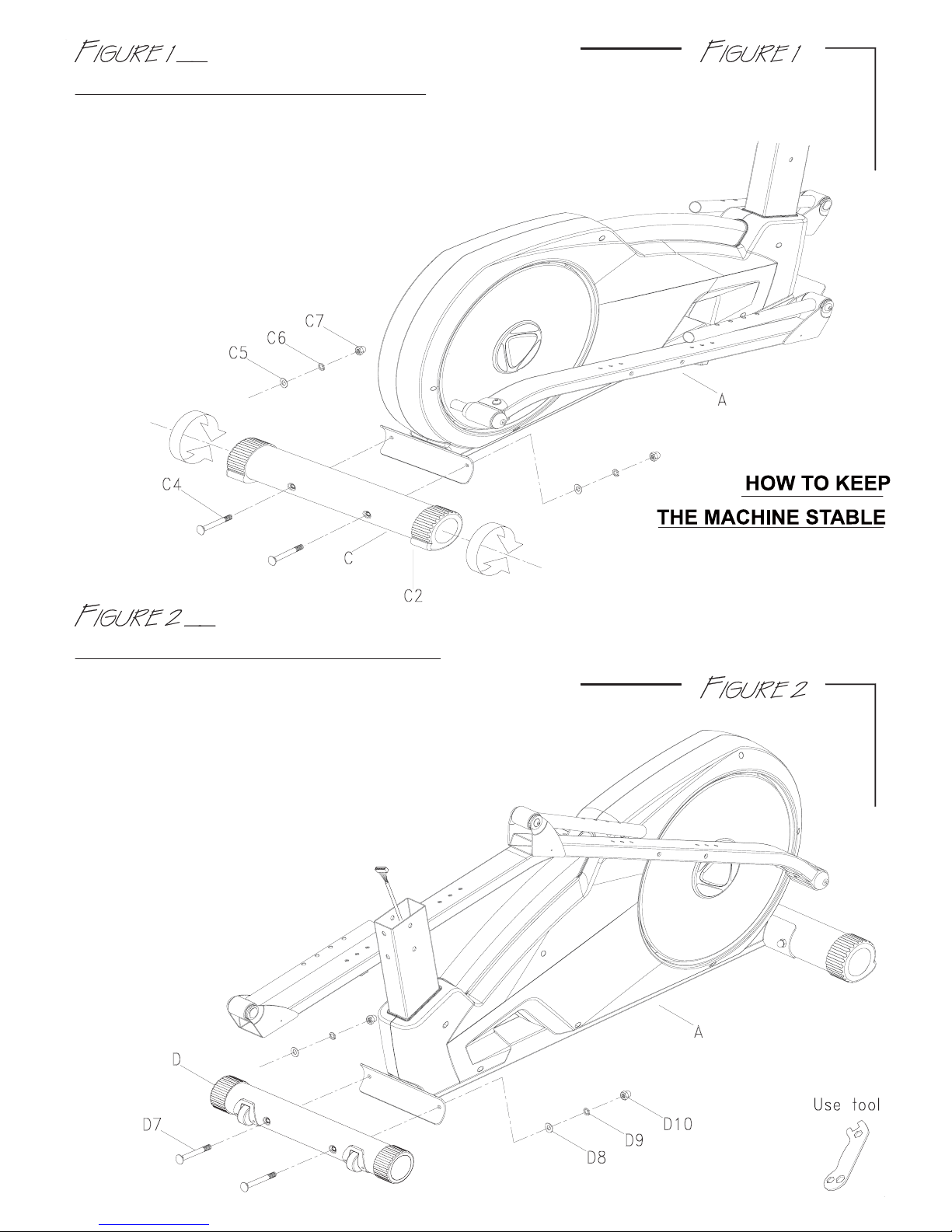
ASSEMBLY FOR REAR STABILIZER
Then, secure it with washer(C5), spring washer(C6) and nut(C7).
After you complete Figure 1 & 2,
if the machine dose not sit level,
you can use the adjustable end
caps(C2) to compensate for
uneven floors.
Then, secure it with washer(D8), spring washer(D9) and nut(D10).
ASSEMBLY FOR FRONT STABILIZER
First, remove the bolts(C4), washer(C5) and nuts(C6) from the rear stabilizer(C).
Use two bolts(C4) through the rear stabilizer(C) to attach to the bracket
at the back of the main frame(A).
First, remove the bolts(D7), washer(D8) and nuts(D9) from
the front stabilizer(D).
Use two bolts(D7) through the front stabilizer(D) to attach to the bracket
at the back of the main frame(A).
- 3 -
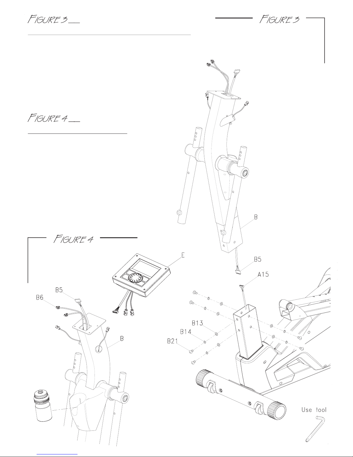
First, remove the bolts(B21), spring washers(B14) and washer(B13) from the
central support tube(B).
ASSEMBLY FOR CENTRAL SUPPORT TUBE
Step1. Connect the cable(B5) & (A15).
Step2. Assemble the central support tube(B)
onto the main frame(A) with bolts(B21), spring
washer(B14) and washer(B13).
Attention:
when pushing the tubes
together make sure not
to pinch the cables.
ASSEMBLY FOR MONITOR
Step1. Connect the sensor wire(B5 & B6) with
monitor wires and put the monitor on the
fixing plate.
Step2. You can place the water bottle in the
plastic water bottle holder.
- 4 -
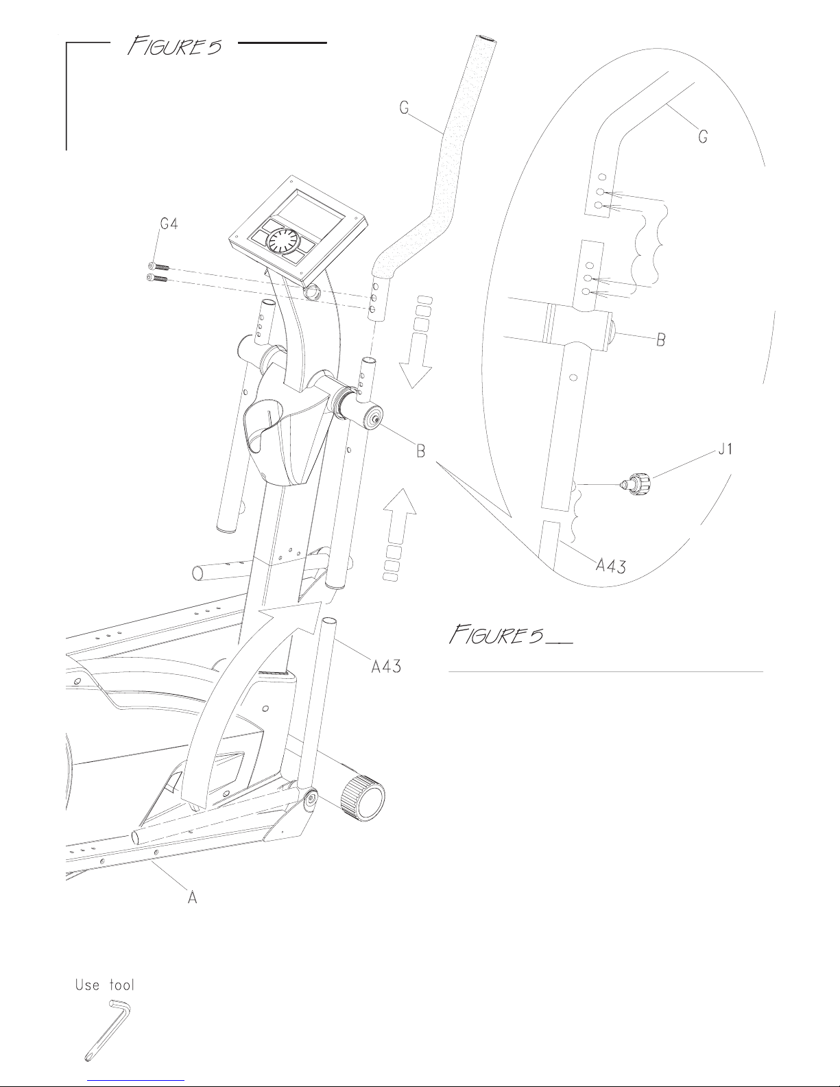
Step1. Pull up right or left connect tube(A43)
and adjust the suitable position which 4 holes
are available when loosing the pop-pin
the middle tube(B) and lower tube(A43) will be
fixed securely.
Step2. First, remove the bolts(G4), from
the side handlebar(G).
ASSEMBLY FOR SIDE HANDLEBAR
contrastive
drawing for
the (G4)
assembly
position.
for the (J1)
assembly
position.
Step3. Then, slide the side handlebar(G) over
central support tube(B).
Secure with bolts(G4).
** During handlebar assembly you have
to use the holes as pictured in close-up
view.
Repeat step1 and 2 on left connect tube(A43).
 Loading...