

2.4GHZ Digital Wireless
Microphone System
USER GUIDE

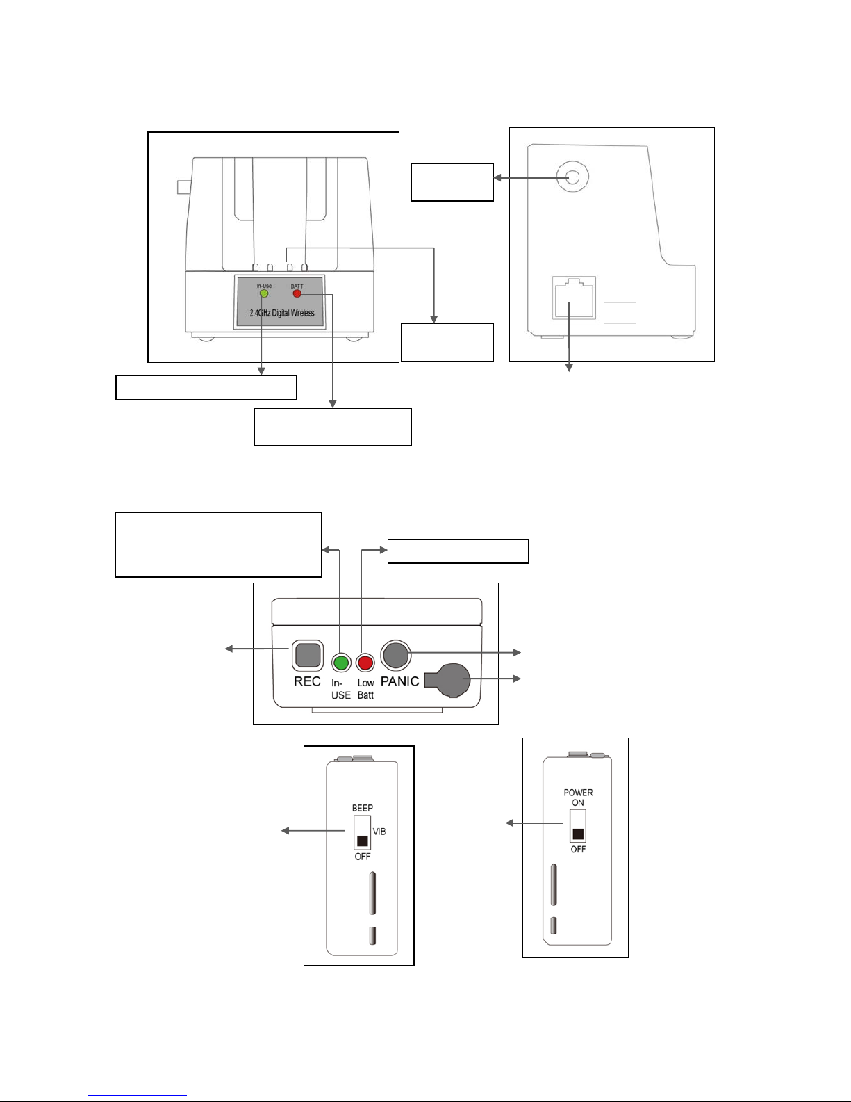
DESCRIPTION
Docking Station (Receiver)
Transmitter
Green LED: In-use (Record)
Red LED: Charging
Green LED: Fully charged
Terminal
for charging
Antenna
Connector
Audio Out cable
REC Button
(Trigger 1)
Lapel Mic. Cover
EMG Button (Trigger 2)
Green: In-use (Light On)
REC Button ON (Flashing)
REC Button OFF (Light On)
RED LED: Out of Range
Red LED: Low Battery
Audible and Vibration
Selectable Switch
Power On/Off
Switch

1. QUICK SET UP AND OPERATION
Synching Up the Transmitter and Receiver
The synch operation only needs to be performed the first time a system is used, or a new Transmitter is used
with a Receiver previousl y synched to another Transmitter. Do not perform the synch operation multiple
times; it only needs to be done one time when a n ew Transmitter is used with a new Receiver.
1) Turn the Transmitter power switch to ON and place the Transmitter in the recharge cradle of the
Receiver. The Transmitter goes in the Receiver with the belt clip facing out.
2) The recharge LED will light (Green if fully charged, Red if charging). Leave the Transmitter in the cradle
for 4 hours for a full charge.
3) Press the REC button on the transmitter and hold until the In-Use LED on the Transmitter and Receiver
start to flash, then release the button.
4) After a few seconds the light will stop flashing, and a beep will sound (If the beep is enabled).
5) The transmitter and Receiver are now synched and will continue to be until another transmitter is linked
to that Receiver.
Normal Operation
1) With the transmitter synched up, remove it from the cradle, plug in the lapel microphone (if used)
and place the transmitter on your belt.
2) When you remove Transmitter from the cradle, The TR and Receiver’s In-USE LED wi ll li gh t a
constant
Green and you will hear short beep. To start the recording, press the REC button and the In-Use
LED will blink in green.
3) To end recording, press the REC button and the In-Use LED will light a constant green.
4) At the end of your shift turn the transmitter off and replace it in the charging cradle.
Out of Range
1) The transm itter will alert you with Audible warning beeps (two tone) and the In-Use LED wil l blink in
red.
2) Move closer to the Receiver and the link will be re-established once you return to normal
range. The In-Use LED will light constant green when link is back to normal operation.
3) If the link is not re-established within 30 seconds, the transmitter and receiver will return to standby
mode.
4) If you went out of range in Standby mode, or the unit reverted to standby mode, re-enter normal range
and press the In-Use button. Operation will return to normal.
5) If you will be out of range for a long period of time, turn the Receiver off.
Low Battery Warning
1) If the transmitter Low BATT indicator (red) starts flashing or you hear warning beeps, return the
transmitter to its cradle on the receiver to fully charge the transmitter.
2) The Charge LED indicator will light constant green when the unit is fully charged.
EMG Button (if wired the white cable to Alarm in of the BRX for use in your vehicle)
1) The EMG Button (Trigger 2) can be programmed to do many things but may not be connected in your
vehicle. Check with your technical department to understand what this button will control before you use
it.
2) In Trigger mode: Press the EMG button on the transmitter, a beep will sound and the relay will be
triggered at the receiver.
3) In Standby mode: Press the EMG button on the transmitter, a beep will sound and the relay will be
triggered at the receiver.
Disabling the Beep Sound On the Transmitter
1) All of the audible beep signals on the transmitter can be disabled by setting the BEEP switch to the
1) The REC Button (Trigger 2) can be programmed to do many things but may not be connected in your
vehicle. Check with your technical department to understand what this button will control before you use
it.
2) In Trigger mode: Press the REC button on the transmitter, a beep will sound and the relay will be
triggered at the receiver.
3) In Standby mode: Press the REC button on the transmitter, a beep will sound, the green In-Use indicator
will blink and the relay will be triggered at the receiver.
off position.
REC Button (if wired the blue cable to Alarm in of the BB for use in your vehicle)

2. INSTALLATION
PIN DESCRIPTION OF THE RECEIVER OUTPUT PORT
Connector wire (RJ45)
1. Connect Audio Output to Audio in as below,
2. Connect Power input to DC 12V output as below,
3. Connect Trigger1 and Tr i gger 2 to Alarm input, if you hope to use them.
8
1
DC 12V Power Input
Audio Output
Red: Trigger 1
Black: Trigger 2
Pin #1 : Transmitter Au dio out
Pin #2 :
Pin #3 : 12V DC_IN
Pin #4 : Ground
Pin #5 : REC Trigger OUT
Pin #6 :
Pin #7 : EMG Trigger Out
Pin #8 :
Cable DESCRIPTION (Connect these cable to the BB DVR)

3. GUIDELINES AND RECOMMENDATIONS FOR BEST PERFORMANCE
Compatibility
The transmitter and receiver must synchronize to work together (see Synch process on page 3). The synch
operation only needs to be performed the first time a system is used, or when a new Receiver is used with a
Receiver previously synched to another Receiver. Do not synch multiple times, just once until a new
Receiver is used. Any Receiver can be synchronized with any Transmitter.
Using Multiple Wireless Systems
This system has 95 possible “channels” that are really different frequency hopping schemes. Each
synchronized Receiver and transm itter will automatically find a clear channel so up to 40 systems can work
together in one location depending on other interference problems
Potential Sources of Interference
There are many potential sources of interference for your wireless system. Any electronic product that
contains digital circuitry including digital signal processors (reverb/multi-effects units), electronic keyboards,
digital lighting controllers, CD and DVD players, and computers, all emit RF energy that can adversely affect
the performance of your wireless system. It is always best to place the receiver as far away as possible from
these devices to minimize potential problems.
This system operates in the 2.4MHz ISM band and other devices in that band may interfere. The spread
spectrum technique used in this system is very robust and should operate even in the presence of other
2.4MHz devices such as walkie-talkies, LANs, cordless phones, etc. in the area.
Battery Recommendations
The Lithium-Ion batter y built into t his transmitter will work at full c apacity for over 500 charge cycles . If you
notice lower than usual battery life over time, it may be time to replace the cell
Warnings
Do not use this product in or near water, i.e. near a bathtub, sink, or swimming pool.
Do not use this product in the vicinity of a gas leak or to report a gas leak.

4. TECHNICAL SPECIFICATIONS
RECEIVER BASE STATION
Controls
Video Trigger Active +12/GND
Indicators
INUSE LED: GREEN
CHARGE LED : CHARGING -> RED
FULL CHARGED -> GREEN
RECORD LED GREEN FLASHING
Connections
In Car Mic. 2.5mm Mono Plug
Un-terminated Cord
RED +12V DC Power
BLUE Record Trigger out (Record on =DC12V, OFF= GND)
YELLOW Inside MIC Trigger IN (Ground to enable, OFF=12V)
ORANGE POWER GROUND
BLACK AUX (Panic) Trigger out (+12V when EMG is pushed, OFF=GND)
GRAY RECORD TRIGGER IN (GND= RECORD LED ON, +5V DC REC LED OFF)
Audio Connector
Tip Inside Car Mic
Ring Transmitter Audio
Sleeve Audio Ground
RF Specifications
Frequency Range: 2.4GHz
Number of Channels: 95 possible Diversity:
Internal antenna Receiver Type: FHSS
RF Sensitivity:
-102 +/-3 dBm FCC type
acceptance: Approved Part 15
Audio Specifications
Frequency Response: 200 ~ 4000Hz +/- 3 dB Audio
Output Level: 3.6Vp-p
Distortion: Less than 2% Signal to
Noise Ratio:
> 40 dB Dynamic
Range: > 50 dB
General Specifications
Range 1000feet typical Power
Supply: External 12 VDC Current
Draw: 190mA Typical
Size: 2.75in x 2.99in x 3.15in
(70mm x 76mm x 80mm)
Weight 233 g
Transmitter
Controls
On/Off Switch
Beep On/Off Switch
In Use Button Emergency
Button
Indicators
Red LED low battery indicator/Emergency indicator
Yellow LED In Use
Battery Internal Li-ion 3.7V/1300mAh cell
Battery Life 15 hours In Use with full charge
14days Standby
Battery Recharge Time 3.5 hours from full discharge
Antenna Internal
2.5mm Mic Connector Tip Signal, Sleeve Ground
Secondary Microphone Internal
RF Output 30 ~ 40 mW (typical)
Size
2.5 in. x 1.8 in. x 0.94 in.
64 mm x 46 mm x 24 mm
Weight 74 g

5. TROUBLE SHOOTING GUIDE
Problem Possible Causes Solutions
No audio and no In-Use LE D
light on the receiver when
Transmitter is on and In-use
Receiver is not powered
Make sure that the power
supply is properly connected
Transmitter and receiver not
synchronized
Turn on transmitter and place
In recharge cradle. Press the
In-use button until the In-Use
LEDs flash 3 and the fair will
be synched
No(or low) Audio with all in-Use
LEDs solid green
Lapel Microphone not connected
or positioned properly
Check the mic. connection and
Placement of the microphone
Receiver audio output cable is
Damaged or disconnected
Connect, repair or replace
cable
Interference
Another 2.4GHz device in the
Area causing interference
Push the In-Use button and
the PWW24 will automatically
select a clear channel. If the
interference is too strong,
this may not completely
eliminate it.
Shot range or drop-outs
RF reflective metal obstacles
between the transmitter and
receiver
Move the obstacles, or
reposition the receiver if
possible
In-Use LED on Receiver
flashes red and two tone
beep sounds
Transmitter is out of range Move closer to the receiver
Variable sync times or failure
to synch
Synch process run more than
one time with same pair
Power cycle the Receiver
station
and Synch one time.
6. TECHNICAL SUPPORT
For Technical Support, please contact your local distributor.
7. LIMITED WARRANTY
This product is supplied with a 1 year warranty. The Warranty excludes products that have been misused, (including
accidental damage) and damage caused by normal wear and tear. In the unlikely event that you encounter a problem
with this product, it should be returned to the place of purchase.
8. ACCESSORIES AND PA RTS
Police Wireless Microphone System
Model
DESCRIPTION
2400 T
2400 R
2400 ANT
PWC-24
PLM-24
PW24-IM
Transmitter with internal microphone, battery, belt clip
Receiver and recharge station, RJ45 cable
External ANT – 10Feet
Optional TX Charger Receiver for 24T
Lapel Microphone
In Car Microphone
 Loading...