

SPOK Aus INTELPAGE User Manual

Installation & Configuration Guide for
Intelpage IP
Amcom Software, Inc.

Copyright
Intelpage IP v2.12 Firmware
Document Version 1.0
Last Saved Date: October 10, 2013
Copyright 2003-2013 Amcom Software, Inc. All Rights Reserved.
Information in this document is subject to change without notice. The software described in this document is
furnished under one or more Program/Product License Agreements. The software may be used or copied only in
accordance with the terms of those agreements. No part of this publication may be reproduced, stored in a retrieval
system, or transmitted by any means electronic or mechanical, including photocopying and recording for any
purpose without the written permission of Amcom Software, Inc.
Amcom Software, Inc.
10400 Yellow Circle Drive
Suite 100
Eden Prairie, MN 55343
USA
Trademarks
Microsoft and Windows are trademarks of Microsoft Corporation. Other brands and their products are trademarks or
registered trademarks of their respective holders and should be noted as such.

Contents
Intelpage IP 1
Intelpage IP ......................................................................................................................... 1
Compliance Information ..................................................................................................... 1
Safety and General Information .......................................................................................... 3
About the Intelpage IP 4
About the Intelpage IP ........................................................................................................ 4
LEDs and Connectors ......................................................................................................... 5
Intelpage IP Kit .................................................................................................... 4
LED Indicators ..................................................................................................... 6
Connectors ............................................................................................................ 6
LCD Display (High Power Version Only) ........................................................... 7
Installation 8
Installation .......................................................................................................................... 8
Rack Version ...................................................................................................................... 8
Desktop Version ................................................................................................................. 9
Configuration 10
Configuration .................................................................................................................... 10
Connecting ........................................................................................................................ 10
Logging In ........................................................................................................................ 13
User Interface Fields ......................................................................................................... 14
Home .................................................................................................................. 14
Pagers ................................................................................................................. 15
Network Settings ................................................................................................ 16
Serial Port Settings ............................................................................................. 17
Transmitter Settings............................................................................................ 18
Protocol .............................................................................................................. 19
Pocsag ................................................................................................................. 21
Password ............................................................................................................. 22
IP Access List ..................................................................................................... 23
Site Survey ......................................................................................................... 24
Status .................................................................................................................. 25
Licensing ............................................................................................................ 26
Configuration Examples 28
Configuration Examples ................................................................................................... 28
Setting up Dial-in TAP to Intelpage IP from Messenger .................................................. 28
Installation & Configuration Guide for Intelpage IP Contents iii

Appendix 30
Appendix .......................................................................................................................... 30
Configuring Network Settings Through the Terminal Interface ....................................... 30
Transmitters ...................................................................................................................... 34
Installing Multiple Transmitters and Aerials ...................................................... 34
VSWR ................................................................................................................ 34
Types of Antennas ............................................................................................................ 35
Technical Specifications ................................................................................................... 36
General ............................................................................................................... 36
Desktop Version Specific ................................................................................... 36
5 Watt Rack Version Specific ............................................................................ 36
High Power Version Specific ............................................................................. 37
Intelpage IP 2 Installation & Configuration Guide for Intelpage IP

Intelpage IP
Intelpage IP
Installation
“Installation” on page 8 includes information on how to install the Intelpage IP system.
Configuration
“Configuration” on page 10 includes information on how to connect and log into the Intelpage IP system. In
addition, information on the user interface fields on the following topics are included: home, send a message, pagers,
network settings, serial port settings, transmitter settings, protocol, POCSAG, password IP access list, survey, status,
and licensing.
Configuration Examples
“Configuration Examples” on page 28 includes an example configuration for the Intelpage IP system. The
information covers how to set up a dial-in TAP to the Intelpage IP from Messenger.
Appendix
“Appendix” on page 30 includes information on cable pin-outs, technical information, and technical specifications
for the Intelpage IP product.
Compliance Information
SAA (AUSTRALIA)
To ensure compliance with ACA Technical Standards, this equipment is labeled with a Telecommunications
Compliance label. For safety reasons, this equipment should only be connected to compliant telecommunications
equipment in accordance with the manufacturer’s instructions.
FCC (USA)
Part 15
This equipment has been tested and was found to comply with FCC Rules and Regulations, Part 15 with the limits of
a Class B digital device, designed to provide reasonable protection against harmful interference. This equipment
generates, uses, and can radiate frequency energy and if not installed and used in accordance with the instructions,
may cause interference harmful to radio communications. On the base of the equipment is a label containing an FCC
Registration Number, if applicable.
Installation & Configuration Guide for Intelpage IP Intelpage IP 1

Part 90
This equipment has been tested and found to comply with FCC Rules and Regulations, Part 90.
FCCID: T5GPT5
IC (INDUSTRY CANADA, INDUSTRIE CANADA)
This class B digital apparatus complies with Canadian ICES-003. IC: 4767A-PT5
CE (EUROPE)
Amcom Software declares under our sole responsibility that the product Intelpage IP to which this declaration
relates, is in conformity with the following standards and/or other normative documents.
- EN 300 224-2 v1.1.1 (2001-01)
- EN 55022: 1994 +A1: 1995 +A2: 1997
- EN 301 489 -2 v1.3.1 (2002-08)
- EN 60950-1: 2001
We hereby declare that all essential radio test suites have been carried out and that the above named product is in
compliance to all the essential requirements of Directive 1999/5/EC.
The conformity assessment procedure referred to in Article 10(5) and detailed in Annex IV of Directive 1999/5/EC
has been followed with the involvement of the following notified body:
Bay Area Compliance Laboratory Corporation, 1274 Anvilwood Ave., Sunnyvale, CA 94089, USA
Identification mark: 1313 (Notified Body Number)
The equipment also carries the class 2 equipment identifier (exclamation mark).
The technical documentation relevant to the above equipment can be made available for inspection on application to
Amcom Software.
ROHS & WEEE
To minimize the environmental impact and take more responsibility for the world in which we live, Amcom
Software hereby confirms that the following product series comply with Directive 2002/95/EC (RoHS) and
2002/96/EC (WEEE) of the European Parliament.
Intelpage IP 2 Installation & Configuration Guide for Intelpage IP

Safety and General Information
This section includes important information on safe and efficient operation. Please read the following information
before using the unit
Exposure to Radio Frequency Energy
Your Intelpage IP contains a low power radio transmitter. When it is ON, it transmits radio frequency (RF) energy.
Your Intelpage IP is designed to comply with the following national and international standards and guidelines
regarding exposure of human beings to radio frequency electromagnetic energy (EME):
United States Federal Communications Commission, Code of Regulations; 47 CFR part 2 sub-part J
American National Standards Institute (ANSI) / Institute of Electrical and Electronic Engineers (IEEE)
C95. 1-1992
Institute of Electrical and Electronic Engineers (IEEE) C95.1-1999 Edition
National Council on Radiation Protection and Measurements (NCRP) of the United States, Report 86, 1986
International Commission on Non-Ionizing Radiation Protection (ICNIRP) 1998
National Radiological Protection Board of the United Kingdom 1995
Ministry of Health (Canada) Safety Code 6. Limits of Human Exposure to Radiofrequency Electromagnetic
Fields in the Frequency Range from 3 kHz to 300 GHz, 1999
Australian Communications Authority Radio communications (Electromagnetic Radiation-Human
Exposure) Standard 1999
To assure optimal performance and make sure human exposure to radio frequency electromagnetic energy is within
the guidelines set forth in the above standards, always adhere to the procedures outlined below.
Antenna Care
Use only the supplied or an approved replacement antenna. Unauthorized antennas, modifications, or attachments
could damage the device. Do NOT hold the antenna when the device is in use. Holding the antenna affects signal
quality and may cause the Intelpage IP to operate at a higher power level than needed. Do not use Intelpage IP with a
damaged antenna. If a damaged antenna comes into contact with your skin, a minor burn can result. The Intelpage IP
antenna port should only be connected to internal antennas located in the same building as the main equipment.
Electromagnetic Interference/Compatibility
Nearly every electronic device is susceptible to electromagnetic interference (EMI) if inadequately shielded,
designed, or otherwise configured for electromagnetic compatibility.
SELV warning
The Fusion Intelpage IP and Alarm Dispatch modules have been assessed as SELV throughout, all ports shall be
connected to approved SELV circuits or an approved isolation unit shall be used.
Potentially Explosive Atmospheres
Do not operate the Intelpage IP in any area with a potentially explosive atmosphere. Sparks in a potentially explosive
atmosphere can cause an explosion or fire resulting in bodily injury or even death. Areas with potentially explosive
atmospheres include fueling areas such as below decks on boats, fuel or chemical transfer or storage facilities, areas
where the air contains chemicals or particles such as grain, dust, or metal powders, and any other area where you
would normally be advised to turn off your vehicle engine. Areas with potentially explosive atmospheres are often
but not always posted.
Blasting Caps and Areas
To avoid possible interference with blasting operations, do not use the Intelpage IP near electrical blasting caps, in a
blasting area, or in areas posted: “Turn off two-way radio.” Obey all signs and instructions.
Installation & Configuration Guide for Intelpage IP Intelpage IP 3
About the Intelpage IP
About the Intelpage IP
The Fusion Intelpage IP is a high quality paging transmitter capable of encoding serial or TCP/IP data into
POCSAG.
Intelpage IP supports numerous industry standard protocols such as TAP (PET or IXO), COMP, SCOPE, TNPP, and
Waveware (Tekk).
Intelpage IP includes both an RJ45 Ethernet port and an RJ45 RS232 port. This enables system programming and
Ethernet or serial input from third-party systems. In addition, both ports can be used simultaneously and may be set
to different protocols, thus allowing greater flexibility.
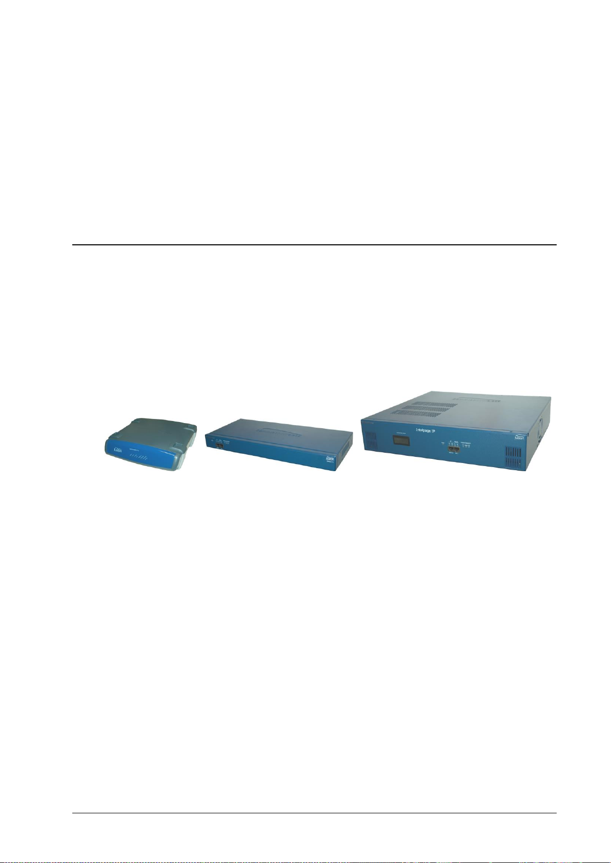
Intelpage IP Kit
Your Intelpage IP kit contains:
Intelpage IP unit
Communications cables
Green – Crossover serial cable (RJ45 to RJ45)
Black – Serial cable (RJ45 to DB9 female)
Blue – Straight through Ethernet cable (RJ45 to RJ45)
Red – Crossover Ethernet cable (RJ45 to RJ45)
An Intelpage IP Quick Setup Guide
CD containing manuals and configuration programs
Plus if you ordered a desktop version Intelpage IP:
12 VDC power supply with mains cable
Plastic wall mount bracket
Whip antenna with right angle adapter
About the Intelpage IP 4 Installation & Configuration Guide for Intelpage IP
Or if you ordered a 5 watt 19” Rack version Intelpage IP:
IEC Mains power cable
Pack including 2 x rack ears, 6 x black countersunk screws, 4 x rubber feet
N-type to BNC right angle adapter
Whip antenna
Or if you ordered a high power 19” Rack version Intelpage IP:
IEC Mains power cable
Pack including 2 x rack ears, 6 x black countersunk screws, 4 x rubber feet
NOTE: As part of the installation of your Intelpage IP 25/50/100 unit, an antenna capable of handling the power
from the rack amp is also required. The type of antenna used must be carefully chosen depending on the site and
power output of the transmitter.
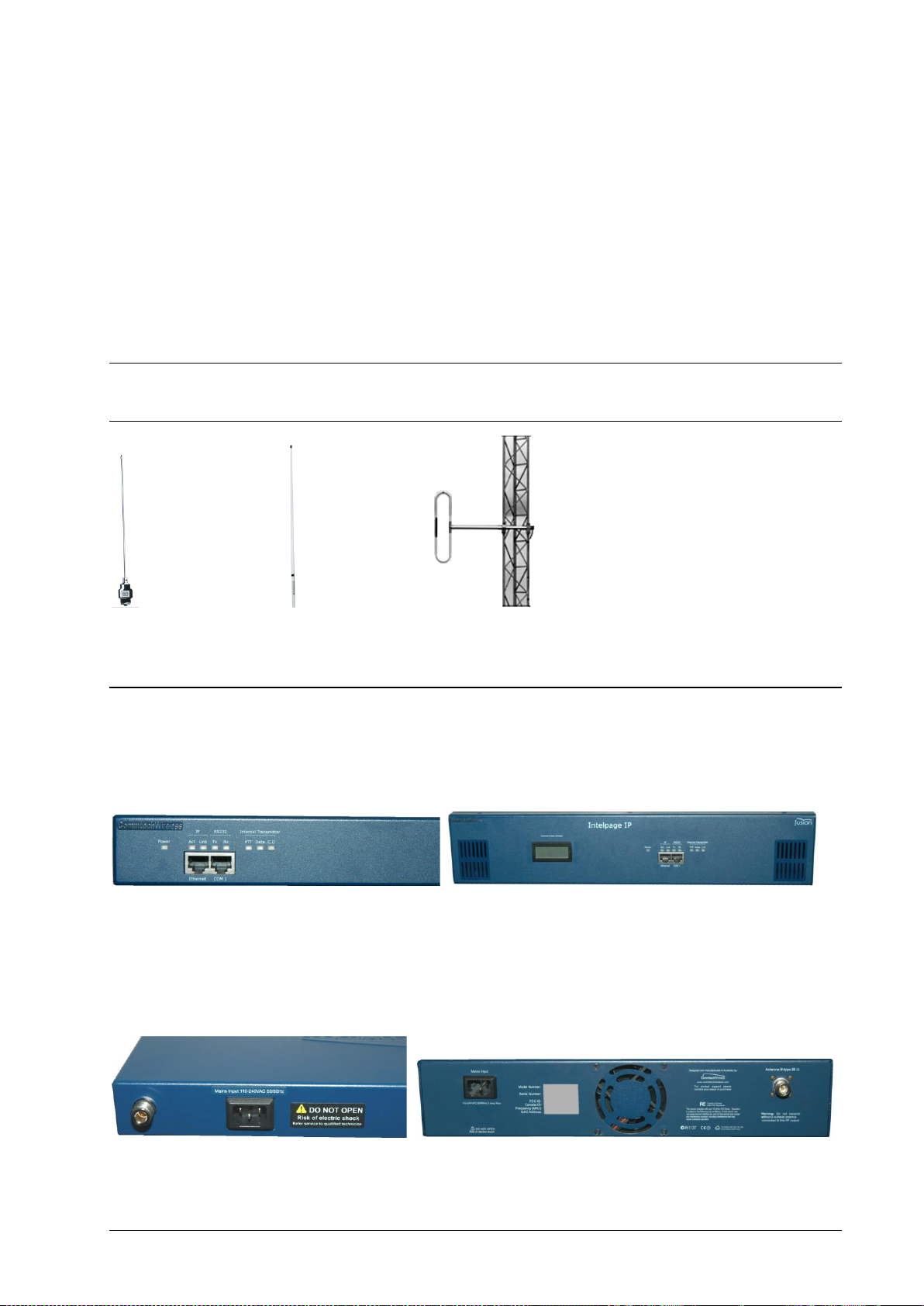
LEDs and Connectors
Depending on which type of Intelpage IP you have purchased, the connector and LED layout are slightly different.
The rack versions have all of their connectors and LEDs on the front panel as shown below.
The only exception is the mains input IEC connector and the antenna connector. You are supplied with a mains lead
in the Intelpage IP kit which plugs straight into this IEC connector.
The antenna port is an opening to allow connection of the antenna to the internal transmitter. The connector is a
standard N-type 50ohm.
Installation & Configuration Guide for Intelpage IP About the Intelpage IP 5

The desktop version has all of its LED indicators on the front panel while all of the connectors are on the rear panel.
The desktop version is supplied power via the “Power 12VDC” connector. The Intelpage IP requires 12VDC @
2amps regulated. You are supplied with a suitable power supply with mains lead which plugs straight into this
socket.
The antenna port is an opening to allow connection of the antenna to the internal transmitter. The connector is a
standard BNC 50ohm.
LED Indicators
Power Indicator
Power (Yellow) - Indicates that power is applied to the back of the unit and that it is operational.
Transmitter Indicators
Tx PTT (Yellow) - Indicates that the externally connected POCSAG transmitter is currently busy
transmitting (“Keyed up”).
Tx Data (Red) - Indicates POCSAG data activity.
C.D. (Yellow) – Indicates that the unit is initializing (may remain on for 30 seconds at startup if DHCP
is used) or indicates channel is busy (Carrier Detect).
Serial Indicators
RS232 Tx (Red) - Indicates that the receive line of the serial port is active.
RS232 Rx (Green) – Indicates that the transmit line of the serial port is active.
Ethernet Indicators
IP Activity (Green) - Indicated activity on the network.
IP Link (Green) - Indicates device is successfully connected to the network.
Connectors
Ethernet
The RJ45 Ethernet port may be used for connection to a PC, LAN, or external system for configuration and
operational purposes.
The RJ45 port on Intelpage IP is an Ethernet port like any other that may be found on a PC or network device. The
Intelpage IP supports 10Mbps Ethernet connections.
If the Intelpage IP is to be connected to a PC network (i.e. into a switch or hub), then a straight-through cable should
be used. A straight through Ethernet cable is included in the package (blue cable).
If the Intelpage IP is to be connected directly to a single PC or directly to another Ethernet enabled Fusion Series
product, an RJ45 crossover cable should be used. An Ethernet crossover cable is included in the package (red cable).
NOTE: Ensure that the switch/PC you are connecting the Intelpage IP to is set to auto-negotiate the link speed,
otherwise set it to 10Mbps half-duplex.
About the Intelpage IP 6 Installation & Configuration Guide for Intelpage IP
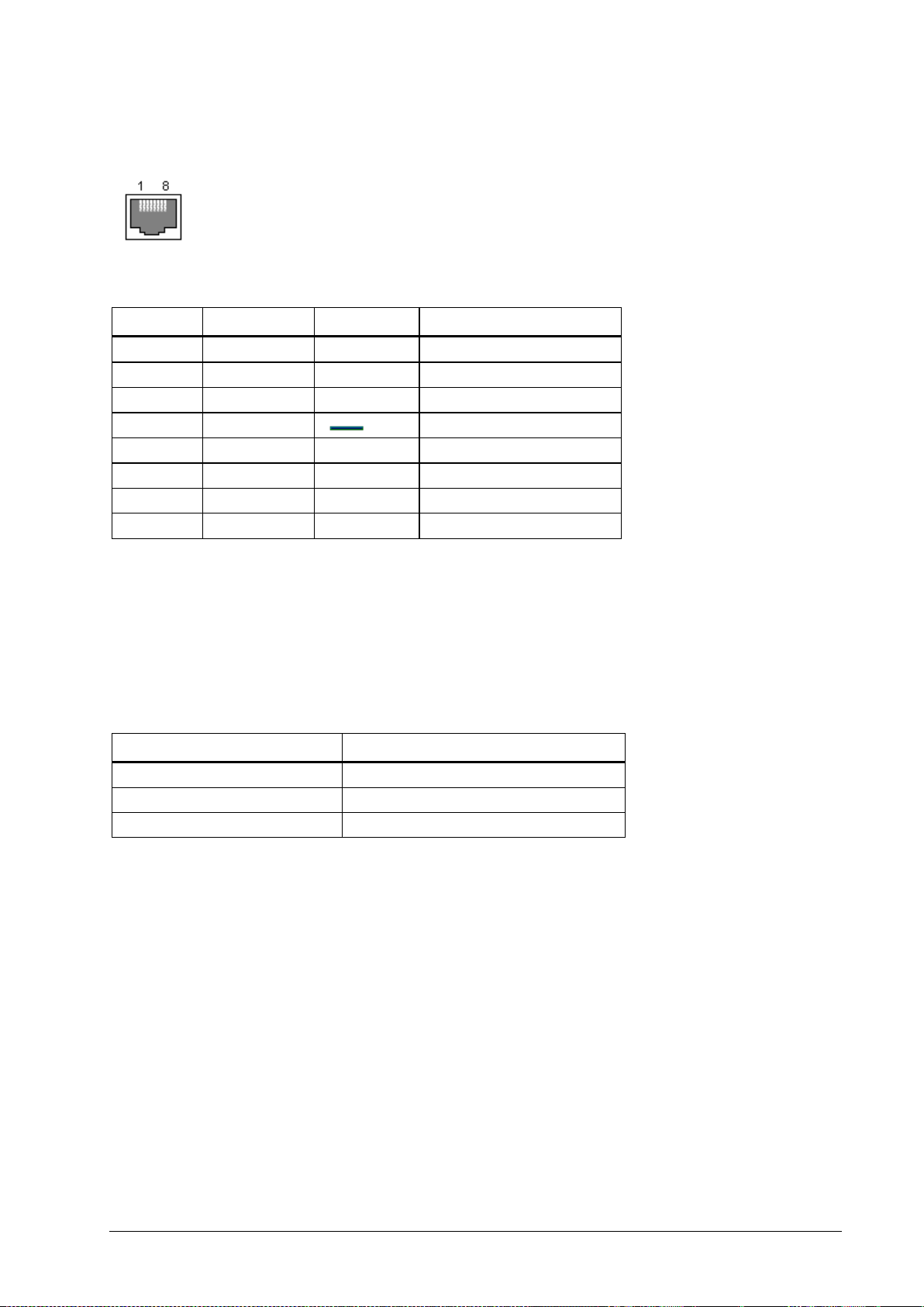
Pin No.
Name
Dir
Description
1 2 3 4
GND
System Ground
5
RXD
IN
Receive Data
6
TXD
OUT
Transmit Data
7
CTS
IN
Clear to Send
8
RTS
OUT
Request to Send
Model Number
Amps
25 watt transmitter
5.0 – 8.0
50 watt transmitter
11.0 – 12.0
100 watt transmitter
17.0 – 19.5
RS232
The RS232 port may be used for connection to a PC or external system for configuration or operational purposes.
The pinouts are described below.
LCD Display (High Power Version Only)
The front panel contains a digital panel meter that displays the amount of current the power amp is drawing;
therefore, it is a useful diagnostic tool.
The table below shows the nominal values that will be displayed when viewing each reading while the unit is
transmitting.
Installation & Configuration Guide for Intelpage IP About the Intelpage IP 7

Installation
Installation
Follow the relevant section below. Depending on which type of Intelpage IP you have purchased, the installation is
slightly different.
Rack Version
Before mounting the enclosure, you need to decide where to place the unit. The Intelpage IP can be desk mounted or
installed into a standard 19 inch rack frame.
Your Intelpage IP package contains four rubber feet which can be placed on the underside of the unit if you wish to
desk mount it.
If the unit is to be rack mounted, you need to attach a pair of rack ears. Your Intelpage IP package contains a set of
rack ears and six screws. Use a Phillips screwdriver to attach the ears to the unit.
WARNING: With the high power 25/50/200 watt versions, do not cover any of the front, rear, or top vents on the
unit with objects or other equipment. If the transmitter is being rack mounted, ensure there is a gap of at least 2 rackunits (10cm / 4 inches) above the top panel. This ensures the transmitter has adequate ventilation.
A suitable antenna capable of handling the rated power continuously must be connected to the N-type connector on
the rear panel. The antenna for the unit must not be mounted within 10 meters of any other sensitive electronic
equipment including other Fusion series products, routers, computers, or phone systems. The antenna should have its
VSWR checked before connecting the transmitter to it. See the “Transmitters” section on page 34 for more
information regarding antenna choice and VSWR.
WARNING: With the high power 25/50/200 watt versions, The antenna should be mounted so as to maintain a distance
of at least 89CM between the antenna and bystanders, when operated in a typical installation and a 4 dBi antenna.
Use the supplied IEC mains power lead to connect 110-240VAC 50/60 Hz supply to the Intelpage IP unit.
Installation 8 Installation & Configuration Guide for Intelpage IP

Desktop Version
Before mounting the enclosure, you need to decide where to place the unit. The Intelpage IP comes with rubber feet
installed, allowing it to sit on a desk or table, or be stacked upon other plastic Fusion Series modules.
The kit also includes a wall mounting bracket. To install this bracket:
1. Use a Philips screwdriver to remove the four screws holding the rubber feet.
2. Seat the bracket on the base of the unit. It only fits one way around.
3. Use the screws that used to hold the rubber feet in position to hold the wall mount bracket in position.
Installation & Configuration Guide for Intelpage IP Installation 9
 Loading...