

Page 1

Technical data are subject to change without notice.
© Copyright SPM 2003-10. 71679 Z
Instruction Manual
Vibrameter VIB-11B
SPM Instrument AB • Box 504 • SE-645 25 Strängnäs • Sweden
Tel +46 152 22500 • Fax +46 152 15075 • info@spminstrument.se • www.spminstrument.com
Page 2

1
Technical data are subject to change without notice.
ISO 9001 certified. © Copyright SPM 2003-10. 71679.Z
SPM Instrument AB • Box 4 • SE-645 21 Strängnäs • Sweden
Tel +46 152 22500 • Fax +46 152 15075 • info@spminstrument.se • www.spminstrument.com
Vibration Monitoring
Instruction Manual for
Vibrameter VIB-11B
Contents
Introduction ........................................................................................ 2
Vibration ............................................................................................. 3
Measurement...................................................................................... 4
Measure Acceleration - Display Velocity ............................................ 5
Machine Classes ................................................................................. 6
Measuring Points ................................................................................ 7
Recording of Readings ....................................................................... 8
Follow-up Form .................................................................................. 9
Measuring Equipment ...................................................................... 10
Transducer Mounting ....................................................................... 10
Hand-held Probe .............................................................................. 11
Taking Readings ............................................................................... 11
Changing Batteries ........................................................................... 11
Maintenance Based on Vibration Records ....................................... 12
Fault Analysis Chart .......................................................................... 13
Technical Specifications, Part Numbers .......................................... 14
Definition of Machine Classes According to ISO 2372 .................... 15
Page 3

2
Technical data are subject to change without notice.
ISO 9001 certified. © Copyright SPM 2003-10. 71679.Z
SPM Instrument AB • Box 4 • SE-645 21 Strängnäs • Sweden
Tel +46 152 22500 • Fax +46 152 15075 • info@spminstrument.se • www.spminstrument.com
Condition Based Maintenance
Condition Based Maintenance is by now a widely accepted concept in industry. The idea is simple and not
exactly new: keep plant machinery in good working condition by locating and repairing minor faults
before they grow large enough to cause expensive breakdowns and production stops.
The problem is to assess machine condition and detect a slow deterioration long before a piece of plant
grinds to a shuddering halt. In the past, a skilled operator could do this largely without the help of
instruments, by listening, touching, smelling. Modern machinery is often unattended, soundproofed, out
of easy reach. It rotates faster and is less massively constructed, which means that even a minor
deterioration of its working condition can have very serious consequences. Therefore personal skill and
subjective judgement have to be supported by monitoring systems and instrument readings.
Vibration Monitoring
Vibration monitoring is a very useful method for an overall assessment of machine condition. Changes in
the vibration level always imply changes in the operating condition. Excessive vibration has basically three
causes: something is loose, misaligned or out of balance. These three causes cover virtually all possible
mechanical faults.
Moreover, the assessment of machine vibration has been much simplified by international standards which
define the acceptable vibration level for a given type of machine and recommend monitoring methods
suitable for industrial purposes.
A Maintenance Tool
Effective Condition Based Maintenance requires economical and simple monitoring methods which can be
applied by maintenance personnel without special training. Their primary task is to locate trouble spots
early and direct the efforts of the maintenance crews to the right place at the right time. Fault analysis and
repairs are a secondary step which may require expert knowledge and a different type of instrumentation.
SPM vibration monitoring equipment is designed as a maintenance aid. In accordance with the international standards, it measures vibration severity over a large frequency range. It allows a practical
classification of machine condition in relative terms: good, acceptable, just tolerable or bad. Regular
measurements will also show the development trend of the vibration level and thus the urgency of the
maintenance problem: stable condition, slow deterioration or fast deterioration.
Measurements can be carried out in various ways; either periodical readings with portable equipment
(Vibrameter VIB-11B), or continuous monitoring of preset limit values (Machine Guard MG4 or CMM
System). This manual gives an introduction to vibration monitoring and describes condition assessment
and basic fault analysis with SPM Vibrameter VIB-11B.
Measuring Units
ISO Recommendations use metric units (mm/s RMS) for measuring vibration severity. In this manual, all
metric units have been converted to inches /1 in = 2.54 mm / 1 mm = 0.03937 in). A metric version (VIB-10)
is available, together with an instruction manual (71678 B) and follow-up forms (VIC-11) with metric tables.
Page 4
3
Technical data are subject to change without notice.
ISO 9001 certified. © Copyright SPM 2003-10. 71679.Z
SPM Instrument AB • Box 4 • SE-645 21 Strängnäs • Sweden
Tel +46 152 22500 • Fax +46 152 15075 • info@spminstrument.se • www.spminstrument.com
Vibration
In every moving machine, part of the force that makes
it work acts on the machine itself. Since no structure
or machine is perfectly rigid, any force acting on it will
cause slight movements.
The forces causing movement are usually cyclic, that
is they operate regularly first in one direction and
then in another. They can act in two main directions,
like the up and down forces associated with piston
engines, or they can rotate with the shaft, like out of
balance forces on a fan. They move the machine back
and forth from its rest position: the machine vibrates.
Up to a degree, vibration is tolerated because it simply cannot be avoided. Machines are designed to
withstand a “normal“ amount of vibration for a long
period of time. To assess the condition of any particular piece of plant, one has to determine its “normal“
vibration level, then measure the actual amount and
type of vibration and compare the two values.
To decide what is normal one has to consider
· the function of the machine and the forces
involved
· the rigidity of the machine structure
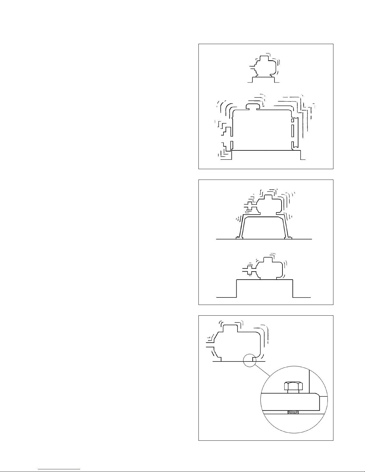
A large diesel engine vibrates more than a small electric motor - the forces involved are very different.
More force is needed to vibrate a machine on a stiff
concrete foundation than it takes to shake the same
machine on a flexible metal frame. The machine structures are different and so are their normal vibration
levels.
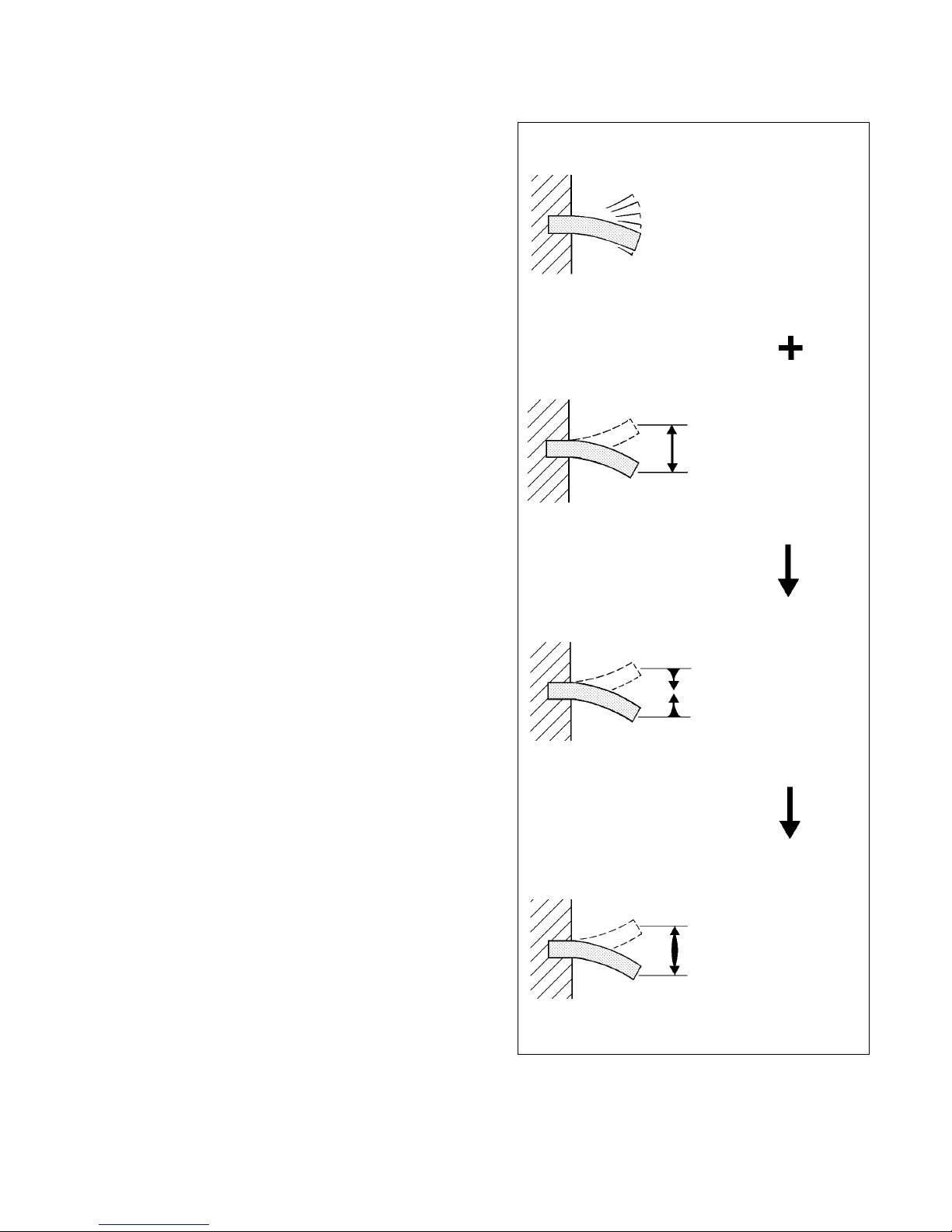
Due to changes in the operating conditions and the
mechanical state of machines, vibration levels are subject to gradual or sudden changes. Loose fixing bolts
or excessive bearing play will make the structure less
rigid - vibration will increase. A growing soot layer on
the impeller blades of an exhaust fan adds to the out
of balance forces. Vibration will increase above the
normal level and show that the machine is getting
worse. Usually the deterioration accelerates: heavier
vibration will further weaken the structure which in
turn will raise the vibration level.
Page 5
4
Technical data are subject to change without notice.
ISO 9001 certified. © Copyright SPM 2003-10. 71679.Z
SPM Instrument AB • Box 4 • SE-645 21 Strängnäs • Sweden
Tel +46 152 22500 • Fax +46 152 15075 • info@spminstrument.se • www.spminstrument.com
Measurement
If a fan is out of balance, it will shake at its speed of
rotation, i.e. move backwards and forwards once per
revolution. The number of vibrations per time unit is
the vibration frequency, measured in Hz (Hertz =
cycles per second).
The rotational speed of any piece of plant is known as
its fundamental frequency. For a fan with a speed of
1 500 r.p.m. the fundamental frequency is 25 Hz (1
500 r.p.m. ÷ 60).
In practice, machine vibration usually consists of many
different frequency components. For a general assessment of machine condition one uses wide fre-
quency band measurements, that is all vibrations
within a large frequency range are measured simultaneously.
Cyclic movement can be measured and described in
three different ways, as
· displacement
· acceleration
· velocity
Displacement means the actual distance the object
moves, measured either from its rest position in one
direction (peak) or as the total movement in both
directions (peak to peak). Displacement is usually measured in mils.
A part that is moving from rest, speeding up, slowing
down and stopping twice per cycle is obviously accelerating and decelerating continuously. Acceleration is
measured in g (1 g = 32.17 ft/sec2).
The third measuring parameter is the speed at which
the object moves, the vibration velocity. Velocity is
expressed in in/sec.
Both acceleration and speed are constantly changing.
One can measure a peak value of either, but a mean
value often gives a better indication of the forces
involved in the movement. Most instruments measure
the RMS value (root mean square value) of the movement and use a scaling factor to indicate the peak
levels if they are given at all.
Frequency
Hz
Displacement
mil
Acceleration
g
Velocity
in/s
Page 6
5
Technical data are subject to change without notice.
ISO 9001 certified. © Copyright SPM 2003-10. 71679.Z
SPM Instrument AB • Box 4 • SE-645 21 Strängnäs • Sweden
Tel +46 152 22500 • Fax +46 152 15075 • info@spminstrument.se • www.spminstrument.com
Measure Acceleration - Display Velocity
All three vibration parameters - displacement, acceleration, velocity - are mathematically related. One
can, for example, place an accelerometer on a vibrating surface and convert its signal, via integrating circuitry in the measuring instrument, into a reading of
vibration velocity or displacement.
The choice of displayed parameter (the instrument
reading) and measured parameter (the transducer type
used) depends on the problem to be solved and on
the cost, the complexity and the reliability of the
measuring equipment.
Experience has shown, that the RMS level of vibration
velocity, measured over a frequency range of 10 to
1000 Hz, is most useful for general assessment of
machine condition. The technical term used is vibra-
tion severity, defined as above and displayed in in/s
RMS on the instrument. Vibration severity is directly
related to the energy level of machine vibration, and
thus a good indicator of the destructive forces acting
on the machine.
There are transducers which measure velocity directly,
i.e. seismic probes with either moving coils or moving
magnets. These transducers are normally bulky, easily
damaged and expensive to manufacture. They are
therefore gradually being replaced by accelerometers.
An accelerometer is basically a piezo electric crystal (a
crystal that develops an electric charge when it is
compressed or stretched) with a small reference mass
attached. As the transducer is moved back and forth,
the reference mass compresses and stretches the crystal and the transducer gives an output directly related
to acceleration.
Piezo electric accelerometers are small, very robust
and relatively cheap to produce. They can work over a
very large frequency range. They can be mounted on
machines, held by hand against a vibrating surface or
be temporarily attached by wax or magnets. That is
why most practical measuring systems now use an
accelerometer as the transducer and an integrator
within the instrument to give a display in terms of
velocity.
in/s
RMS
Piezo electric
crystal
Housing
Mass
Base
Output
Integrator
Accelerometer
Piezo electric accelerometer
Page 7

6
Technical data are subject to change without notice.
ISO 9001 certified. © Copyright SPM 2003-10. 71679.Z
SPM Instrument AB • Box 4 • SE-645 21 Strängnäs • Sweden
Tel +46 152 22500 • Fax +46 152 15075 • info@spminstrument.se • www.spminstrument.com
Machine Classes
To assess machine condition, the vibration severity
measured on a specific piece of plant has to be compared with a representative norm value.
The international standards group industrial machinery into six different vibration classes , depending on
·machine size and function
· stiffness of foundation
For each class, the standards give vibration severity
levels in four bands, ranging from very good condition through average and poor to bad. Provided that
the correct class is chosen, the instrument reading
can be directly related to machine condition.
Most industrial plants belong to vibration classes II, III
and IV.
Class I refers to independent parts of machines, for
example electric motors up to 15 kW.
Classes V and VI are used for heavy reciprocating
prime movers and machines which are intended to
vibrate - for example vibrating screens (see Appendix
page 15 for precise definitions).
Motor power and types (electric, turbine, diesel), machine size and foundation stiffness (concrete base,
metal frame, etc.) will give a first indication of machine class. For example, most smaller process pumps
on a chemical plant would be Class II. A 100 kW
ventilation fan on a concrete base would be Class III.
However, the same fan fastened to the less rigid
metal deck of a ship could be considered as Class IV.
Classification of machinery is largely a matter of experience because the definitions provided by the standards are deliberately loose. Manufacturers should be
able to specify acceptable vibration levels for their
equipment, and their information can be used as a
reference.
Similarly, if it is reasonably sure that a machine is in
good condition, the actual vibration reading can be
used as a starting point for the assessment of future
changes.
in/s RMS
Limits Class Class Class Class
II Medium size machines
without special foundations
III Large machines on rigid
foundations
IV Large machines on soft
foundations
Page 8

7
Technical data are subject to change without notice.
ISO 9001 certified. © Copyright SPM 2003-10. 71679.Z
SPM Instrument AB • Box 4 • SE-645 21 Strängnäs • Sweden
Tel +46 152 22500 • Fax +46 152 15075 • info@spminstrument.se • www.spminstrument.com
Measuring Points
Vibration at the measuring point should be representative of the overall vibration pattern of the machine. The forces involved are usually transmitted
through the bearings and their housings to the machine foundation. Consequently measuring points
should be located on or near the bearing housings.
Machine guards, cover panels and other parts which
are considerably less stiff than the main structure are
not suitable as measuring points.
Generally speaking, the more measuring points chosen, the easier it is to locate a specific mechanical
problem. Consider a fan, belt driven from an electric
motor. Measurements taken on the fan bearing (3)
will primarily give information on fan balance. If out of
balance is the only problem to guard against, measuring on that bearing will be sufficient. To be able to
make an adequate assessment of the mechanical state
of the whole machine, one should also measure on
the drive end bearing (2) and the motor (1).
The direction of measurement is very important. Out
of balance forces rotate with the shaft and cause
radial vibration acting in all directions within the plane
of rotation.
Axial vibration, along the line of the shaft, is normally
caused by faulty alignment, i.e. badly assembled couplings or bent shafts.
Normal practice is to take vibration readings in three
directions at each measuring point: vertical (V), horizontal (H) and axial (A). Of the two radial measurements, a reading in the vertical direction tends to give
information about structural weakness, whereas the
horizontal reading is most representative of balance
conditions.
The measuring point, meaning the exact spot on the
machine where the transducer is placed, should be
clearly marked and used each time a reading is taken.
Relatively small changes in the measuring point can
cause misleading changes in the measured value and
trend analysis difficult.
Axial vibration
Radial vibration
Page 9

8
Technical data are subject to change without notice.
ISO 9001 certified. © Copyright SPM 2003-10. 71679.Z
SPM Instrument AB • Box 4 • SE-645 21 Strängnäs • Sweden
Tel +46 152 22500 • Fax +46 152 15075 • info@spminstrument.se • www.spminstrument.com
Recording of Readings
The SPM follow-up form provides space for readings
in all three directions at up to four different points,
which should adequately cover most industrial machines. Experience will soon show which of the points
and directions provide the most useful information
for diagnosing a specific problem on any particular
piece of plant.
In the case of a furnace extract fan (example opposite), three measuring points should be sufficient. With
this type of machine, the usual problem is out of
balance caused by soot on the impeller blades. That
makes the vibrations measured in the horizontal direction at point 3 most significant. General directives
for maintenance (6) should be based on the readings
at that point.
A graph (11) is the best way to show clearly all significant changes of the vibration level. To keep the form
simple, draw only the graph for the most significant
direction (7), normally that giving the highest readings.
In the example, the extra space (17) was used for a
second graph for the important point 3, in order to
show the axial vibration trend as well.
There are no general rules about how often vibration
should be measured. The intervals between readings
- a day, a week, perhaps a whole month - depend
wholly on the individual machine, its work, its importance for the plant and on the rate of change in its
vibration level. Obviously an exhaust fan with a soot
problem will need more frequent surveillance than a
fresh air fan, but only practical experience can help to
determine the optimal number of checks per month.
If the form is to be used for machines class I, V or VI,
fill in the relevant vibration levels under (16). Note
that the condition bands (12-15) only apply if the
machine is classed correctly.
Preparation
1 Record chart number
2Machine designation, number and
location
3Machine class
4Machine sketch with numbered
measuring points
5 Vibration class and levels (cross out
figures which do not apply)
6 Directives for maintenance
7 Number of measuring point and
direction plotted on chart
8H = horizontal, V = vertical, A = axial
Measurements
9 Date of measurement
10 Measured value in three directions
11 Plotted value of main direction
Machine Condition
12 dark red – bad condition
13 pale red – just tolerable
14 pale green – acceptable
15 dark green – good condition
Chart Modification
16 Other machine classes and their
respective vibration levels:
bad
tolerable
acceptable
good
IVVI
0.43 2,80 4.33
0.28 1.77 2.80
0.18 1.10 1.77
0.11 0.71 1.10
0.07 0.43 0.71
0.04 0.28 0.43
0.03 0.18 0.28
0.02 0.11 0.18
0.01 0.07 0.11
Page 10

9
Technical data are subject to change without notice.
ISO 9001 certified. © Copyright SPM 2003-10. 71679.Z
SPM Instrument AB • Box 4 • SE-645 21 Strängnäs • Sweden
Tel +46 152 22500 • Fax +46 152 15075 • info@spminstrument.se • www.spminstrument.com
VIC-12
Page 11

10
Technical data are subject to change without notice.
ISO 9001 certified. © Copyright SPM 2003-10. 71679.Z
SPM Instrument AB • Box 4 • SE-645 21 Strängnäs • Sweden
Tel +46 152 22500 • Fax +46 152 15075 • info@spminstrument.se • www.spminstrument.com
Measuring Equipment
The SPM equipment for manual vibration monitoring
consists of:
• Vibrameter VIB-11B
•Measuring cable 46044 (46045)
• Vibration transducer TRV-23 (TRV-22)
• TRX-16, Magnetic base for TRV-22
• TRX-17, Probe for TRV-22.
Follow-up forms can be supplied in pads of 25 each
(ordering number VIC-12).
Transducer Mounting
The accuracy of vibration readings depends largely
on the connection between transducer and measuring point. Only stiff connections, by magnet, screw or
cement, will allow the transducer to accurately follow
the movements of the vibrating surface.
Magnetic Mounting
The vibration transducer is normally mounted on the
machine with the magnetic base.
Attach the transducer to a smooth, flat surface, with
the main sensitivity axis pointing in the desired measuring direction. Spot-face the contact surface if necessary. The magnetic base has a diameter of 27.5 mm.
Screw Mounting
Screw mounting is the best alternative where the
magnetic base cannot be used. Prepare threaded
mounting holes as shown in the figure.
TRV-23 has thread size UNF 1/4"-28 and TRV-22 has
M8. The transducers are delivered with three washers
for adjusting the connector angle. Each washer turns
the transducer 90°.
If the vibration transducer is to be permanently
mounted on the machine, secure the low noise coaxial
cable with a clamp close to the connector (see figure).
For installations in moist environments, use sealing
TNC cable plugs SPM 13008 to prevent cable corrosion.
TRX-17
TRX-16
TRV-22/23
VIB-11B
Cable
clamp
min. 16ø 6.9
(ø 5.5)
M8
(UNF
1/4" -28)
min. 12
max. 0.7
min. 10
Main sensitivity axis
46044
46045
ø 27
17
ø 27.5
41.5
9
ø 15
t
TRV-22: t = M8
TRV-23: t = UNF 1/4" -28
Page 12

11
Technical data are subject to change without notice.
ISO 9001 certified. © Copyright SPM 2003-10. 71679.Z
SPM Instrument AB • Box 4 • SE-645 21 Strängnäs • Sweden
Tel +46 152 22500 • Fax +46 152 15075 • info@spminstrument.se • www.spminstrument.com
Hand-held Probe
With the probe TRX-17 attached, the vibration transducer can be used as a hand-held probe. The probe
can be fastened directly to the transducer TRV-22.
Hand-held probes are widely used for quick vibration
surveys. The advantages are obvious - there is no
need to prepare measuring points. Note, however,
that the overall stiffness is poor, which can give gross
measuring errors. Using a hand-held probe requires
practice and repeatable results cannot be guaranteed.
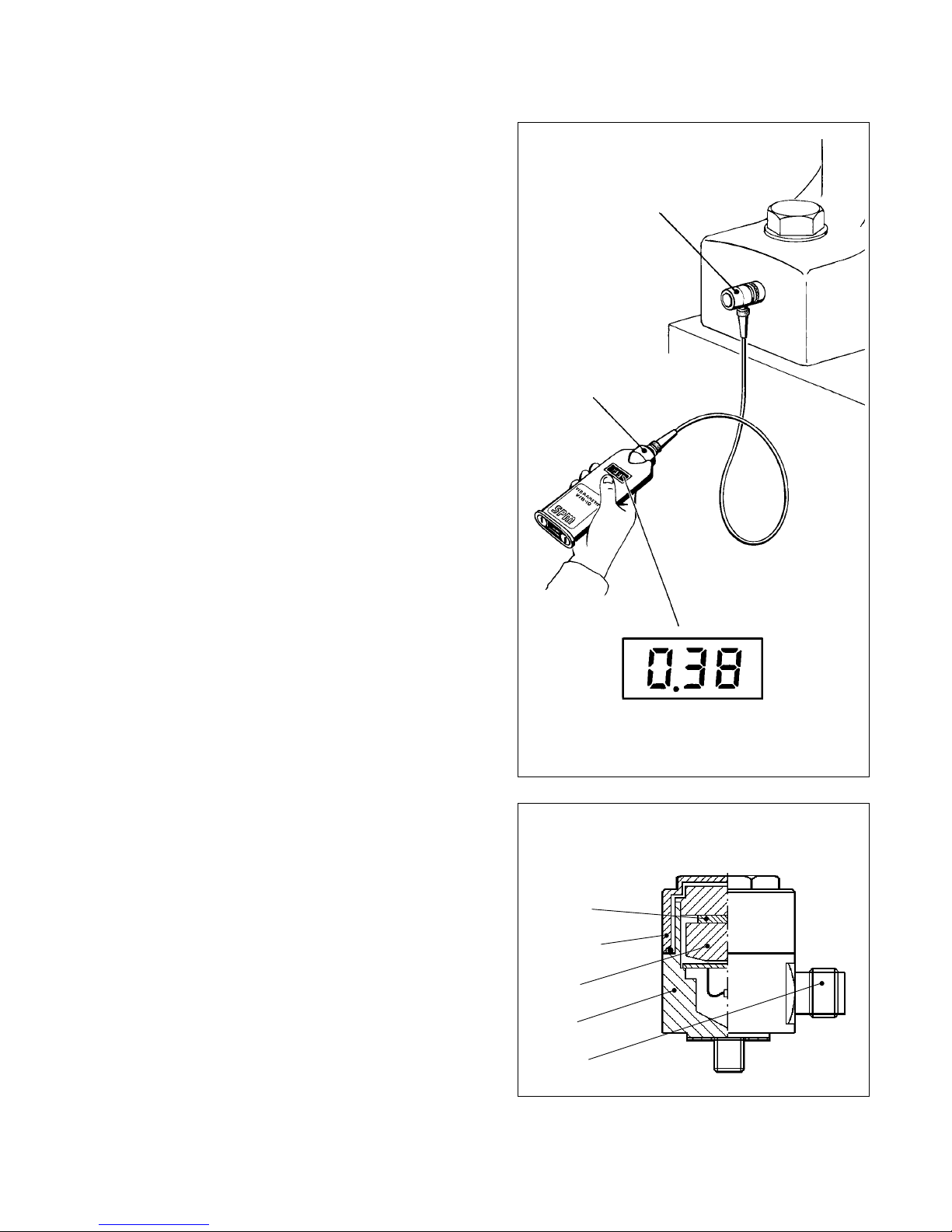
Taking Readings
Connect the transducer to Vibrameter VIB-11 with the
measuring cable. Attach the transducer to the measuring point.
Press the button below the display window and hold
it down. Wait for the readout to stabilize. Read and
record the result.
To switch off the instrument, release the button.
If the display shows "OFL", the instrument has an
overflow, caused by signals above the masuring range.
Changing Batteries
The display will show "Lob" when the battery voltage
is getting low.
Use a coin to give both locks of the battery compartments a quarter turn to the right or left. Insert new
batteries as shown on the back of the instrument.
Use only alkaline battery cells, 1.5 V, for example MN
1500 or UCAR E91. Leaking batteries can destroy the
instrument. Remove the batteries before storing the
vibrameter for long periods.
Page 13

12
Technical data are subject to change without notice.
ISO 9001 certified. © Copyright SPM 2003-10. 71679.Z
SPM Instrument AB • Box 4 • SE-645 21 Strängnäs • Sweden
Tel +46 152 22500 • Fax +46 152 15075 • info@spminstrument.se • www.spminstrument.com
Maintenance Based on Vibration Records
The purpose of regular vibration measurements is to
collect data for “condition based maintenance“, i.e.
maintenance carried out whenever condition measurements indicate a need for action.
To be able to plan ahead and work efficiently, a maintenance department needs regular and easily interpreted information on all significant changes in machine condition.
The flow chart opposite provides general rules for the
interpretation of vibration data. The diagram above
shows an example of how maintenance information
can be reduced to a few simple facts, which are passed
easily through one department to another.
Establish Norm Values
Usually, when vibration measurements start, the machine is in good condition. If its vibration class is
correctly chosen, the initial readings taken after a
running-in period should be in the “good“ or “acceptable“ range. Record these values and use them as a
standard of reference for this particular machine.
Provided the vibration level at all measuring points
remains stable, the subsequent readings are a matter
of routine. Small fluctuations of the values on the
follow-up forms are to be expected. They will hardly
show up on the graphs and the actual figures are
unimportant from a maintenance point of view.
Report Significant Changes
A one step change in the vibration level is generally
regarded as significant and should be reported. One
step is the space between two lines on the follow-up
form. For all machine classes at any level, it repre-
sents a 1.6 times increase (decrease) from the previous reading or, if the change is gradual, from the
original norm value.
For maintenance, it is a first warning that machine
condition is getting worse. At this stage, tightening a
few bolts or adjusting a belt may be sufficient to get
rid of the excess vibration and prevent further deterioration.
Each condition band consists of two steps. An increase from a starting point in the “good“ range to a
corresponding point in the next range means that
vibration has gone up 2.5 times. A large change like
that should be investigated, even though the vibration level is still “acceptable“.
Reporting changes in step is the simplest way of indicating the extent and urgency of a maintenance problem. If needed, the supporting figures are on record.
Moreover, the method is flexible. As experience increases, individual alarm levels and in-house limits can
be easily marked on the recording forms.
Basic Fault Analysis
It should be clearly understood that Vibrameter VIB11 is not intended to supply data for detailed fault
analysis. However, readings from several measuring
points in three directions can usually give a good
indication of the nature and location of the maintenance problem. Again, the flow chart may serve as a
general guide.
Notice where on the machine and in what direction
the measured value changes most. A simple report
(“motor bearing, up two steps, axial + radial“) gives a
repair crew a starting point and can save them a lot of
trouble.
Vibration
Measurement
(Shutdown)
Effect repairs
Plan major
overhaul
Inspection
minor repairs
Routine
maintenance
(lubrication, etc.)
Report dangerous increase
Report large increase
Report change
+ 4 steps
+ 3 steps
+ 2 steps
+ 1 step
Normal
Vibration severity Breakdown
Maintenance
Activities
Page 14

13
Technical data are subject to change without notice.
ISO 9001 certified. © Copyright SPM 2003-10. 71679.Z
SPM Instrument AB • Box 4 • SE-645 21 Strängnäs • Sweden
Tel +46 152 22500 • Fax +46 152 15075 • info@spminstrument.se • www.spminstrument.com
Fault Analysis Chart
Vibration up 2 steps from original or good level:
Plan to maintain, measure more frequently.
Vibration up 3 steps:
Inspect and maintain as soon as possible,
measure daily.
Vibration up 4 steps or more:
Shut down immediately and investigate.
Where
?
Part of
machine
All over
machine
Axial
+ radial
How
much
?
> 1 step
Record results.
Measure again
according to
schedule.
No
change
Increase
Treat large unexplained decrease like large
increase. Investigate soonest.
Recent maintenance, machine off load or stopped.
Measuring fault.
Something broken, loose, or missing.
Change
?
Measure Vibration Severity
Plan to maintain
when vibration
increases 2 steps
above new or
good level.
Slow build-up of
dirt.
Steady wear,
corrosion.
Stretched or
slipping belts.
Direc-
tion
?
Slack mounting bolts,
loose frame parts,
etc.
Coupling wearing or
stiffening.
Gear tooth wear.
Mainly
radial
< 1 step
Time Schedule Machine Class Measuring Point
Decrease
Radial and axial:
Slack or sheared
mounting bolts.
Damaged machine
feet, bent or
damaged subframes
or supports.
Faulty alignment,
bent or cracked
shaft.
Gear tooth damage.
One step on the chart below (any class at any
level) represents a 1.6 times increase from
previous value.
Each condition band (= 2 steps) represents a
2.5 times increase, i.e. a significant change in
vibration severity.
3 steps up is a fourfold increase, an alarming
change demanding immediate action.
Class Class Class Class Class Class
RMS
mm/s
Limits
1 step
Mainly radial: Failed fan blades,
loss of balance weights,
shedding of dirt. Oil film
hysteresis whirls, excessive
bearing play.
Radial and axial: Changes in
foundation or support structure
causing serious misalignment or
looseness. Bent or fractured
shafts. Critical speed and other
resonances.
Small machines: Possibly
transmitted vibration from
larger machines.
Page 15

14
Technical data are subject to change without notice.
ISO 9001 certified. © Copyright SPM 2003-10. 71679.Z
SPM Instrument AB • Box 4 • SE-645 21 Strängnäs • Sweden
Tel +46 152 22500 • Fax +46 152 15075 • info@spminstrument.se • www.spminstrument.com
Technical Specifications
TRV-22
TRV-23
TRX-16
81030
81031
81057
81027
46044
46045
TRX-17
VIC-11
VIC-12
VIB-11B
Tools
81027 Holder for counterbore
81057 Counterbore, diam. 20 mm
81030 Pilot, UNF 1/4" (TRV-23)
81031 Pilot, M8 (TRV-22)
Literature
70977 B
Balancing with VIB-10/VIB-11
Vibrameter VIB-11B
Measuring range 0.01 to 3.93 in/s RMS,
10 to 1000 Hz
Resolution 0.01 in/s (0.1 mm/s)
Accuracy 2% ± 0.02 in/s (2% ± 0.2 mm/s)
Power supply Four 1.5 V alkaline cells
(e.g. MN 1500 or UCAR E91)
Temperature range 32 to 131 °F (0 to +55 °C)
Display 3 digits, red LED
Switch-off Automatic
Protective cover Polyurethane
Dimensions 8.3" x 2.9" x 1.2"
(210 x 75 x 30 mm)
Weight 14 oz (410 grams) incl. batteries
Connector type TNC
Vibration Transducer TRV-22/23
Nominal sensitivity, main axis 10 pC/m/s
2
(7-12 pC/m/s2 )
Transverse sensitivity max. 10%
Typical base strain sensitivity 0.01 m/s2/µ
Linear frequency range 0 to 5000 Hz
Max. peak acceleration 600 m/s
2
Temperature range -30° C to +150° C
(-22° F to +302° F)
Typical temperature drift 0.25% / °C
Casing Stainless, acid proof,
steel, AISI 316, sealed
Dimensions diam. 27.5 x 45 mm
Weight 171 grams (6 oz)
Connector type TNC
Torque limit 10 Nm (7.4 lbf/ ft)
Part Numbers
VIB-11B Vibrameter in/s, incl.battery cells
TRV-22 Vibration transducer, M8
TRV-23 Vibration transducer, UNF 1/4"-28
TRX-16 Magnetic base for transducer TRV-22
TRX-17 Probe for transducer TRV-22
46044 Measuring cable with connectors, 1.5 m
46045 Measuring cable with sealing TNC plug,
1.5 m
VIC-12 Follow-up forms in/s, pad of 25
VIC-13 Follow-up forms, balancing, pad of 25
Page 16

15
Technical data are subject to change without notice.
ISO 9001 certified. © Copyright SPM 2003-10. 71679.Z
SPM Instrument AB • Box 4 • SE-645 21 Strängnäs • Sweden
Tel +46 152 22500 • Fax +46 152 15075 • info@spminstrument.se • www.spminstrument.com
Definition of Machine Classes According to ISO 2372
The following text is a quotation from ISO 2372 (1974, E, page 6, Annex A). This ISO Recommendation has also
been published as British Standard (BS 4675, part I). A similar vibration classification of industrial machinery can
be found in VDI 2056.
In order to show how the recommended method of
classification may be applied, examples of specific
classes of machines are given below. It should be emphasized, however, that they are simply examples
and it is recognized that other classifications are possible and may be substituted in accordance with the
circum-stances concerned. As and when circumstances
permit, recommendations for acceptable levels of vibration severity for particular types of machines will
be prepared. At present, experience suggests that
the following classes are appropriate for most applications.
Class I
Individual parts of engines and machines, integrally
connected with the complete machine in its normal
operating condition. (Production electrical motors of
up to 15 kW are typical examples of machines in this
category.)
Class II
Medium-sized machines, (typically electrical motors
with 15 to 75 kW output) without special foundations,
rigidly mounted engines or machines (up to 300 kW)
on special foundations.
Class III
Large prime movers and other large machines with
rotating masses on rigid and heavy foundations which
are relatively stiff in the direction of vibration measurement.
Class IV
Large prime movers and other large machines with
rotating masses on foundations which are relatively
soft in the direction of vibration measurement (for
example turbogenerator sets, especially those with
lightweight substructures).
Class V
Machines and mechanical drive systems with unbalanceable inertia effects (due to reciprocating parts),
mounted on foundations which are relatively stiff in
the direction of vibration measurement.
Class VI
Machines and mechanical drive systems with unbalanceable inertia effects (due to reciprocating parts),
mounted on foundations which are relatively soft in
the direction of vibration measurements; machines
with rotating slackcoupled masses such as beater
shafts in grinding mills; machines, like centrifugal machines, with varying unbalances capable of operating
as selfcontained units without connecting components;
vibrating screens, dynamic fatigue-testing machines
and vibration exciters used in processing plants.
Page 17

RETURN TO VALIDATE WARRANTY
CUSTOMER COPY
71409 B
SERIAL NO. ______________________
PRODUCT _____________________________________ VERSION NO. ___________________
PURCHASE DATE ________________________________________________________________
COMPANY ______________________________________________________________________
ADDRESS _______________________________________________________________________
CITY __________________________________________ POSTAL CODE ___________________
COUNTRY _____________________________________ PHONE _________________________
USER NAME(S)_________________________________ FAX _____________________________
AUTHORIZED DISTRIBUTOR ______________________________________________________
CUSTOMER NO. _________________
SERIAL NO. ______________________
PRODUCT _____________________________________ VERSION NO. ___________________
PURCHASE DATE ______________________________ CHECKED BY ____________________
COMPANY ______________________________________________________________________
ADDRESS _______________________________________________________________________
CITY __________________________________________ POSTAL CODE ___________________
COUNTRY _____________________________________ PHONE _________________________
USER NAME(S)_________________________________ FAX _____________________________
AUTHORIZED DISTRIBUTOR ______________________________________________________
CUSTOMER NO. _________________
REGISTERED LIMITED WARRANTY
✂
PLACE
STAMP
HERE
SPM Instrument AB
Box 4
S-645 21 STRÄNGNÄS
Sweden
One (1) year limited warranty from date of purchase against defects in work-
manship or materials. Warranty is void if instrument is altered or repaired by
unauthorized service center. Warranty does not apply on any instrument
subjected to misuse or damaged by leaking batteries. Warranty is for instru-
ment only and does not cover batteries or cables. SPM reserves the right to
determine disposition as to repair or replacement of goods.
Warranty form MUST be completed and returned to SPM Instrument to vali-
date warranty.
Should the instrument require any service whether under warranty or not, you
should contact SPM Instrument or your local distributor for instructions
before returning the goods.
SPM Instrument AB
Box 4
S-645 21 STRÄNGNÄS
Sweden
SPM Instrument AB
Box 504
SE-645 25 STRÄNGNÄS
Sweden
SPM Instrument AB
Box 504
SE-645 25 STRÄNGNÄS
Sweden
 Loading...