


Ausgabedatum: Juni 2013 Revision: 7 Seite : 1/76
GRANITAMASCHINE
SLUSH MACHINE
APPAREIL À GRANITÉS
IPro
Slusher ECO
GEBRAUCHS- UND WARTUNGSANLEITUNG
OPERATOR’S MANUAL
NOTICE D'UTILISATION ET D'ENTRETIEN
DEUTSCH SEITE 2
ENGLISH PAGE 25
FRANÇAIS PAGE 49
Ausgabedatum: Juni 2013 Revision: 7 Seite : 2/76
Herausgeber der Veröffentlichung:
SPM DRINK SYSTEMS S.p.A.
Via Panaro 2
41057 Spilamberto (MO)
Ausgabe: 06/2013
Stand: 07
© 2013 – SPM Drink Systems
Alle Rechte vorbehalten. Der Nachdruck, auch auszugsweise, ohne Genehmigung seitens SPM DRINK SYSTEMS ist
untersagt.
Die Beschreibungen und Abbildungen beziehen sich auf das/die spezifische in diesem Handbuch behandelte
Gerät/Anlage. SPM DRINK SYSTEMS behält sich vor, jederzeit alle für die Serienproduktion als notwendig
erachteten Änderungen vorzunehmen.
Die vorliegende Anleitung:
ist wesentlicher Bestandteil der Lieferung und muss in Entsprechung der grundlegenden
Sicherheitsvorschriften vor dem Gebrauch aufmerksam durchgelesen werden;
wurde laut Bestimmungen der Maschinenrichtlinie 2006/42/EG ausgearbeitet und enthält die
erforderlichen technischen Informationen für die korrekte und gefahrlose Ausführung aller Verfahren;
muss sorgfältig in einem wasser- und staubdichten transparenten Umschlag aufbewahrt werden und das
Gerät während seiner gesamten Nutzzeit, auch im Fall eines Besitzerwechsels, immer begleiten. Bei Verlust
oder Beschädigung des Handbuchs können Sie unter Angabe der Daten auf dem Typenschild bei SPM
DRINK SYSTEMS ein Ersatzexemplar anfordern.
SPM DRINK SYSTEMS übernimmt keine Verantwortung für einen unsachgemäßen Gebrauch des/r Geräts/Anlage
bzw. für Schäden, die durch eine bestimmungsfremde, nicht in dieser Anleitung vorgesehene Nutzung entstehen
sollten.
Sehr geehrte Kundin, sehr geehrter Kunde,
wir beglückwünschen Sie zur Wahl eines
Qualitätserzeugnisses und sind sicher, dass
es Ihre Erwartungen erfüllen wird.
Wir danken Ihnen, uns den Vorzug gegeben
zu haben und bitten Sie, die vorliegende
Gebrauchs- und Wartungsanleitung
aufmerksam durchzulesen.

Ausgabedatum: Juni 2013 Revision: 7 Seite : 3/76
INHALT
1. WICHTIGE ANWEISUNGEN UND
HINWEISE ..................................................4
2. AUSSTATTUNG DES GERÄTES ...............4
3. HINWEISE ZUM TRANSPORT ..................4
4. HINWEISE ZUM
ANHEBEN ..................................................4
5. TECHNISCHE SPEZIFIKATIONEN ...........5
6. AUFSTELLUNG ...........................................6
7. ELEKTRISCHER
ANSCHLUSS ..............................................7
8. INBETRIEBNAHME ....................................8
9. ELEKTRONISCHE AUSFÜHRUNG ERKLÄRUNG DER SCHALTER UND
IHRES GEBRAUCHS .................................9
Manueller Betrieb ................................................9
Automatikbetrieb ...............................................10
Programmierung ................................................10
10. MECHANISCHE AUSFÜHRUNG ERKLÄRUNG DER SCHALTER UND
IHRES GEBRAUCHS ...............................14
11. GEBRAUCH................................................15
12. TÄGLICHE REINIGUNG UND
DESINFEKTION .......................................16
13. AUSSERGEWÖHNLICHE WARTUNG ...21
Reinigung des Kondensatorfilters ......................21
Überprüfung und Ersatz der Dichtungen ...........22
Winterlagerung ..................................................22
14. HAFTUNGSAUSSCHLUSS .......................22
15. FEHLERSUCHE UND ABHILFE ..............23

Ausgabedatum: Juni 2013 Revision: 7 Seite : 4/76
1. WICHTIGE ANWEISUNGEN UND
HINWEISE
Die vorliegende Gebrauchs- und Wartungsanleitung ist wesentlicher Bestandteil des
Produktes und ist als Unterlage gut aufzubewahren. Soweit nicht anders angegeben,
richtet sich das vorliegende Handbuch an
den Anwender (Personal, das das Gerät
täglich benutzt) und an das Wartungspersonal (qualifizierte Installateure und/oder
Wartungstechniker). Die nur für den Wartungstechniker bestimmten Abschnitte sind
entsprechend gekennzeichnet. Lesen Sie
die Anweisungen des vorliegenden Handbuches vor dem Gebrauch und der Installation des Gerätes aufmerksam durch.
Das Gerät ist für die Herstellung von
Granita, Sorbet und ähnlichen Produkten
aus Wasser oder Milch und Fruchtsirup
bestimmt.
Kontrollieren Sie beim Empfang des Gerätes, dass die Bestellnummer desselben der
Ihrer Bestellung entspricht, die immer auf
den Versandpapieren angegeben ist, d.h.:
- „Gerätename“ gefolgt von der fortlaufenden Seriennummer.
Dieses Gerät ist ausschließlich für den
Zweck bestimmt, für den es konzipiert
wurde. Der Hersteller haftet nicht für
eventuelle Schäden durch unsachgemäßen
Gebrauch.
Das vorliegende Gerät ist nicht für die
Benutzung durch Kinder oder Personen
vorgesehen, die in ihrer psychischen oder
motorischen Leistungsfähigkeit beeinträchtigt sind oder denen es an Erfahrung oder
Kenntnissen mangelt, es sei denn, sie
werden von einer für ihre Sicherheit
verantwortlichen Person beaufsichtigt oder
in die Benutzung des Gerätes eingewiesen.
Kinder sollten beaufsichtigt werden, um
sicherzustellen, dass sie nicht mit dem
Gerät spielen.
Das vorliegende Gerät ist nicht für den Einsatz im Freien geeignet. Das vorliegende
Gerät darf nicht an Orten installiert werden, an denen Wasserstrahlen verwendet
werden. Das vorliegende Gerät muss an
Orten installiert werden, an denen es durch
qualifiziertes Personal überwacht werden
kann.
2. AUSSTATTUNG DES GERÄTES
In der Ihnen ausgelieferten Verpackung finden
Sie:
- Die vorliegende Gebrauchs- und
Wartungsanleitung;
- die EG-Konformitätserklärung;
- 1 Tube Schmierfett (Vaseline);
- 1 Abtropfschale und 1 Saugdichtung für jeden
Behälter.
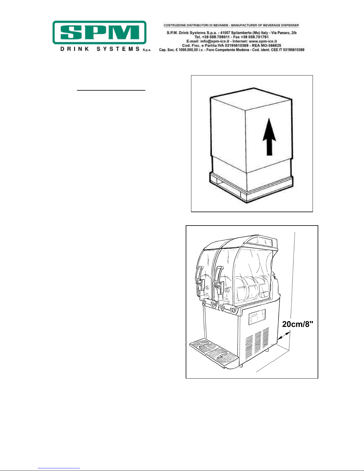
3. HINWEISE ZUM TRANSPORT
Um zu verhindern, dass das Öl aus dem
hermetischen Kompressor in den Kältekreislauf
fließt, darf das Gerät laut Angaben auf der
Verpackung nur in senkrechter Position
transportiert, gelagert und gehandhabt werden.
Falls das Gerät versehentlich oder beim
Transport waagerecht befördert wird, muss vor
der Inbetriebnahme des Gerätes etwa 3-4
Stunden gewartet werden, damit das Öl in den
Kompressor zurückfließen kann.
4. HINWEISE ZUM ANHEBEN
Jedes Gerät wird auf einer Holzpalette geliefert,
auf der es unter Verwendung gewöhnlicher
Hubmittel angehoben und transportiert werden
kann.
Achtung
Versuchen Sie nicht, das Gerät allein
anzuheben, sondern bitten Sie einen
Mitarbeiter um Hilfe.
Beim Ver- und Entladen immer vorsichtig
vorgehen, um Schäden am Gerät zu vermeiden.
Es ist möglich, das Gerät mit einem
motorisierten oder Handgabelstapler
anzuheben. Hierfür die Gabel unter dem Gerät
ansetzen.

Ausgabedatum: Juni 2013 Revision: 7 Seite : 5/76
Vermeiden Sie es,
- das Gerät zu kippen;
- das Gerät mit Seilen oder anderen Mitteln zu
ziehen;
- das Gerät mit Anschlagmitteln oder Seilen
anzuheben;
- das Gerät und seine Verpackung Vibrationen
oder Stößen auszusetzen.
Das Gerät sollte nur in trockenen Räumen mit
einer Temperatur zwischen 0°C und 40°C
gelagert werden. In der Originalverpackung
können 2 Geräte in senkrechter Stellung (siehe
Pfeile auf der Verpackung) übereinander
gestapelt werden.
5. TECHNISCHE SPEZIFIKATIONEN
Technische und elektrische Eigenschaften des
Gerätes
Alle technischen und elektrischen Kenndaten
des Gerätes sind auf dem nachfolgend
abgebildeten Typenschild im Inneren des Geräts
aufgeführt.
Das Typenschild enthält folgende Angaben:
• Modell
• Seriennummer
• Elektrische Kenndaten in Volt/Hz
• Max. Stromaufnahme in Watt
• Maximalstrom in A;
• Gewicht in kg
• Raumtemperatur des Gerätestandorts
zwischen 24 und 38°C.
Geräteabmessungen:
IPro 1
• Höhe 87 cm
• Breite 20 cm
• Tiefe 58 cm
• Gewicht 39 kg
IPro 2
• Höhe 87 cm
• Breite 40 cm
• Tiefe 58 cm
• Gewicht 60 kg
IPro 3
• Höhe 87 cm
• Breite 60 cm
• Tiefe 58 cm
• Gewicht 81 kg
Geräuschpegel
Der bewertete äquivalente Dauerschallpegel
liegt unter 70 dB.
Störungen:
Eventuelle Betriebsstörungen können in den
meisten Fällen selbst behoben werden; lesen
Sie daher aufmerksam die vorliegende Betriebsund Wartungsanleitung, bevor Sie sich an den
Hersteller wenden oder den Kundendienst rufen.
Entsorgung
Wichtig
Das gesamte Verpackungsmaterial kann
gefährlich sein und muss daher außerhalb der
Reichweite von Kindern aufbewahrt werden.
Wichtig
Belasten Sie mit der Verpackung nicht die
Umwelt. Bewahren Sie sie für späteren
Gebrauch auf (z. B. für die Lagerung in der
Wintersaison).
Das Symbol weist darauf hin, dass das
Gerät nicht als Hausmüll behandelt werden darf,
sondern nach den Bestimmungen der europäischen Richtlinie 2003/108/CE (Waste Electrical
and Electronics Equipments - WEEE) und den
betreffenden erlassenen nationalen Bestimmungen entsorgt werden muss, um möglichen
Umwelt- und Gesundheitsschäden vorzubeugen.
Wenden Sie sich für die korrekte Entsorgung
des Gerätes an den Händler, bei dem Sie das
Gerät erworben haben, oder an unseren
Kundendienst.

Ausgabedatum: Juni 2013 Revision: 7 Seite : 6/76
6. AUFSTELLUNG
NUR FÜR WARTUNGSPERSONAL
Die Installation und die späteren War-
tungsarbeiten dürfen ausschließlich von
einer im Gebrauch des Gerätes geschulten
Fachkraft unter Beachtung der einschlä-
gigen Vorschriften ausgeführt werden.
a) Nach dem Auspacken das Verpackungsmaterial für die Lagerung im Winter aufbewahren und sich vergewissern, dass das Gerät
unversehrt ist (Abb. 1).
!WICHTIG!
Das gesamte Verpackungsmaterial kann
gefährlich sein und muss daher außerhalb
der Reichweite von Kindern aufbewahrt
werden.
b) Das Gerät in einem trockenen Raum und fern
von Wärmequellen auf einer waagrechten und
soliden Unterlage aufstellen. Um eine ausreichende Belüftung des Unterbaus zu gewährleisten, muss um das Gerät ein Freiraum von mindestens 20 cm belassen werden (Abb. 2). Die
Raumtemperatur am Standort des Geräts
muss in einem Bereich zwischen 24°C und
38°C liegen.
c) Prüfen Sie, ob die Netzspannung mit den
Angaben auf dem Typenschild übereinstimmt
und die verfügbare Leistung für die Stromaufnahme des Gerätes ausreicht.
Stecken Sie den Netzstecker in eine geerdete
Steckdose und verwenden Sie keine Mehrfachsteckdosen.
LESEN SIE FÜR WEITERE
VORSICHTSMASSNAHMEN BITTE DEN
ABSCHNITT „ELEKTRISCHER ANSCHLUSS".
d) Die Installation hat gemäß den Herstelleranleitungen zu erfolgen. Eine Missachtung dieser Vorgaben kann den einwandfreien Betrieb
des Gerätes beeinträchtigen.
Wichtig
Die Erdung ist erforderlich und gesetzlich vorge-
schrieben. Ziehen Sie vor jeder Reinigung oder
außerplanmäßigen Wartung den Netzstecker,
um das Gerät vom Stromnetz zu trennen.
Gerät im Fall von Defekten oder Betriebs-
störungen ausschalten und Netzstecker ziehen.
Abb. 1
Abb. 2

Ausgabedatum: Juni 2013 Revision: 7 Seite : 7/76
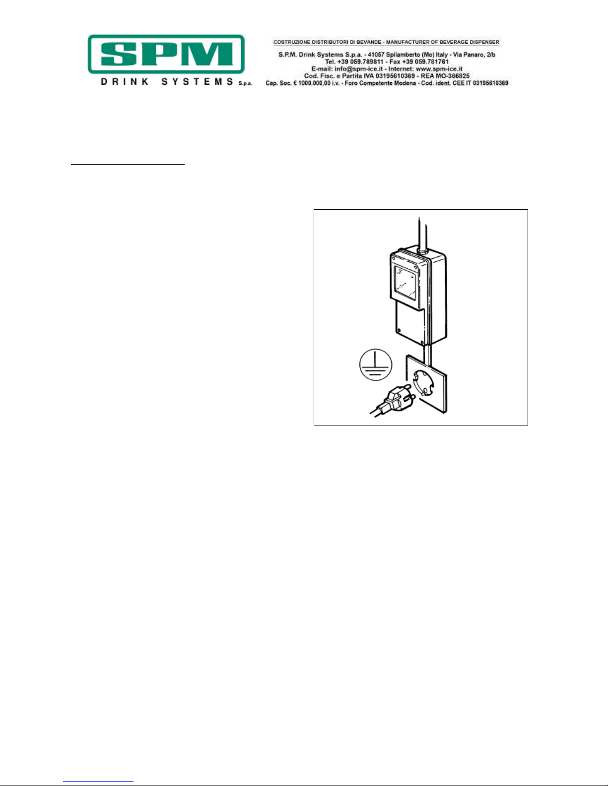
7. ELEKTRISCHER ANSCHLUSS
NUR FÜR WARTUNGSPERSONAL
Bevor Sie den Stecker in die Steckdose stecken
(siehe Beschreibung im vorangehenden
Abschnitt), ergreifen Sie zu Ihrer Sicherheit
folgende Vorsichtsmaßnahmen:
- Vergewissern Sie sich, dass die elektrische
Anlage, an die das Gerät angeschlossen werden
soll, entsprechend den Anforderungen der
einschlägigen Sicherheitsbestimmungen geerdet
ist (Abb. 3). Der Hersteller kann nicht für
Schäden aufgrund fehlender Erdung der Anlage
haftbar gemacht werden.
- Lüftungs- und Wärmeableitungsgitter nicht
zustellen. Mangelhafte Belüftung verringert
nicht nur die Leistung und beeinträchtigt den
Betrieb, sondern kann auch ernsthafte
Geräteschäden verursachen.
- Überprüfen Sie immer die elektrischen
Kenndaten auf dem Typenschild jedes einzelnen
Gerätes. Die Daten auf dem Typenschild
ersetzen in jedem Fall die Angaben des
vorliegenden Handbuches.
- Eine korrekte und sichere Installation erfordert
entsprechend den einschlägigen nationalen
Sicherheitsvorschriften einen der Steckdose
vorgeschalteten Schutzschalter mit einer
Mindestkontaktöffnung von 3 mm (Abb. 3).
- Niemals Mehrfachsteckdosen oder
Verlängerungskabel verwenden.
- Das Netzkabel darf an keiner Stelle gequetscht
oder eingeklemmt werden.
- Schalten Sie immer den Hauptschalter aus,
bevor Sie den Netzstecker vorsichtig aus der
Steckdose ziehen.
Wichtig
EIN BESCHÄDIGTES NETZKABEL MUSS AUS
SICHERHEITSGRÜNDEN DURCH DEN
HERSTELLER ODER SEINEN KUNDENDIENST
ODER AUF JEDEN FALL DURCH EINEN
TECHNIKER MIT GLEICHWERTIGER
QUALIFIKATION ERSETZT WERDEN.
Abb. 3
Ausgabedatum: Juni 2013 Revision: 7 Seite : 8/76
8. INBETRIEBNAHME
!ACHTUNG!
VOR DER INBETRIEBNAHME DES GERÄTS IST DIE
IN KAPITEL 12 BESCHRIEBENE REINIGUNG UND
DESINFEKTION AUSZUFÜHREN.
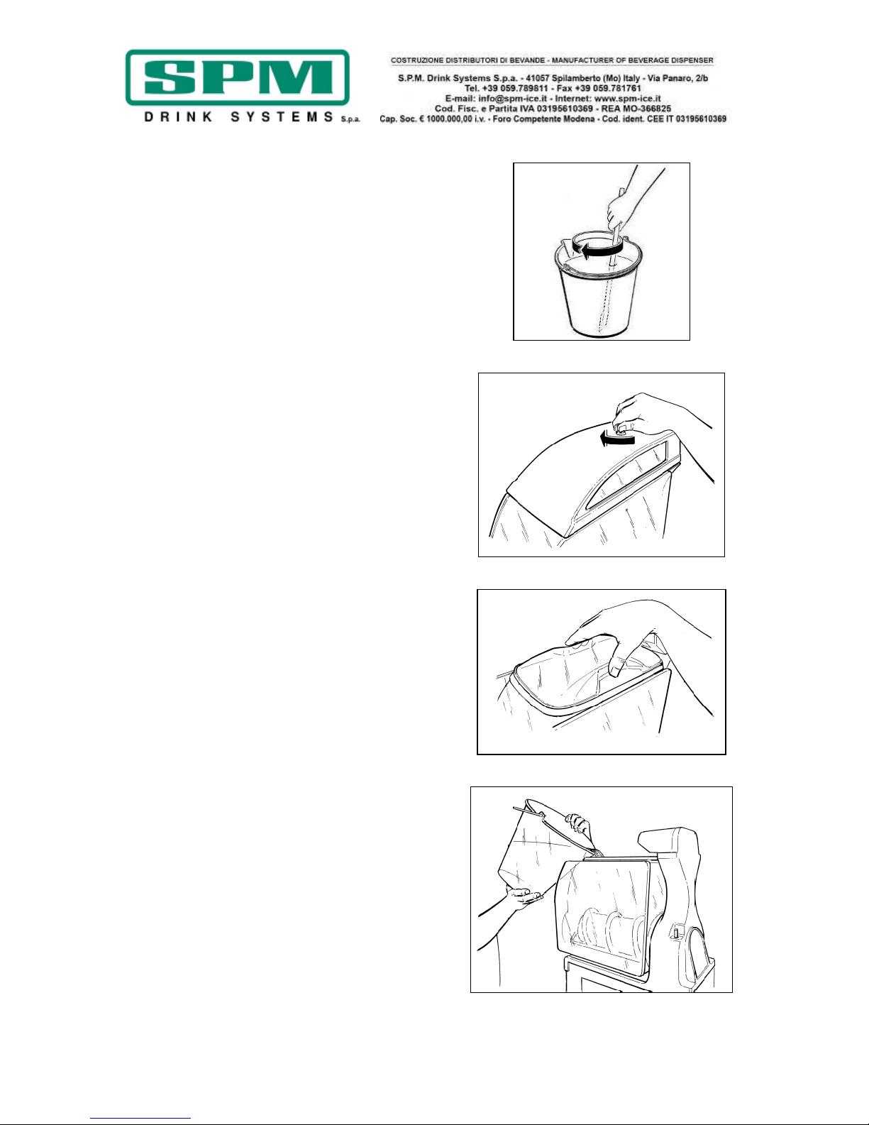
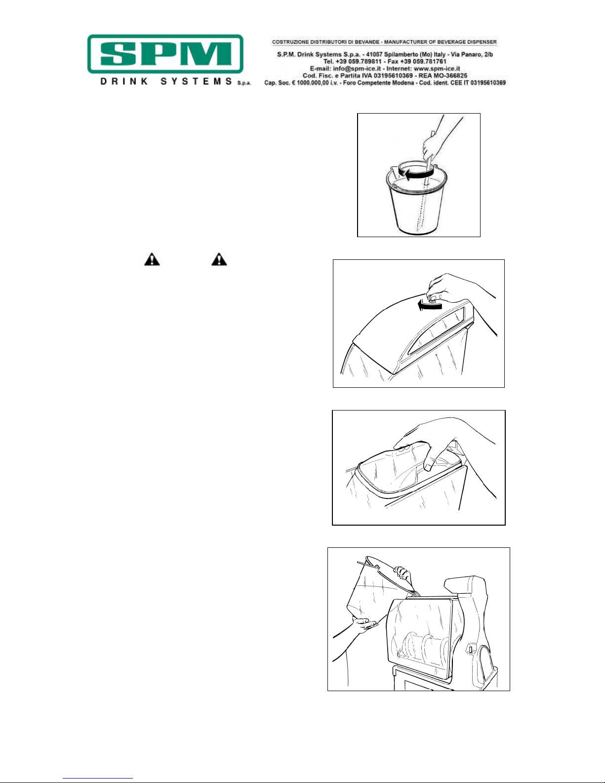
- In einem separaten Behälter den Sirup laut
Herstellerangaben mit Wasser verdünnen und
mischen (siehe Abb. 4); nie Trockenpulver,
Kristalle oder Sirupkonzentrat direkt in den
leeren Behälter geben.
!ACHTUNG!
Der Zuckergehalt muss zwischen 12.5% und
13.5% liegen; eine geringere Konzentration
kann das Mischwerk und die Motoren
schwerwiegend beschädigen.
NIEMALS NUR WASSER BENUTZEN.
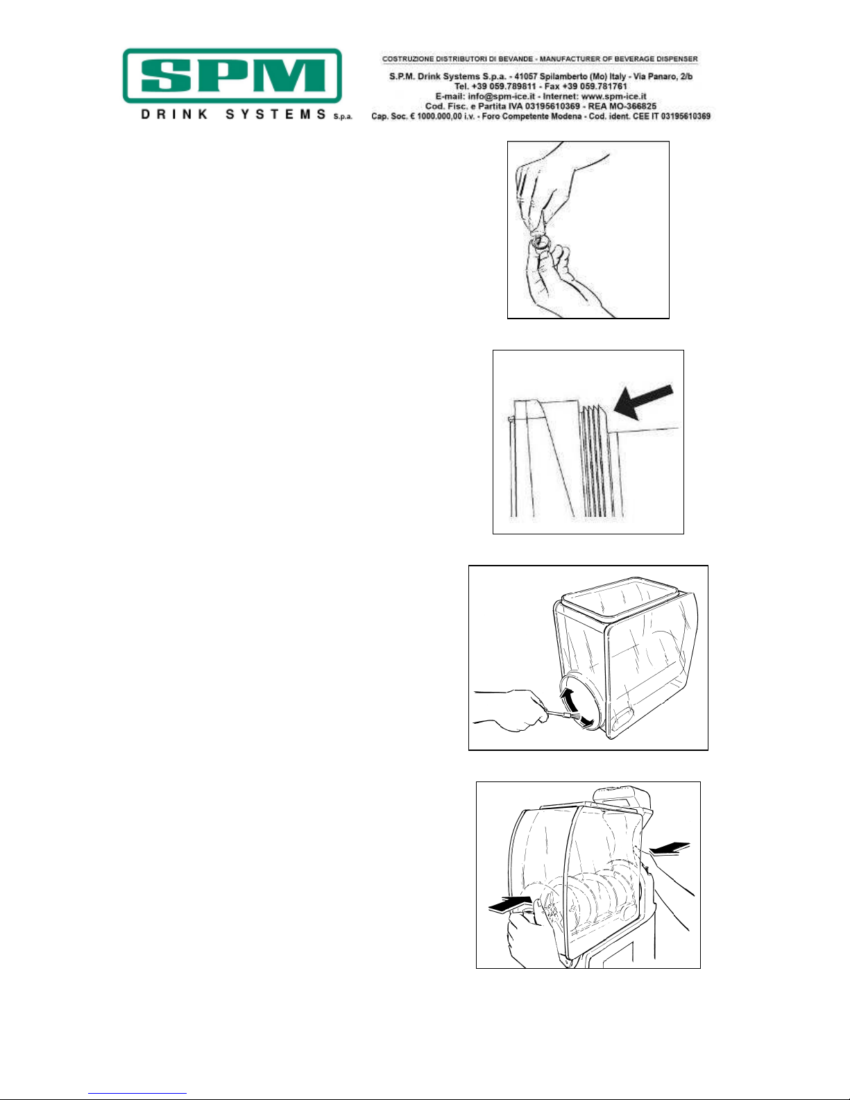
- Leuchtdeckel mit dem Spezialschlüssel
entriegeln (nach rechts drehen) und abnehmen
(Abb. 5).
- Durchsichtigen Unterdeckel abnehmen (Abb.
6).
- Gemisch in den Behälter gießen (siehe Abb.
7).
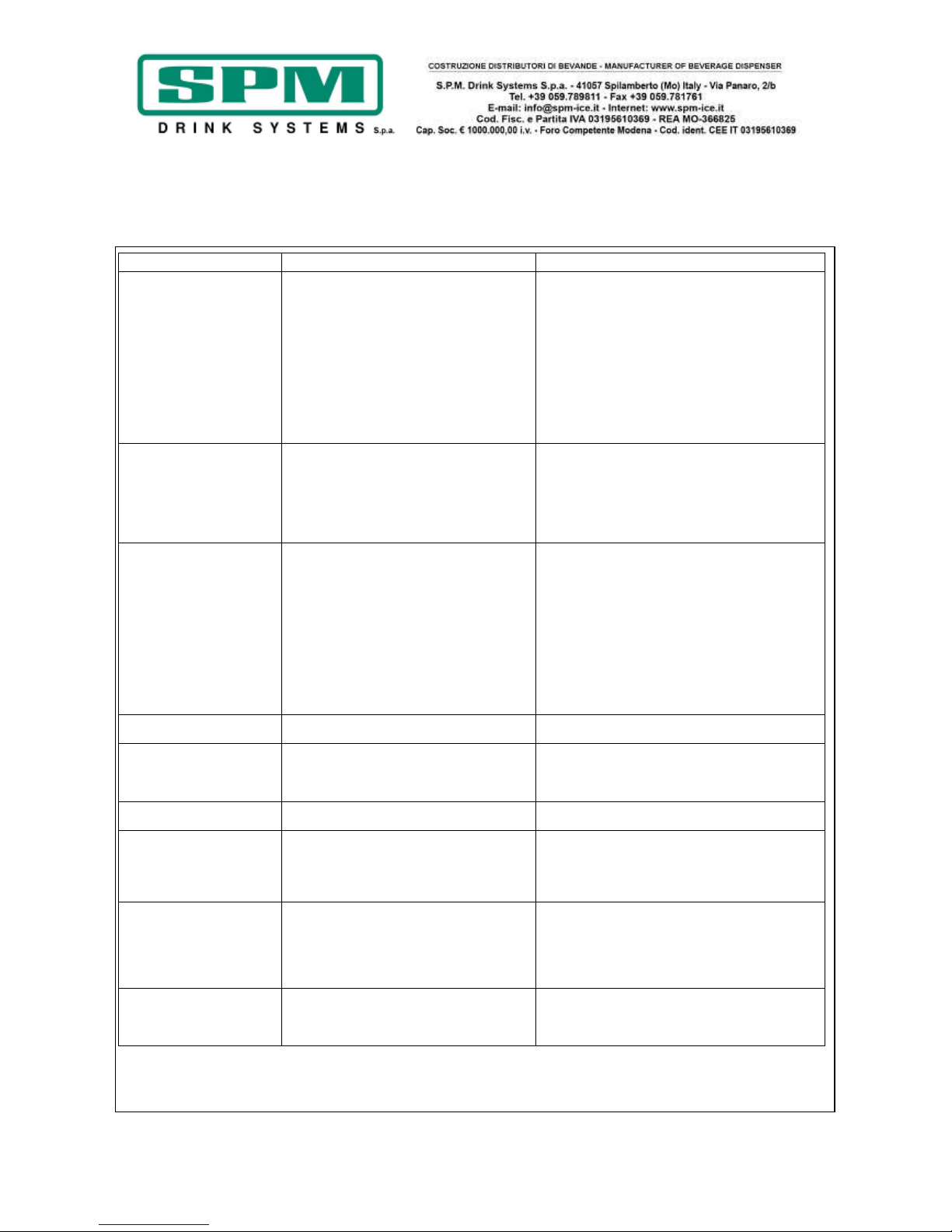
- Den Unterdeckel und danach den Leuchtdeckel
wieder aufsetzen, dabei darauf achten, dass
dieser fest auf der Sicherheitsvorrichtung
aufliegt.
- Am Ende den Leuchtdeckel mit dem
entsprechenden Schlüssel durch Drehen nach
links abschließen.
Hinweis -------------------------------------------
---IPRO ist mit einer Sicherheitsvorrichtung zum
Schutz des Benutzers ausgestattet, die beim
Anheben des Deckels den automatischen und
unmittelbaren Halt aller Bewegungsorgane
auslöst.
Falls der Deckel nicht vorschriftsmäßig
geschlossen ist, kann das Gerät nicht in
Betrieb gesetzt werden.
------------------------------------------------------
- Stecker in die Steckdose stecken und
Hauptschalter einschalten.
Abb. 4
Abb. 5
Abb. 6
Abb. 7

Ausgabedatum: Juni 2013 Revision: 7 Seite : 9/76
9. ELEKTRONISCHE AUSFÜHRUNG ERKLÄRUNG DER SCHALTER UND
IHRES GEBRAUCHS
Manueller Betrieb
Nach dem Einstecken des Steckers in die
Steckdose ist das Gerät einschaltbereit; die
Bedienblende erscheint wie in Abbildung 8
gezeigt.
Wird das kapazitive Display mit einem Finger an
der Ein-/Ausschalttaste berührt, wird das
Display eingeschaltet und erscheint wie in
Abbildung 9 gezeigt, das Gerät ist bereit für den
manuellen Betrieb.
Funktionen der einzelnen kapazitiven Tasten:
EINSCHALTEN: Zum Ein- und Ausschalten des
Geräts.
LICHT: Zum Ein- und Ausschalten der
Beleuchtung. Es blockiert bzw. entsperrt das
Bedienfeld, wenn es 5 Sekunden oder länger
gedrückt wird.
AM/PM: Wird die 12-Stunden-Anzeige
eingestellt, zeigen diese beiden Anzeiger an, in
welcher Tageshälfte man sich befindet.
WOCHENTAG: Zeigt den Wochentag an.
LEFT-CENTER-RIGHT: Über diese drei Tasten
wird die Rotation der entsprechenden Spirale
ein- und ausgeschaltet.
FREEZE: Mit dieser Taste kann das Gerät auf
Granita-Betrieb geschaltet werden.
CHILL: Mit dieser Taste kann das Gerät auf
Kühlhaltebetrieb geschaltet werden.
AUTO: Mit dieser Taste wird das Gerät auf
Automatikbetrieb entsprechend den
eingestellten Parametern geschaltet.
Abb. 8
Abb. 9
!ACHTUNG!
Die letzten drei Tasten, FREEZE, CHILL und
AUTO, können nur dann eingeschaltet
werden, wenn mindestens eine der drei
Spiralen läuft, und natürlich wird nur die
zugehörige Kühlanlage in Betrieb gesetzt.
Ausgabedatum: Juni 2013 Revision: 7 Seite : 10/76
Automatikbetrieb
Wird nach dem Einschalten die Taste AUTO
gedrückt, startet das Gerät im Automatikbetrieb
entsprechend den eingestellten Parametern; d.
h. dass das Gerät entsprechend den
programmierten Tagen und Zeiten automatisch
vom Granita- in den Kühlhaltebetrieb wechselt.
In dieser Phase sind die Tasten FREEZE und
CHILL sichtbar, aber nicht anwählbar.
!ACHTUNG!
IPRO ist mit isolierten Behältern
ausgestattet. Die Produkttemperatur wird auf
diese Weise für viele Stunden gehalten, so dass
wir empfehlen, dass die Maschine im Kühl- bzw.
Chill-Modus so lange betrieben wird, bis das
Produkt komplett geschmolzen ist.
!WARNUNG!
Wenn die Maschine mit gefüllten Behältern
über Nacht komplett ausgeschaltet wird,
dann wird sich eine solide Eisscholle auf der
Oberfläche des Produkts bilden. In diesem
Fall ist es unbedingt notwendig den Eisblock
vor dem Wiedereinschalten der Maschine
abzuschöpfen. So schützen Sie Ihre
Maschine vor Schäden am Getriebemotor
oder an den Spiralen. Bitte versuchen Sie
niemals die Eisschollen klein zu hacken.
Programmierung
Um den Programmiermodus aufzurufen, genügt
es, den Finger auf die Einschalttaste zu legen
und dort 6-7 Sekunden zu lassen, bis die
Aktivierung des Programmiermodus durch einen
Signalton angezeigt wird.
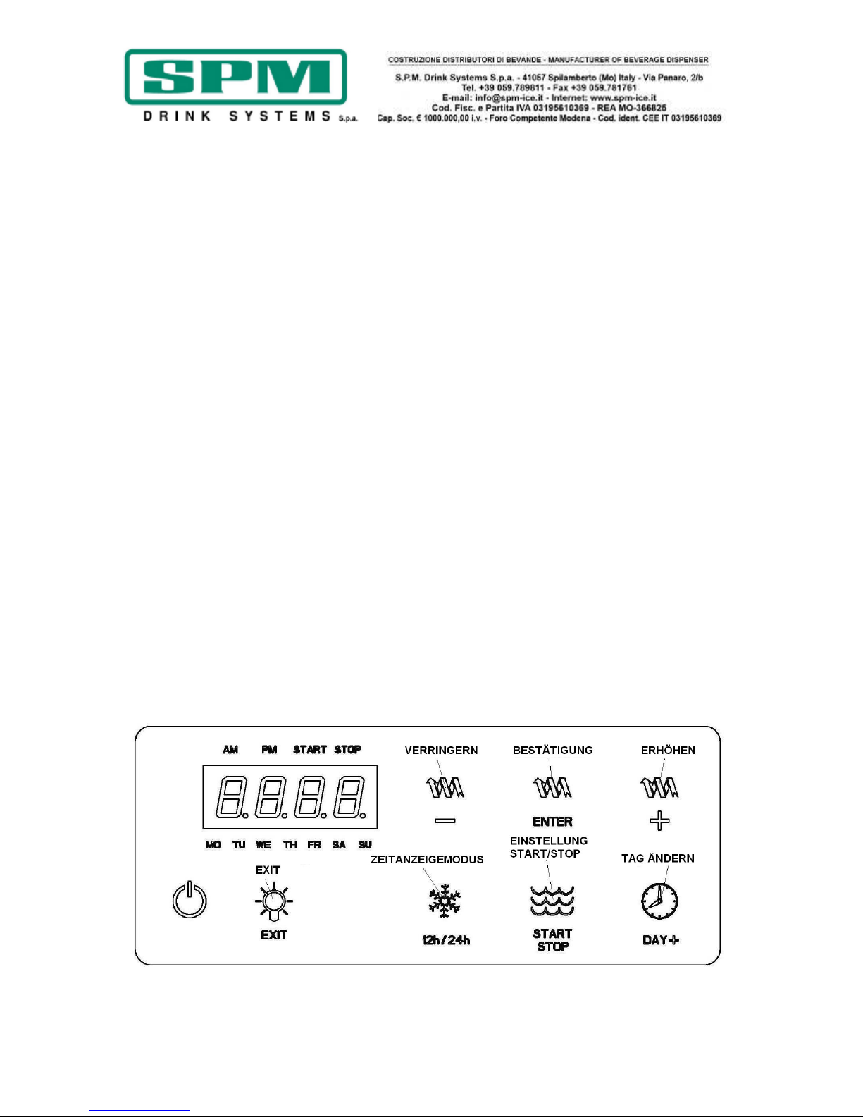
Das Display erscheint nun wie abgebildet, die
Tasten haben folgende Funktionen:
ERHÖHEN: Zum Erhöhen des Teils der Uhrzeit,
der gerade eingestellt wird.
VERRINGERN: Zum Verringern des Teils der
Uhrzeit, der gerade eingestellt wird.
BESTÄTIGUNG: Bestätigt den eingestellten Wert
und macht ihn wirksam.
TAG ÄNDERN: Zum Durchlaufen der sieben
Wochentage, um den aktuellen Tag einzustellen.
ZEITANZEIGEMODUS: Zum Einstellen der 12bzw. 24-h-Anzeige.
EINSTELLUNG START/STOP: Zum Umschalten
von der Startzeit zur Stoppzeit des Kühlbetriebs.
EXIT: Zum Beenden des Programmiermodus.

Ausgabedatum: Juni 2013 Revision: 7 Seite : 11/76
Bei Aufruf der Programmierung können folgende
Einstellungen vorgenommen werden:
• EINSTELLUNG UHRZEIT, TAG UND
ZEITANZEIGEMODUS
Sobald der Programmiermodus aufgerufen wird,
kann der aktuelle Wochentag über die Taste
TAG ÄNDERN eingestellt werden; diese Taste
muss solange gedrückt werden, bis nur der Tag
sichtbar ist, der eingestellt werden soll.
Nachdem der Tag eingestellt wurde, kann auch
eingestellt werden, ob die Uhrzeit in 12 oder 24
Stunden angezeigt werden soll; dazu kann die
gewünschte Anzeige durch Drücken der Taste
ZEITANZEIGEMODUS gewählt werden.
Nach diesen beiden Parametern kann auch die
aktuelle Uhrzeit eingestellt werden; die
Stundenanzeige blinkt auf dem Display, mit den
Tasten ERHÖHEN und VERRINGERN kann nun
die gewünschte Stunde eingestellt und mit der
Taste ENTER bestätigt werden.
Nach Bestätigung der Stunde beginnt die Zahl
der Minuten zu blinken, die ebenso mit den
Tasten + und - geändert werden kann.
Nachdem auch die Minuten bestätigt wurden,
wechselt das Gerät automatisch zur
Tagesprogrammierung des Automatikbetriebs.
• TAGESPROGRAMMIERUNG DES
AUTOMATIKBETRIEBS
Nun wird nur der erste Wochentag Montag (MO)
angezeigt sowie die Meldung START, die den
Beginn des Kühlhaltebetriebs anzeigt; dass die
Uhrzeit auf dem Display blinkt bedeutet, dass
sie mit den Tasten + und - geändert und danach
mit der Taste ENTER bestätigt werden kann.
Nach dieser Bestätigung können die Minuten
eingestellt und genauso bestätigt werden.
Nach dieser Bestätigung verschwindet die
Meldung START und es erscheint die Meldung
STOP, was bedeutet, dass das Ende des
Kühlhaltebetriebs und damit der Beginn des
Granita-Betriebs eingestellt werden kann.
Nachdem sowohl Stunden als auch Minuten
eingestellt und bestätigt wurden, wechselt die
Tagesanzeige von Montag (MO) zu Dienstag
(TU) und zeigt damit an, dass Beginn und Ende
des Kühlhaltebetriebs für Dienstag genauso
eingestellt werden können.
Auf dieselbe Weise können alle Wochentage bis
Sonntag (SU) eingestellt werden, und am Ende
erfolgt die Rückkehr zur Einstellung der
aktuellen Uhrzeit.
Durch Drücken der Taste EXIT kann nun der
Programmiermodus beendet werden.
ANMERKUNG: Nach Einstellung dieser
Zeiten hält das Gerät diese automatisch
aufrecht.
ANMERKUNG: Wenn die Taste AUTO
leuchtet, sind die Einstellungen des
Automatikbetriebs aktiv und die Tasten
FREEZE und CHILL sind gesperrt. Um diese
Betriebsart zu deaktivieren, die Taste AUTO
ausschalten.
ANMERKUNG: Die Zeitintervalle, die den
Automatikbetrieb des Geräts bestimmen,
sind für alle drei Behälter gleich.
ANMERKUNG: Mindestens eines der
Rührwerke muss in Bewegung sein, um
eine der beiden Betriebsarten „CHILL“ oder
„FREEZE“ anwählen zu können.

Ausgabedatum: Juni 2013 Revision: 7 Seite : 12/76
Alarm Filterreinigung
Der Alarm Filterreinigung wird ausgelöst, wenn
die Temperatur im Innern des Geräts zu stark
ansteigt. Wenn dies geschieht, erscheint die
Meldung „FILTER“ auf der Bedienblende, wie in
Abbildung 10 gezeigt.
Um die Ursache der Alarmauslösung zu
ermitteln und zu beseitigen, siehe folgende
Auflistung:
• Ursache A: Der Filter ist verschmutzt und
muss gereinigt werden.
Abhilfe: Filter laut Anweisungen reinigen und
wieder einbauen (Reinigung des
Kondensatorfilters Seite 24).
• Ursache B: Das Gerät ist zu nah an einer
Wand oder anderen Hindernissen aufgestellt,
die den Luftfluss behindern, wodurch es bei
zu hohen Temperaturen arbeiten muss.
Abhilfe: Gerät so umsetzen, dass der
Freiraum um das Gerät für die Belüftung
optimiert wird (siehe
Installationsanweisungen).
• Ursache C: Das Gerät ist in der Nähe einer
Wärmequelle aufgestellt, die Warmluft
erzeugt, wodurch es bei zu hohen
Temperaturen arbeiten muss (die
Installation in der Nähe von Wärmequellen
ist strikt zu vermeiden).
Abhilfe: Gerät so umsetzen, dass die Lüftung
optimiert wird.
Abb. 10

Ausgabedatum: Juni 2013 Revision: 7 Seite : 13/76
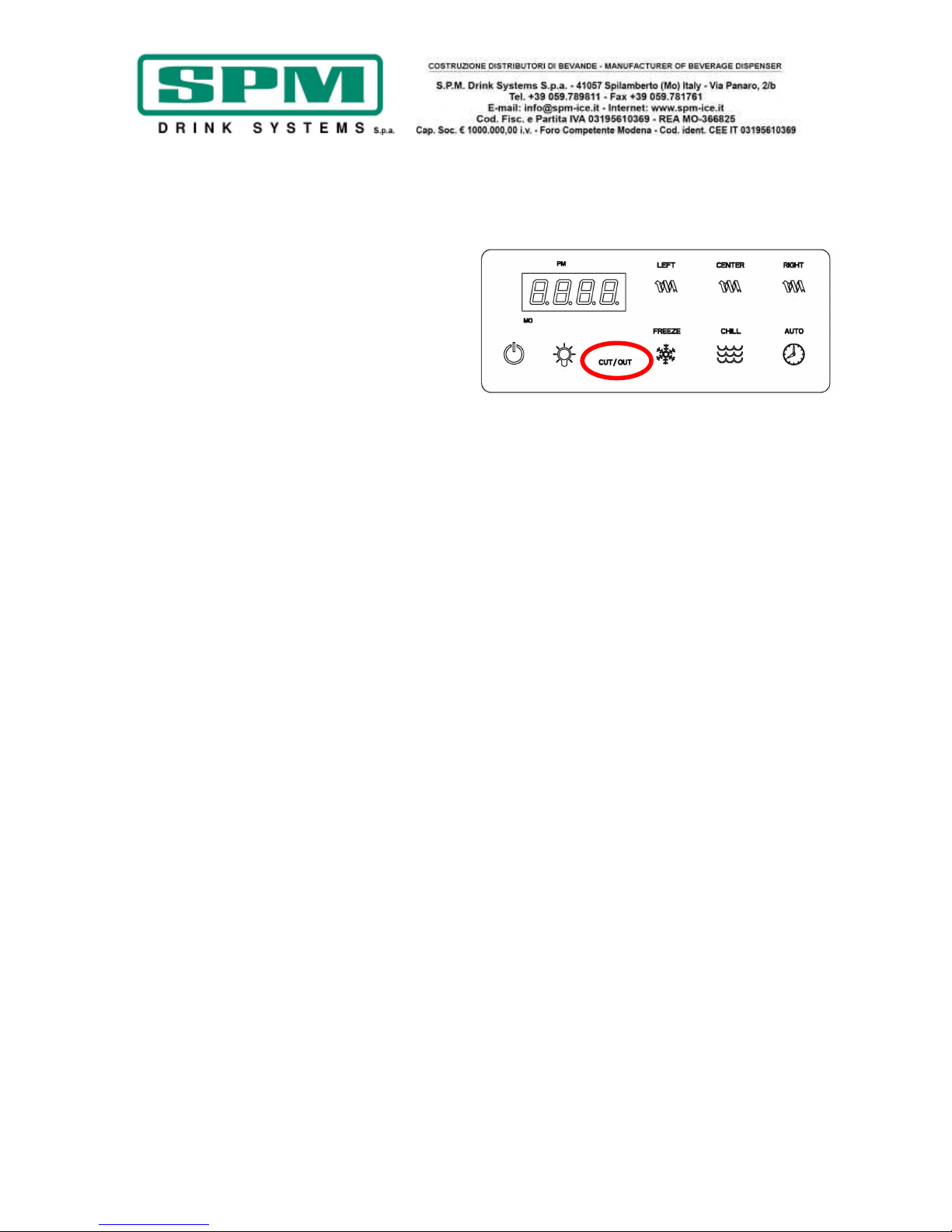
Alarm Übertemperatur
Wenn die Temperatur im Innern des Geräts den
vom Hersteller eingestellten Grenzwert erreicht,
erscheint auf dem Display die Meldung
CUT/OUT (Abb. 11) und der Betrieb der
Kühlanlage wird gesperrt, um Beschädigungen
des Kompressors zu vermeiden.
• Die Anlage geht automatisch in den Modus
„OFF“ über, der Kompressor wird
abgeschaltet und nur die Mischspiralen
bleiben in Betrieb, um die Bildung von
Eisklumpen zu vermeiden.
• Wenn dies geschieht, erscheint auf dem
Display die Meldung „CUT/OUT“ (Abb. 11).
• Wenn dies geschieht, müssen alle Schalter
ausgeschaltet und die Ursachen der Störung
und die möglichen Abhilfen ermittelt werden,
die im Abschnitt zum Alarm Filterreinigung
auf Seite 15 beschrieben sind.
Abb. 11

Ausgabedatum: Juni 2013 Revision: 7 Seite : 14/76
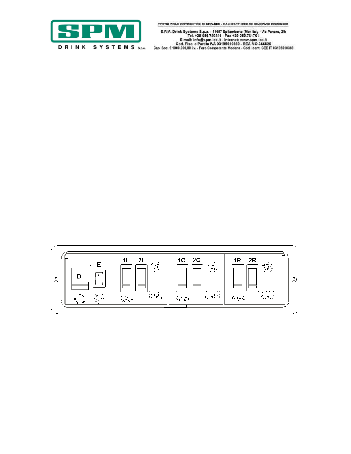
10. MECHANISCHE AUSFÜHRUNG ERKLÄRUNG DER SCHALTER UND
IHRES GEBRAUCHS
a) Hauptschalter D einschalten;
b) Jeder Behälter wird über 2 Schalter
gesteuert, die wie im Folgenden beschrieben
betätigt werden:
- Für die Herstellung von Granita oder Sorbett
mit Schalter 1 (L für den linken Behälter, C für
den mittleren und R für den rechten) das
Mischwerk in Betrieb setzen und anschließend
mit Schalter 2 (Schneeflocke) den Kältekreis im
Gefrierbetrieb zuschalten.
- Zum Einschalten der Kühlhaltung mit Schalter
1 (L für den linken Behälter, C für den mittleren
und R für den rechten) das Mischwerk in Betrieb
setzen und anschließend mit Schalter 2 (Wellen)
die Kühlanlage zuschalten, die für die
Aufrechterhaltung der Temperatur entsprechend
den Einstellungen des eingebauten Thermostats
sorgt.
c) Mit Taste E kann die LED-Beleuchtung der
Deckel ein- und ausgeschaltet werden.
!ACHTUNG!
IPRO ist mit isolierten Behältern
ausgestattet. Die Produkttemperatur wird auf
diese Weise für viele Stunden gehalten, so dass
wir empfehlen, dass die Maschine im Kühl- bzw.
Chill-Modus so lange betrieben wird, bis das
Produkt komplett geschmolzen ist.
!WARNUNG!
Wenn die Maschine mit gefüllten Behältern
über Nacht komplett ausgeschaltet wird,
dann wird sich eine solide Eisscholle auf der
Oberfläche des Produkts bilden. In diesem
Fall ist es unbedingt notwendig den Eisblock
vor dem Wiedereinschalten der Maschine
abzuschöpfen. So schützen Sie Ihre
Maschine vor Schäden am Getriebemotor
oder an den Spiralen. Bitte versuchen Sie
niemals die Eisschollen klein zu hacken.
Ausgabedatum: Juni 2013 Revision: 7 Seite : 15/76
11. GEBRAUCH
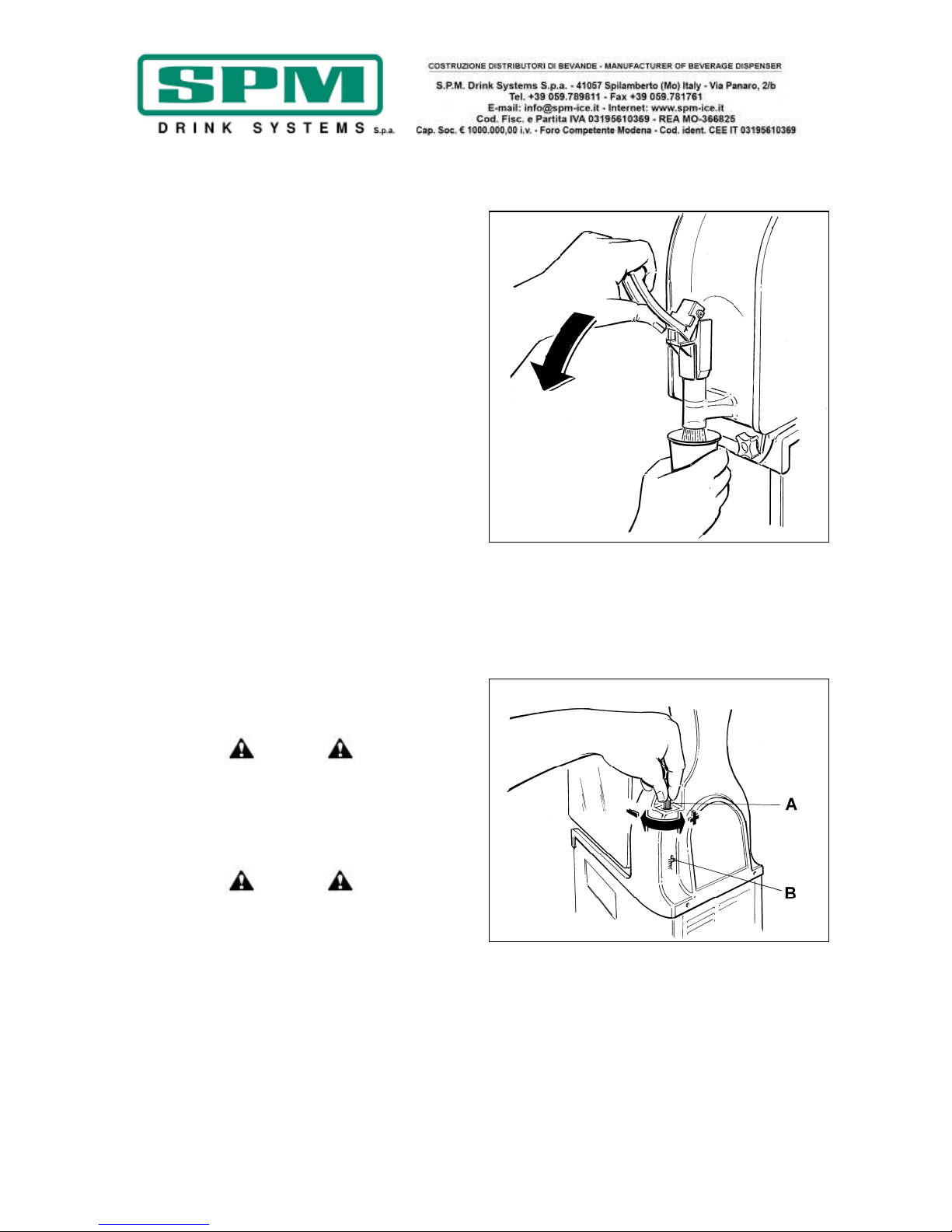
a) Für die Produktausgabe den Becher unter
den Hahn stellen und den Hebel wie in
Abbildung 12 gezeigt ziehen.
b) Einstellung der Konsistenz: zur Änderung
der Dichte des Produktes Stellknopf A an der
Geräterückseite benutzen (Abb. 13); wie an
der Skala B ersichtlich, wird bei
Rechtsdrehung das Produkt weniger
dickflüssig, bei Linksdrehung dagegen
dickflüssiger.
Achtung
Diese Vorrichtung ändert nur die Konsistenz des
auszugebenden Produktes (mehr oder weniger
dickflüssig), hat aber keinen Einfluss auf dessen
Kühltemperatur.
Achtung
Wenn der Füllstand der Granita im Behälter auf
die Höhe der Mischschnecke absinkt, muss der
Behälter aufgefüllt werden, damit das Produkt
nicht zu dickflüssig wird.
Abb. 12
Abb. 13

Ausgabedatum: Juni 2013 Revision: 7 Seite : 16/76
12. TÄGLICHE REINIGUNG UND
DESINFEKTION
Für den optimalen Betrieb und in Entsprechung
der einschlägigen Gesundheits- und
Hygienevorschriften sind eine regelmäßige und
gründliche Reinigung und Desinfektion des
Gerätes erforderlich; das mit dieser Aufgabe
beauftragte Personal ist anzuweisen, sich vor
der Arbeit die Hände und Unterarme zu waschen
und zu desinfizieren.
Nach einer längeren saisonbedingten
Nichtbenutzung muss das Gerät immer gereinigt
und desinfiziert werden.
Achtung
Spritzen Sie bei der Reinigung kein Wasser
auf die Schalter und vermeiden Sie, dass
interne elektrische Bauteile mit Wasser
und Reinigungsmitteln in Berührung
kommen. Es besteht Stromschlaggefahr!
Achtung
Um der Bakterienbildung vorzubeugen,
ausschließlich für die Desinfektion von
Kunststoff und Gummi zugelassene Mittel
verwenden. Bei Missachtung dieser
Vorschrift besteht ein Gesundheitsrisiko.
ANMERKUNG: Es obliegt dem Anwender, sich
über die einschlägigen Vorschriften zu
informieren und die Bundes-, Landes- und
örtlichen Gesetze im Hinblick auf die Häufigkeit
der Reinigung und die Lagerung der
verwendeten Produkte einzuhalten.
Die nachfolgend beschriebenen Arbeiten sind
unerlässlich, um die Bildung von Bakterien im
Gerät zu verhindern und optimale hygienische
Bedingungen des Geräts aufrecht zu erhalten.
Es wird empfohlen, die Reinigung/Desinfektion
täglich und in jedem Fall unter Einhaltung der
einschlägigen Vorschriften auszuführen.
Weder der Gerätehersteller noch der Hersteller
des verwendeten Lebensmittelkonzentrats
können für eventuelle direkte oder indirekte
Personenschäden haftbar gemacht werden, die
auf eine – auch teilweise – Nichteinhaltung der
Anweisungen des vorliegenden Handbuchs und
insbesondere der Reinigungs- und
Desinfektionsvorschriften zurückzuführen sind.

Ausgabedatum: Juni 2013 Revision: 7 Seite : 17/76
TÄGLICHE REINIGUNG UND DESINFEKTION
- Kühlanlage ausschalten (dazu entweder die
Taste mit der Schneeflocke oder die mit den
Wellen ausschalten) und das Gerät nur mit dem
Rührwerk in Betrieb etwa zehn Minuten laufen
lassen.
- Restliches Produkt aus dem Behälter
entfernen.
Achtung
Um Stromschlaggefahr und einen
versehentlichen Kontakt mit Bewegungs-
teilen während des Aus- und Wiederein-
baus der Teile zu vermeiden, kontrollieren,
dass alle Schalter auf OFF stehen und der
Netzstecker gezogen ist.
- Leuchtdeckel mit dem Spezialschlüssel
entriegeln und abnehmen.
- Behälter mit lauwarmem Wasser füllen, um die
Zuckerrückstände aufzulösen; Wasser ablassen
und dann mit dem nächsten Punkt fortfahren.
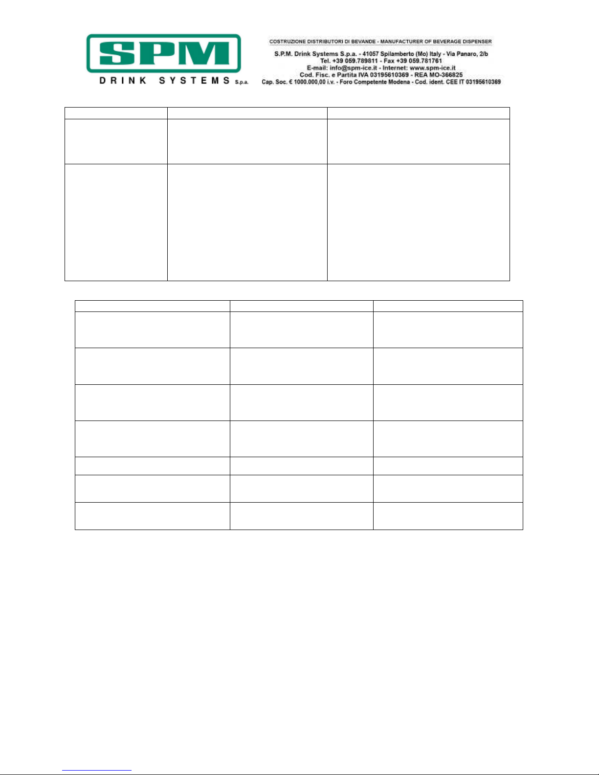
- Knöpfe abschrauben und herausziehen (siehe
Abb. 14).
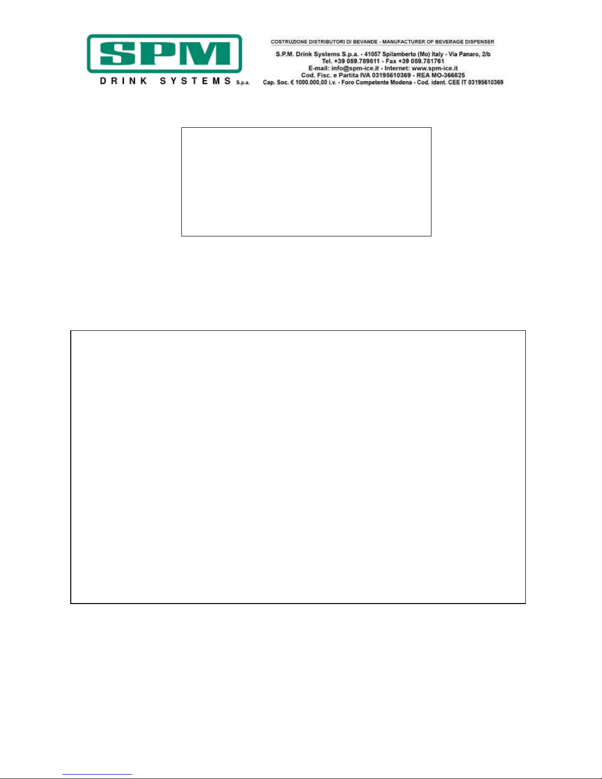
- Vorsichtig den Behälter wie in Abbildung 15
gezeigt bewegen und gleichzeitig nach außen
ziehen, um ihn aus seinem Sitz lösen zu
können.
- Gleichzeitig auf die beiden Sicherungszungen
Q drücken und Hahn I aus seiner Aufnahme
ziehen (siehe Abb. 16).
- Hahn zerlegen; dabei Gehäuse L nach unten
drücken und Hebel R aus seinem Sitz ziehen
(siehe Abb. 17).
Achtung
Um der Bakterienbildung vorzubeugen,
immer die Dichtringe herausnehmen und
diese sowie ihre Sitze reinigen; bei
Missachtung dieser Anweisung besteht ein
Gesundheitsrisiko.
Abb. 14
Abb. 15
Abb. 16
Abb. 17

Ausgabedatum: Juni 2013 Revision: 7 Seite : 18/76
- Befestigungsgriff S im Uhrzeigersinn
abschrauben (Linksgewinde), Rührwerk U und
Dichtungen X und T herausziehen (siehe Abb.
18).
Achtung
Keine scheuernden Reinigungsmittel
verwenden, die die Oberfläche der Bauteile
beschädigen können. Diese Bauteile nicht
im Geschirrspüler waschen; Bauteile wie
der Behälter oder die Spirale können dabei
beschädigt werden.
- Alle ausgebauten Bauteile gründlich mit
warmem Wasser und mildem Geschirrspülmittel
reinigen.
- Benutzen Sie ein normales Mittel, das für die
Desinfektion von Gegenständen aus Kunststoff
und Gummi geeignet ist (z. B.
Desinfektionslösung auf Chlorbasis).
- Gut abspülen und alle Teile in die
Desinfektionslösung mit den von dessen
Hersteller angegebenen Konzentrationen und
Einwirkzeiten eintauchen.
WICHTIG
Die Vorgaben des verwendeten
Desinfektionsmittels hinsichtlich
Anwendungszeiten und -art sind
gewissenhaft einzuhalten.
- Nach der vorgeschriebenen Desinfektionszeit
jedes einzelne Bauteil mit sauberem Wasser
sorgfältig abspülen und mit einem sauberen
Tuch abtrocknen.
- Verdampfer Z und Kondensatsammelfläche Y
sorgfältig abwischen, dabei alle
Produktrückstände mit einem sauberen, in
Desinfektionslösung getränkten Schwamm
entfernen (siehe Abb. 19).
- Dasselbe mit einem in sauberem Trinkwasser
getränkten Schwamm wiederholen und
sorgfältig alle Oberflächen mit einem sauberen
Tuch abtrocknen.
Abb. 18
Abb. 19
Ausgabedatum: Juni 2013 Revision: 7 Seite : 19/76
Nach der gründlichen Reinigung und
Desinfektion können die Bauteile wieder
eingebaut werden.
Die korrekte Montage des Gerätes ist sehr
wichtig, um seine Dichtheit zu gewährleisten
und Schäden zu verhindern.
Für den Zusammenbau des Gerätes ist ein
zugelassenes Schmiermittel erforderlich
(Vaseline).
Vergewissern Sie sich immer, dass alle Teile
korrekt gewaschen und desinfiziert wurden und
dass der mit der Montage beauftragte
Mitarbeiter zuvor seine Hände und Unterarme
gründlich gewaschen und desinfiziert hat.
- Rührwerk wie folgt wieder einbauen (Abb. 18):
• Als Vorbeugung gegen Abrieb und
Verschleiß die Saugdichtung X mit Vaseline
einfetten (Abb. 20).
• Dichtung T wieder einsetzen und dabei
auf die Richtung achten (Abb. 21).
• Bei der Montage der Spirale U darauf
achten, dass der Mitnehmerschaft genau in
die Führungswelle einrastet.
• Kugelgriff S linksherum einschrauben,
um alle Bauteile zu fixieren.
- Behälter in seine Aufnahme einsetzen und
kontrollieren, dass er passgenau an Dichtung T
anliegt (siehe Abb. 23). Um die Montage zu
erleichtern, empfehlen wir, die Stelle der
Behälterrückseite, die an der Dichtung anliegt,
etwas zu schmieren (Abb. 22).
- Behälter mit den Kugelgriffen befestigen, die
Knöpfe fest, aber nicht übermäßig anziehen.
WICHTIG
Befestigungsknöpfe nicht zu stark
anziehen, um Schäden am Gewinde bzw.
am Behälter zu vermeiden.
Abb. 20
Abb. 21
Abb. 22
Abb. 23

Ausgabedatum: Juni 2013 Revision: 7 Seite : 20/76
- Ausgabehahn wieder einbauen; eine dünne
Vaselineschicht auf den Hahn auftragen, um den
Einbau zu erleichtern, und ihn bis zum Anschlag
einschieben (Abb. 24).
!ACHTUNG!
Mangelhaftes Gleiten des Hahns
beeinträchtigt die Dichtheit desselben.
- Abtropfschale nach außen herausziehen (siehe
Abb. 25).
- Alle ihre Teile sorgfältig abwaschen.
- Gut abspülen und alle Teile in die
Desinfektionslösung mit den von dessen
Hersteller angegebenen Konzentrationen und
Einwirkzeiten eintauchen.
- Wieder einbauen. Dabei in umgekehrter
Reihenfolge als beim Ausbau vorgehen.
- Das Gerät ist nun bereit für eine erneute
Benutzung.
DESINFEKTION NACH LÄNGERER
NICHTBENUTZUNG
Sollte das Gerät einige Tage lang nicht benutzt
werden, nachdem es sorgfältig wie oben
beschrieben gereinigt und desinfiziert wurde,
muss es bei seiner Wiederinbetriebnahme
erneut wie im Folgenden beschrieben
desinfiziert werden.
- Zuerst den Sicherheitsdeckel, dann den
Unterdeckel abheben.
- Behälter mit Wasser füllen und ein
Desinfektionsmittel für den Lebensmittelbereich
zugeben, dabei gewissenhaft die von dessen
Hersteller angegebene Dosierung einhalten.
- Deckel wieder aufsetzen, Rührwerk laufen
lassen und den Herstellerangaben entsprechend
einwirken lassen.
Abb. 24
Abb. 25

Ausgabedatum: Juni 2013 Revision: 7 Seite : 21/76
WICHTIG
Desinfektionslösung nur so lange im
Behälter lassen wie vom Hersteller
angegeben.
- Zum Entleeren des Behälters mindestens 10mal den Hahn öffnen und schließen, um auch
den Durchflussbereich des Produkts zu
desinfizieren.
- Auf dieselbe Weise sorgfältig nachspülen,
dafür jedoch nur sauberes Trinkwasser anstelle
der Desinfektionslösung benutzen.
- Nach sorgfältiger Ausführung dieser Arbeiten
ist das Gerät gebrauchsbereit.
13. AUSSERGEWÖHNLICHE WARTUNG
Achtung
Vor allen Wartungsarbeiten müssen das
Gerät abgeschaltet und der Netzstecker
gezogen werden.
Reinigung des Kondensatorfilters
Um den optimalen Betrieb der Kälteanlage zu
gewährleisten, ist der Kondensatorfilter
sauber zu halten, indem er häufig gereinigt
wird, wie im Folgenden beschrieben:
- Gerät spannungsfrei schalten und Netzstecker
ziehen.
- Kugelgriff K abschrauben, bis Rückwand X
abgenommen werden kann (siehe Abb. 26).
- Filter des Kondensators W entfernen und
letzteren mit Wasser oder einem Staubsauger
reinigen (siehe Abb. 27).
- Filter und Rückwand wieder einbauen.
!ACHTUNG!
Wird der Kondensatorfilter nicht sauber
gehalten, kann es zu Schäden am Gerät
kommen und die Garantie kann unwirksam
werden.
Abb. 26
Abb. 27

Ausgabedatum: Juni 2013 Revision: 7 Seite : 22/76
Überprüfung und Ersatz der Dichtungen
BEHÄLTERDICHTUNG
Die Dichtung an der Behälterrückseite muss je
nach Verschleiß und Wartungs-/Schmierniveau
alle zwölf Monate ausgewechselt werden.
HAHNDICHTUNGEN (O-RINGE)
Die O-Ringe des Ausgabehahns sind bei
Anzeichen von Verschleiß auszuwechseln. Diese
Dichtungen müssen bei jedem Zusammenbau
nach der Reinigung des Geräts geschmiert und
sorgfältig auf Verschleiß geprüft werden, um
unerwünschte Undichtigkeiten zu vermeiden.
SAUGDICHTUNG
Die frontseitige Saugdichtung des Verdampfers
ist alle drei Monate auszuwechseln und auf
jeden Fall bei Anzeichen von Verschleiß. Diese
Dichtung muss bei jedem Zusammenbau nach
der Reinigung mit dem mitgelieferten
Vaselinefett eingefettet werden.
Winterlagerung
Um das Gerät bei längerer Nichtbenutzung wie
im Winter angemessen zu schützen, sind
folgende Maßnahmen zu treffen:
- Gerät von allen Energiequellen trennen.
- Alle Bauteile, die mit dem Produkt in
Berührung kommen, ausbauen, reinigen und
desinfizieren (siehe Kapitel 12).
- Auch die Außenverkleidungen reinigen.
- Gerät sorgfältig wieder zusammenbauen.
- Das vollständig montierte Gerät zum Schutz
vor Staub und anderen Schadstoffen mit seiner
Originalverpackung abdecken.
- Gerät an einem trockenen Ort lagern.
14. HAFTUNGSAUSSCHLUSS
Der Hersteller übernimmt keinerlei Haftung für
eventuelle direkte oder indirekte Personen-
/Sach- oder Tierschäden, die auf eine – auch
teilweise – Missachtung der Anweisungen des
vorliegenden Handbuchs und insbesondere der
Installations-, Gebrauchs- und
Wartungsvorschriften für das Gerät
zurückzuführen sind.
Die offizielle Sprache ist Italienisch, daher
übernimmt der Hersteller keine Verantwortung
für eventuelle Ungenauigkeiten infolge von
Druck-, Schreib- oder Übersetzungsfehlern im
vorliegenden Handbuch; er behält sich vor, alle
Änderungen vorzunehmen, die er für notwendig
und nützlich ansieht, auch im Interesse des
Benutzers, soweit diese nicht die Funktionalität
und Sicherheit beeinträchtigen.
Edition: June, 2013 Revision: 7 Pag. : 23/76
15. FEHLERSUCHE UND ABHILFE
ANMERKUNG: Die folgenden Eingriffe müssen von einem qualifizierten Techniker
ausgeführt werden.
Problem
Mögliche Ursache
Abhilfe
Das Gerät kühlt nicht
oder nur teilweise,
obwohl der Kompressor
funktioniert
• Mangelnde Luftzirkulation um das
Gerät
• Das Gerät ist auf DEFROST
geschaltet
• Der Kondensator ist verschmutzt
und staubig
• Der Lüfter funktioniert nicht
• Kältemittelverluste
• Das Gerät nicht in der Nähe von
Wärmequellen installieren und
mindestens 20 cm Freiraum darum
herum belassen
• Auf GEFRIEREN umschalten
• Kondensator laut Beschreibung reinigen
• Elektrische Anschlüsse kontrollieren und
ggf. wiederherstellen. Falls das Gerät
weiterhin nicht funktioniert, den Lüfter
ersetzen
• Leckstelle suchen und beheben; die
Anlage neu befüllen
Das Gerät kühlt nicht
oder nur teilweise; der
Kompressor funktioniert
nicht
• Die elektrischen Teile des
Kompressors funktionieren nicht
• Elektrische Anschlüsse mangelhaft
oder defekt
• Der Kompressor ist defekt
• Die Platine ist ohne Stromversor-
gung
• Defekte Bauteile auswechseln
• Anschlüsse kontrollieren und die
mangelhaften ausbessern
• Kompressor auswechseln
• Elektrische Anschlüsse an der Platine
kontrollieren und ausbessern
Das Gerät kühlt zu stark
und blockiert die
Drehung der Spirale
• Der Zuckergehalt des Produktes ist
zu niedrig
• Die Konsistenz-Einstellschraube ist
auf einen zu hohen Wert tariert
• Der Hebel des Mikroschalters für
die Härte ist verbogen und hat
keinen Kontakt mit dem
Getriebemotor
• Der Füllstand des Produktes im
Behälter ist zu niedrig
• Die Platine öffnet die Kontakte
nicht
• Brix-Wert des Produktes kontrollieren
und korrigieren
• Stellschraube für die Härte in Richtung „-
“ drehen, um die Produktkonsistenz zu
verringern
• Mit einer Zange den Hebel gerade biegen
und den Kontakt wieder herstellen
• Produkt nachfüllen oder Kühlanlage
abschalten
• Platine auswechseln
Lautes Betriebsgeräusch
des Geräts
• Die Lüfterschaufeln stoßen gegen
innere Bauteile
• Überprüfen und beheben
Der Hauptschalter steht
auf ON, das Gerät funktioniert jedoch nicht
• Elektrische Anschlüsse mangelhaft
oder defekt
• Elektronische Platine defekt
•
Getriebemotor defekt
• Anschlüsse kontrollieren und die
mangelhaften ausbessern
• Platine auswechseln
•
Getriebemotor auswechseln
Der Behälter ist undicht • Eine Dichtung ist falsch montiert • Die Dichtung korrekt montieren oder ggf.
auswechseln
Der Ausgabehahn tropft • Der Hahn wurde nicht richtig
eingebaut
• Der Hahn lässt sich nicht bewegen
• O-Ring schadhaft oder abgenutzt
• Hahn ausbauen und korrekt einbauen
• Hahn und seine Aufnahme reinigen und
mit dem mitgelieferten Vaselinefett
schmieren
•
O-Ringe ersetzen
Das Produkt gelangt
durch den Ablassschlauch in die Abtropfschale
• Saugdichtung, Rührwerknabe und
Befestigungsgriff wurden nicht
korrekt montiert
• Saugdichtung oder
Dichtungsbuchse schadhaft oder
abgenutzt
• Rührwerk ausbauen und korrekt
montieren
• Dichtungen ausbauen und auswechseln
Das Rührwerk dreht
nicht
• Elektrische Anschlüsse mangelhaft
oder defekt
• Elektronische Platine defekt
•
Getriebemotor defekt
• Anschlüsse kontrollieren und die
mangelhaften ausbessern
• Platine auswechseln
•
Getriebemotor auswechseln
Edition: June, 2013 Revision: 7 Pag. : 24/76
Problem Mögliche Ursache Abhilfe
Lautes Betriebsgeräusch
während der Rührwerkdrehung
• Die neue Saugdichtung wurde vor
der Montage nicht korrekt
geschmiert
• Die Mischspirale wurde nicht
korrekt montiert
• Dichtung ausbauen, reinigen,
desinfizieren und vorschriftsmäßig
schmieren
• Spirale und gesamtes Rührwerk
ausbauen und neu montieren
Auf dem Display der
Platine wird eine der
folgenden Meldungen
angezeigt: „FILTER“
oder „CUT/OUT“
Die rote Kontrollleuchte
auf der Bedienblende
leuchtet
• Der Filter ist verschmutzt und muss
gereinigt werden
• Das Gerät ist zu nah an einer Wand
oder anderen Hindernissen
aufgestellt, die die Lüftung
behindern, wodurch es bei zu
hohen Temperaturen arbeiten
muss.
• Der Filter wurde falsch eingebaut
• Das Gerät ist zu nah an einer
Wärmequelle installiert, wodurch es
bei zu hohen Temperaturen
arbeiten muss
• Filter laut Beschreibung ausbauen,
reinigen und wieder einbauen
• Gerät so aufstellen, dass die Lüftung
optimiert wird
• Filter richtig einsetzen
• Gerät so aufstellen, dass die Lüftung
optimiert wird
Display - Fehlermeldungen Mögliche Ursache Abhilfe
E14, E24 oder E34 erscheint auf dem
Display. Die Stellen 1, 2 oder 3 sind
entsprechend der linke, mittlere oder
rechte Behälter.
• Die Produktkonsistenz ist zu
hoch
• Ein Eisblock blockiert die
Spirale
• Reduzieren Sie die
Produktkonsistenz
• Entfernen Sie den Eisblock
E15, E25 oder E35 erscheint auf dem
Display. Die Stellen 1, 2 oder 3 sind
entsprechend der linke, mittlere oder
rechte Behälter.
• Ein Eisblock blockiert die
Spirale
• Der Getriebemotor ist defekt
• Entfernen Sie den Eisblock
• Ersetzen Sie den Getriebemotor
E11, E21 oder E31 erscheint auf dem
Display. Die Stellen 1, 2 oder 3 sind
entsprechend der linke, mittlere oder
rechte Behälter.
• Der Temperaturfühler des
entsprechenden Kühlzylinders
hat einen Kurzschluss
• Prüfen und ersetzen Sie den
Temperaturfühler
E12, E22, oder E32 erscheint auf dem
Display. Die Stellen 1, 2 oder 3 sind
entsprechend der linke, mittlere oder
rechte Behälter.
• Die Verbindung zum
Temperaturfühler des
entsprechenden Kühlzylinders
ist unterbrochen
• Prüfen und verbinden Sie den
Temperaturfühler
E01, E04, E05 oder E06 erscheint auf
dem Display
• Das Control-Bord ist defekt • Tauschen Sie das Control-Bord
aus
E02 erscheint auf dem Display • Der Temperaturfühler des
Verdampfers hat einen
Kurzschluss
• Prüfen und ersetzen Sie den
Temperaturfühler des
Verdampfers
E03 erscheint auf dem Display • Die Verbindung zum
Temperaturfühler des
Verdampfers ist unterbrochen
• Prüfen und verbinden Sie den
Temperaturfühler des
Verdampfers
Edition: June, 2013 Revision: 7 Pag. : 25/76
Published by:
SPM DRINK SYSTEMS S.p.a.
Via Panaro n° 2
41057 Spilamberto (MO)
Edition: 06/2013
Revision: 07
© 2013 – SPM Drink Systems
All copying rights are reserved to SPM DRINK SYSTEMS; copying, even partial, is illegal.
The descriptions and illustrations refer to the specific machine at issue. SPM Drink Systems reserves the right to
modify at any time the equipment for mass production.
This manual:
- is integral part of the supply and must be carefully read, in order to be properly used, in compliance with
the essential safety requirements;
- has been drafted by following the dispositions 2006/42/CE and reports the technical information that are
necessary to correctly run all the procedures, under safety conditions;
- must be carefully kept (protected by a transparent, watertight wrapping, in order to avoid any damage)
and must go with the machine during its life, including potential changes of ownership. In case of loss or
damage, it’s possible to ask for a copy to SPM DRINK SYSTEMS, pointing out the information stated on
the identification label;
SPM DRINK SYSTEMS declines all responsibility for a wrong usage of the machine and/or damages caused by
operations not provided for in this manual..
Dear Customer,
We would like to congratulate you for
choosing this high-quality product, that will
certainly meet all your expectations.
We thank you for the preference reserved to
our company and we invite you to carefully
read the following instruction manual before
machine’s start up.

Edition: June, 2013 Revision: 7 Pag. : 26/76
INDEX
1. IMPORTANT WARNINGS AND ADVICES
....................................................................27
2. EQUIPMENT KIT .......................................27
3. TRANPORT TIPS .......................................27
4. LIFTING TIPS .............................................27
5. TECHNICAL SPECIFICATIONS ..............28
6. POSITIONING ............................................29
7. CONNECTION TO THE POWER SUPPLY
MAINS .......................................................30
8. START-UP PROCEDURES .......................31
9. ELECTRONIC CONTROL BOARD ..........32
Manual mode .................................................. 32
Automatic mode .............................................. 33
Setting mode ................................................... 33
10. MECHANICAL CONTROL BOARD ........37
11. OPERATING INSTRUCTIONS .................38
12. DAILY CLEANING AND SANITIZING
PROCEDURES..........................................39
13. SPECIAL MAINTENTANCE.....................45
Condenser cleaning ......................................... 45
Control and replacement of seals .................... 46
Winter storage ................................................. 46
14. DISCLAIMER .............................................46
15. TROUBLESHOOTING GUIDE .................47
16. SCHEMA ELETTRICO -WIRING
DIAGRAM ................................................72

Edition: June, 2013 Revision: 7 Pag. : 27/76
1. IMPORTANT WARNINGS AND
ADVICES
This installation and operation manual is
an integral part of the equipment and must
be kept for future consultation.
Unless otherwise stated, this manual is
addressed to operators (staff members
who uses the equipment on a daily basis)
and to servicemen (staff members qualified
to carry out the installation and/or
maintenance). The parts of the manual
addressed only to servicemen are pointed
out accordingly. Please read carefully the
warnings listed here below before
installation and start-up of the equipment.
This equipment has been designed to
produce slushes, sorbets and similar
products.
Upon receipt of the equipment, make sure
that its part number matches the one
specified in the order, which can be found
on all the delivery documents.
This equipment is exclusively destined to
the purpose for which it was designed. The
manufacturer cannot be held responsible
for any damage due to improper use.
This equipment is not intended for use by
persons (including children) with reduced
physical, sensory or mental capabilities, or
lack of experience and knowledge, without
supervision or instruction concerning its
use by a person responsible for their
safety. Children should be supervised to
ensure that they do not play with the
machine.
This equipment is not suitable for outdoor
use. This machine is not suitable for
installation in locations where water jets
are used. This equipment must be installed
in places where it can be controlled by
qualified staff.
2. EQUIPMENT KIT
In the packaging of this equipment you will find
also:
- operator’s manual,
- 1 tube of Vaseline grease lubricant to be used
for machine maintenance;
- EC declaration of conformity;
- 1 drip tray and 1 suction gasket for each bowl.
3. TRANPORT TIPS
To prevent the oil held in the hermetic
compressor running into the cooling circuit, the
device must be carried, stored and handled in
the upright position, following the direction
instructions on the packing. If the device is
accidentally or intentionally (for transportation
reasons) kept in any other position, it must be
set again in the correct position at least twenty
minutes before start-up procedures, in order to
let the oil flow back into the compressor.
4. LIFTING TIPS
Each machine is equipped with a special wooden
pallet that allows the handling with standard
forklift trucks.
Caution
Never lift the machine alone, but always seek
the assistance of another operator.
To prevent and avoid any damage to the
machine, all loading and unloading operations
should be carried out with special care. The
equipment can be lifted, with either a manual or
engine-powered lifting truck, by positioning the
forks in the base section of the unit.
The following operations should always be
avoided:
- to turn upside down the machine;
- to drag the machine with ropes or others;
- to lift the machine with slings or ropes
- to shake or rattle the machine and its
packaging.

Edition: June, 2013 Revision: 7 Pag. : 28/76
The machine must be stored in a dry place with
temperatures from 0°C to 40 °C. No more than
2 machines should be stacked on top of each
other, taking care to maintain the vertical
position, as shown by the arrows on the carton.
5. TECHNICAL SPECIFICATIONS
Technical and electrical specifications
All the machine’s technical and electrical
specifications are stated on the identification
plate, positioned in the internal part of the
equipment; a sample is shown here below.
The plate specifies:
• Model: XX
• n°: XX
• Electrical specifications: Volt/ Hz
• Max. absorption (Watt)
• Max. current (Amp)
• Machine ambient working temperatures
between 24°C and 38°C.
Dimensions and weight:
IPro 1
• Height 87 cm.
• Width 20 cm.
• Depth 58 cm.
• Weight 39 kg.
IPro 2
• Height 87 cm.
• Width 40 cm.
• Depth 58 cm.
• Weight 60 kg.
IPro 3
• Height 87 cm.
• Width 60 cm.
• Depth 58 cm.
• Weight 81 kg.
Noise emissions
The continuous, equivalent, weighted level of
acoustic pressure is below 70 dB.
In the event of breakdown:
In most cases, any technical problem can be
settled with slight interventions (please see the
troubleshooting guide at the end of this
manual); we therefore recommend you to
carefully read this handbook before contacting
the manufacturer or service centre.
Disposal
Caution
All the parts of the packaging must be kept
beyond the range of children, as they might
represent a potential safety/health risk.
Important
In respect of the environment, please dispose
the packaging as illustrated.
This symbol: means that the machine
cannot be disposed as common waste. It must
be handled in compliance with the provisions of
European directive 2002/96/CE (Waste Electrical
and Electronic Devices - WEEE) and the
resulting national legislation, in order to prevent
any potential damage to the environment and to
create health risks.
In order to correctly dispose of the device,
please contact the distributor from which you
purchased it or our after-sales service.
Edition: June, 2013 Revision: 7 Pag. : 29/76
6. POSITIONING
FOR SERVICEMAN ONLY
The installation and subsequent servicing
operations must be carried out by skilled
members who have been trained to use the
device and in compliance with the
regulations in force.
a) Remove the packing (fig.1), preserve it in
order to reuse for winter storage and make
sure the machine is in perfect condition.
!CAUTION!
All the parts of the packaging must be kept
beyond the range of children, as they
might represent a potential safety/health
risk.
b) Rest the machine on a sturdy, flat surface
making sure it is well ventilated by leaving a
gap of 20 cm around it and do not install it near
heat sources (fig.2); we recommend you to
maintain a room temperature between 24
and 38°C.
c) Check that the power mains voltage meets
the specifications on the equipment
identification plate and that the output available
meets the device’s power requirements.
Fit the plug into an earthed socket, removing all
multiple adaptors.
FOR FURTHER PRECAUTIONS, READ THE
SECTION “CONNECTION TO THE
ELECTRICITY MAINS” CAREFULLY.
d) The installation must be carried out in
accordance with the manufacturer’s instructions.
Failure to comply with the positioning and
installation instructions may impair the
machine’s operation.
Important
You are legally required to provide a suitable
grounding system for the equipment.
Before carrying out any cleaning and/or special
maintenance on the device, make sure it is
disconnected from the mains by unplugging it.
In the event of a breakdown or malfunctioning,
switch off the device and remove the plug.
Fig. 1
Fig. 2
Edition: June, 2013 Revision: 7 Pag. : 30/76
7. CONNECTION TO THE POWER
SUPPLY MAINS
FOR SERVICEMAN ONLY
Before fitting the plug in the power supply
socket, for your own safety, as already
mentioned in the previous paragraph, please
read the following precautions.
- The machine’s electrical safety is only
guaranteed when it is connected to a suitable
earth system, structured as provided by the
national safety current regulations (fig.3).
Therefore, the manufacturer cannot be held
responsible for any damage due to failure of the
grounding system of the machine.
- Do not obstruct the ventilating grill and heat
dispersion grill, since an insufficient ventilation
may not only reduce the efficiency of the
machine, causing it to function inadequately,
but may also cause serious damage to the
machine.
- Always verify electrical specifications on the
data plate of each machine. Data plate
specifications always replace the information of
this manual.
- For a safe and correct installation, it is
essential to provide a suitable socket controlled
by a thermal cut-out switch whose contacts are
at least 3 mm apart, in accordance with the
current national safety regulations (see fig.3).
- Never use extensions or multiple adaptors.
- Check the power lead along its entire length to
make sure it is not crushed in any way.
- To unplug the device, first disconnect the
power supply with the switch, then grip the plug
and gently pull it out.
Important
IF THE POWER CABLE IS DAMAGED, IT MUST
BE REPLACED BY THE MANUFACTURER, ITS
AFTER SALE SERVICE OR BY QUALIFIED
PERSONNEL, TO PREVENT ANY POSSIBLE RISK.
Fig. 3
Edition: June, 2013 Revision: 7 Pag. : 31/76
8. START-UP PROCEDURES
!IMPORTANT!
BEFORE STARTING THE MACHINE, CARRY OUT
THE CLEANING AND SANITISING PROCEDURES
DESCRIBED IN CHAPTER 11.
- Dilute and mix the product in a separate
container according to the manufacturer’s
instructions (see fig.4); never pour dry powder,
crystals, or concentrate into a dry bowl.
Caution
Make sure that the mixture has a sugar content
between 12.5% and 13.5%; a lower
concentration could seriously damage the
mixing parts, as well as the gear motors.
NEVER USE ONLY WATER.
- Remove the luminous cover after unblocking it
by turning its special key clockwise (see fig.5).
- Remove the secondary transparent cover
(fig.6).
- Pour the mix obtained into the bowl (see
fig.7).
- Restore the secondary transparent cover and
then the luminous one making sure to have it
pushing against the security system
- Secure it by rotating its key counter clockwise.
Note -----------------------------------------------
IPRO is equipped with a very efficient safety
mechanism designed to protect the operator; it
is activated when cover is lifted. This device
automatically and immediately stops all moving
parts.
If the main cover is not correctly
positioned, the unit will not work.
------------------------------------------------------
- Insert the plug into the electrical power outlet.
- Activate the main switch.
Fig. 4
Fig. 5
Fig. 6
Fig. 7

Edition: June, 2013 Revision: 7 Pag. : 32/76
9. ELECTRONIC CONTROL BOARD
Manual mode
After connecting the unit plug with the
electricity main, the unit is ready to be switched
on. The control panel appears like the one in
figure 8.
Touching the ON/OFF symbol with a finger on
the capacitive display, it will be completely
switched on and it will appear such us the one in
figure 9; the unit is now ready to work in
manual mode.
On the capacitive display you will find the
following buttons:
ON/OFF: it turns on and off the unit.
LIGHT: it switches on and off the LED lights on
the bowl cover if pressed once, it locks all the
panel’s buttons if kept pressed for 5 seconds.
AM/PM: if the 12 hours mode is activated, this
two symbols indicates if it is morning or
afternoon.
DAY: indicates the day of the week.
LEFT-CENTER-RIGHT: these three buttons start
rotating the correspondent auger.
FREEZE: this button activates the freezing
mode.
CHILL: this button activates the chilling mode.
AUTO: if this button is switched on, the unit
starts working in automatic mode following the
set parameters.
Fig. 8
Fig. 9
!CAUTION!
The FREEZE, CHILL and the AUTO buttons,
could be switched on only if one of the
three augers is rotating; obviously this will
activate only the correspondent
refrigerating.

Edition: June, 2013 Revision: 7 Pag. : 33/76
Automatic mode
Pushing the AUTO button the unit will start
working in the automatic mode with the set
parameters; this mean that the unit will
automatically switch from the freezing mode to
the chilling one respecting day by day the set
parameters.
During this phase the FREEZE and the CHILL
buttons will be visible but not functioning.
!CAUTION!
IPRO is equipped with an insulated bowl
that will preserve the product temperature
for many hours so once it will be necessary
to operate in defrost/chill mode, we
recommend to extend the duration of this
operating mode until the product complete
melting.
! Warning !
If the machine is turned off at night, with the
bowls filled, or just partially filled, a layer of
solid ice may form on the surface, due to the
natural separation of the unmixed product. In
this case, before turning the machine back on, it
is necessary to verify for the product complete
melting in order to prevent damage to the
mixing auger.
Setting mode
In order to activate the setting mode it is
necessary to put the finger on the ON/OFF
button for 6/7 seconds; an acoustic signal will
advise the user about the setting procedure
activation.
Now the display looks like the one below and
this is the buttons description:
INCREASE: increases the set parameter.
DECREASE: decreases the set parameter.
ENTER: this button confirms the set parameter.
DAY+: this button allows to slide the day of the
week in order to select the right one.
12H/24H: allows to select the preferred mode.
START/STOP: allows to switch from the freezing
mode time begin to the stop one.
EXIT: allows to exit from the setting mode.

Edition: June, 2013 Revision: 7 Pag. : 34/76
Once entered the setting mode i twill be
possible to set the following parameters:
TIME, DAY AND TIME MODE
Once entered the setting mode the first
parameter that it is possible to set is the current
day; i twill be necessary to push the DAY+
button until the right day is shown.
After setting the day it is possible to set the
12h/24h mode by switching from one mode to
the other with the 12h/24h button.
Once selected these two parameters it is
possible to set also the current time, the hours
are now blinking on the display and using the +
and – buttons it is possible to modify it and,
once set, to fix it with the ENTER button.
After fixing the hours the minutes will start
blinking and as for the hours it is possible to
change that value with the + and – buttons and
fix the right setting at the end with the ENTER.
After the minutes confirmation the unit will
automatically switch to the setting of each day
of the week for the automatic functioning.
At this point of the setting procedure only the
first day of the week, Monday (MO) will appear
on the display together with the START one to
underline that it is now possible to set the hours
for the Monday CHILL mode starting time.
The hours are now blinking on the display and it
is possible to modify it with the + and - buttons;
Once the desired hour is set, it is possible to fix
it with the ENTER button.
After fixing the hours it will be possible to fix the
minutes and confirm them in the same way.
After the minute confirmation START will
disappear replaced by STOP in order that it is
now possible to set the end time of the CHILL
mode and the beginning of the FREEZE one.
Once fixed both the hours and the minutes the
day will switch from Monday to Tuesday (TU);
also in this case it will be possible to set the
beginning and the end of the Tuesday CHILL
mode.
In this way it will be possible to set all the days
of the week until the last one, Sunday (SU)
after which the setting procedure will restart
from the beginning with the current time.
With the EXIT button it will be possible to exit
the setting mode.
NOTE: once the week time table has been
set, the unit will automatically maintain it.
NOTE: when the AUTO button is switched
on, the automatic mode parameters are
active and the FREEZE and CHILL buttons
are visible but not functioning.
In order to switch back from the AUTO
mode to the MANUAL one it is necessary to
press the button again.
NOTE: the time table of the automatic
mode is the same for all the three bowls.
NOTE: it is possible to switch on the
FREEZE and the CHILL mode only if at least
one of the three augers is rotating.

Edition: June, 2013 Revision: 7 Pag. : 35/76
“FILTER CLEANING” Alarm
A filter cleaning alarm will activate when the
unit is running hot due to insufficient internal air
circulation. When this occurs the FILTER
message will start blinking on the capacitive
display as shown in picture 10.
To determine the condition that caused the
alarm, see list of conditions below:
• Condition A: the filter is dirty and needs to
be cleaned.
Corrective Action: clean and replace filter
following instructions(Removing and
Cleaning Filter).
• Condition B: the unit is positioned too close
to a wall or other object restricting air flow
and causing the machine to run at a higher
temperature.
Corrective Action: reposition unit to
maximize ventilation space (Installation
Instructions).
• Condition C: the unit has been installed near
a heat source, causing the machine to run at
a high temperature (installation near a heat
source should be avoided).
Corrective Action: reposition unit to
maximize ventilation space.
Fig. 10
Edition: June, 2013 Revision: 7 Pag. : 36/76
“SYSTEM OVER TEMPERATURE” alarm
A system over temperature message CUT/OUT
will appear (fig.11) as a safety precaution when
the unit has overheated to protect the
compressor.
• The system automatically goes to “OFF”
status where the compressor’s operations is
stopped, while augers will keep working to
avoid forming ice blocks.
• When this occurs a CUT/OUT message will
appear on capacitive display to alert the
operator of this condition (fig.11).
• When this alarm activates, turn off all
switches. Then determine the condition and
the necessary corrective action.
Fig. 11
Edition: June, 2013 Revision: 7 Pag. : 37/76
10. MECHANICAL CONTROL BOARD
a) Activate the general switch (D);
b) Each bowl is controlled by two switches which
are activated as follows:
- to make ice slush or sorbets: first select the
switch (1) (L for left bowl, C for the central one
and R for the right one) to activate the mixer
components, then select the corresponding
switch (2) to activate the cooling system in the
freeze mode.
- in order to activate the defrost mode: select
the switch (1) (L for left bowl, C for the central
one and R for the right one) to activate the
mixer components, then select the
corresponding switch (L) to activate the cooling
system at a positive temperature.
c) The (E) switch controls the covers’ LED lights.
!CAUTION!
IPRO is equipped with an insulated bowl
that will preserve the product temperature
for many hours so once it will be necessary
to operate in defrost/chill mode, we
recommend to extend the duration of this
operating mode until the product complete
melting.
! Warning !
If the machine is turned off at night, with the
bowls filled, or just partially filled, a layer of
solid ice may form on the surface, due to the
natural separation of the unmixed product. In
this case, before turning the machine back on, it
is necessary to verify for the product complete
melting in order to prevent damage to the
mixing auger.

Edition: June, 2013 Revision: 7 Pag. : 38/76
11. OPERATING INSTRUCTIONS
a) To dispense the product, position the cup
under the tap and pull the dispensing lever (see
figure 12).
b) Adjusting the consistency: to alter the
consistency of the product, turn the screws
located on the back of the machine in the
following way: clockwise to make the product
less dense, counter clockwise to make the
product denser (see figure 13).
Important
This device only changes the consistency of the
product to be dispensed. It does not affect the
cooling temperature of the product.
Caution
When the level of the slush inside the bowl is
below the mixing spiral, to prevent the product
from becoming too thick, it is necessary to refill
the bowl.
Fig. 12
Fig. 13

Edition: June, 2013 Revision: 7 Pag. : 39/76
12. DAILY CLEANING AND SANITIZING
PROCEDURES
In order to maintain the machine in like-new
operating condition and to respect current
regulations, it’s absolutely necessary to
frequently and carefully perform the cleaning
and sanitizing operations as described below.
In case of prolonged shutdown (winter storage),
the machine must be disassembled, washed and
sanitized according to the instructions in this
manual before start-up to ensure the best
possible cleanliness.
Caution
Electric shock hazard. Do not splash water
on switches or allow water to flow onto
electrical components inside the machine.
Caution
To prevent bacteria growth, use only
sanitizers approved for plastic and rubber
objects, failure to do so could create a
health hazard.
NOTE: it is responsibility of the operator to be
aware of and conform to the requirements of
current local, state and federal laws concerning
the frequency of cleaning and conservation of
products used.
The cleaning instructions explained in this
section are essential procedures to remove
bacteria and maintain a sanitarily clean
machine.
We recommend to perform the cleaning
and sanitizing procedures every day, when
using perishable products, and anyway
according to the local laws.
The machine and the mix manufacturers decline
all responsibility to damage that directly or
indirectly derives from people, animals, as
consequence of failure to comply with all
cleaning and sanitation instructions indicated in
this manual.

Edition: June, 2013 Revision: 7 Pag. : 40/76
- Empty the bowl of any remaining product.
- After unlocking the main cover with its key,
remove it.
- Fill the bowl with lukewarm water to help melt
off any sugar residuals and drain this water
before proceeding with the next step.
Caution
To avoid electrical shock or contact with
moving parts, before proceeding with the
disassembling operations, make sure all
switches are in “OFF” position and that the
main power supply is disconnected.
- Unscrew and slip off the knobs (fig.14) then
lower the bowl to eliminate any product residue
through the dispensing tap.
- Slightly move up and down the bowl as shown
in figure 15 while pulling it outwards, this
operation will help fully removing it from its
seating.
- Simultaneously apply pressure to the two
securing tabs (Q), and lift the dispensing tap (I)
to pull it out of its fixed position (see figure 16).
- Disassemble the dispensing tap by keeping the
indicated part (R) pressed down and slipping off
the dispensing lever (L) (see figure 17).
- Thoroughly wash each single part with hot
water and mild dish washing detergent, rinse
well, and reassemble the parts.
Caution
To prevent bacteria growth, remove all
o-rings when cleaning.
Failure to do so could create a health
hazard.
Fig. 14
Fig. 15
Fig. 16
Fig. 17

Edition: June, 2013 Revision: 7 Pag. : 41/76
- Unscrew the securing bolt (S) in the direction
of the arrow (threading on the left), pull off of
the mixing unit (U), and remove the sealing
washers (X) and (T) (see figure 18).
Caution
Avoid the use of abrasive cleaners which
can damage the finish. Do not put the parts
in a dishwasher. Dishwasher may damage
some parts such as the clear plastic bowls
and auger gears.
- Thoroughly wash all the removed components
with hot water and mild dish washing detergent,
but do not use abrasive detergents or powders
that can damage the bowl.
- Provide yourself with a sanitizer suitable for
plastic, rubber and stainless steel objects
(AMUCHINA®).
- Rinse well and then place all the components
in the sanitizer solution; for proper sanitizing
the parts must remain fully plunged as
recommended by the sanitizer manufacturer.
IMPORTANT
Carefully follow the sanitizer producer
prescriptions in terms of time and modes
of usage.
- After respecting the correct sanitizing period,
rinse well all the components with clean water
and dry them up with a clean cloth.
- Thoroughly wash the evaporator and the drip
tray surfaces with a sponge soaked with the
sanitizer (see fig.19).
- Repeat all these operations with a clean
sponge soaked with water and carefully dry up
all the surfaces with a clean cloth.
Fig. 18
Fig. 19

Edition: June, 2013 Revision: 7 Pag. : 42/76
Once performed all these cleaning and sanitizing
procedures, it’s possible to reassemble all the
components.
The correct assembly of the device is essential
to prevent leakage of product and damage of
the machine. To assemble the machine you will
need an approved lubricant (such as Vaseline).
Make sure all parts have been washed and
sanitized before assembling. Persons assembling
the machine must first wash and sanitize their
hands and forearms with an approved sanitizer.
- Mount the mixing system back together
(fig.18), according to the following procedures:
• Spread the suction gaskets (X) with
Vaseline grease to reduce friction and
thus limit wear (fig.20).
• Mount the bowl seal (T) making sure it
faces the right direction (fig.21).
• Assemble the scraper auger (U), making
sure the head is perfectly engages with
the driving shaft.
• Secure all the parts into place by
screwing the bolt (S) in a counter
clockwise direction.
- Mount the bowl back on, positioning it into
place, and making sure that it has a tight hold
on its gasket (see figure 23). To facilitate this
procedure, we also suggest that the rear part of
the bowl be moistened at the point in which it
fits together with its sealing (fig.22).
- Secure the bowl by tightening the two knobs,
without exerting excessive pressure.
IMPORTANT
Do not over tighten the bowl knobs.
Excessive force could damage the thread
and/or the bowl itself.
Fig. 20
Fig. 21
Fig. 22
Fig. 23

Edition: June, 2013 Revision: 7 Pag. : 43/76
- Reassemble the parts of the dispensing tap,
making sure that the gaskets (J) are lubricated
with Vaseline grease so that the tap slides
smoothly back into its fixed position, until it’s
completely inserted (see figure 24).
!Important!
The not perfect sliding of the tap
compromises its own seal.
- Remove the drip tray and pulling it forward
(see figure 25). Wash each part thoroughly,
then reassemble the parts by inversely following
the procedures described above.
- Plug the unit back into appropriate power
supply.
- After the cleaning and reassembly as per
above instructions, fill the bowl with a mix of
water and an approved sanitizer (example
AMUCHINA®), according to the measures
specified.
- Start the mixing part of the machine to
sanitize all the parts following the cleaning
solution specifications.
- Drain the cleaning solution as follows:
• Unscrew the two knobs;
• Then lower the bowl to drain out any
remaining product through the
dispensing valve.
- Screws the knobs to fix the bowls.
Fig. 24
Fig. 25

Edition: June, 2013 Revision: 7 Pag. : 44/76
SANITIZING
Whenever the machine has remained unused for
some days after been cleaned and sanitized as
described in the chapter 11, the sanitizing
procedures described below must be performed
just prior to start-up the machine.
- Remove the main cover and the secondary
transparent one.
- Pour sanitizing solution (AMUCHINA®) into the
bowl carefully following the manufacturer
prescriptions.
- After restoring the main cover, switch on the
machine and let the auger rotating leaving the
sanitizing solution for the time specified by its
producer.
IMPORTANT
Never let the sanitizer inside the bowl for
more than 15 minutes.
- Drain the solution by opening the plunger to
allow the bowl to empty. Open and close the
plunger at least 10 times during draining to
sanitize the product way out area also.
- Thoroughly rinse repeating these operations
with clean water instead of sanitizer solution.
- Now the machine is ready to be used.

Edition: June, 2013 Revision: 7 Pag. : 45/76
13. SPECIAL MAINTENTANCE
Caution
Before proceeding with any maintenance
operation, it is compulsory to switch off the
machine and unplug it from the mains.
Condenser cleaning
In order to guarantee good cooling system
performance, the condenser must be well
cleaned every month.
How to reach it:
- Switch off the power supply and disconnect
the power cable;
- Unscrew the knob (K) in order to remove the
back panel (see figure 26).
- Remove the panel and the filter and clean it
properly with water or vacuum cleaner.
- Replace the clean filter inside the back panel
and reinstall the panel on the machine.
!ATTENTION!
Failure to maintain a clean filter and
condenser will cause damage to the unit
and consequently void the warranty.
Fig. 26

Edition: June, 2013 Revision: 7 Pag. : 46/76
Control and replacement of seals
BOWL GASKET (LOCATED AT THE REAR OF
BOWL)
Replace it every 12 months according to the
conditions of use and level of maintenance.
DISPENSE VALVE O-RING
The dispense valve o-rings should be replaced
as necessary when wear is evident. Lubricate
them each time they are replaced or the
dispense valve is removed for cleaning.
SUCTION GASKET
Replace every 3 months according to the
conditions of use and level of maintenance. This
part should be lubricated during the reassembly after every cleaning with Vaseline.
Winter storage
To protect the unit during seasonal shutdown,
it’s important to properly store the machine
using the following procedures:
- Disconnect all power to the freezer.
- Disassemble, wash and sanitize all parts that
come into contact with the mix as described in
chapter 11.
- Clean also all the exterior panels.
- Reassemble all these parts.
- Cover the machine with the original package
to protect it from dust or other contaminating
elements.
- Place the machine in dry location.
14. DISCLAIMER
The manufacturer declines all responsibility for
any damage that directly or indirectly might be
brought on to people, things, animals, as a
consequence of failure to comply with all
instructions given in this manual with the
warnings concerning installation procedures, use
and maintenance of the machine.
The manufacturer cannot be held responsible for
possible mistakes due to printing, copying or
translating errors contained in this manual.
In addition, the manufacturer reserves the right
to modify what deemed necessary or useful for
the machine, as well as for the benefit of the
user, yet at the same time maintaining the
essential operative and safety characteristics of
said machine.

Edition: June, 2013 Revision: 7 Pag. : 47/76
15. TROUBLESHOOTING GUIDE
NOTE: the following procedures must be performed by a qualified service technician.
Problem Possible cause Solution
The machine does not cool,
or cools only partially and
the compressor is running
• The space around the machine is
inadequate for ventilation
• The refrigeration system is working in
DEFROST mode
• The condenser filter is clogged with
airborne particles
• Fan motor is not running
• Refrigerant is leaking
• Allow at least 20cm between the
machine and anything next to it;
keep it away from heat sources
• Return to FREEZE mode
• Clean the filter
• Check the fan motor’s electrical
connections and, if disconnected,
reconnect. If still not operating,
replace the motor
• Locate the leak, eliminate it and
recharge the system
The machine does not cool,
or cools only partially and
the compressor is not
running
• Electrical components of the compressor
are not functioning
• Some electrical connections are not
complete
• The compressor is malfunctioning
• No current is coming to the electronic
board
• Replace the malfunctioning
components
• Check the contacts and correct
those incomplete
• Replace the compressor
• Check the electrical connections
to the pc board as well as the
transformer feeding the PC
board and correct
The machine over-freeze,
making the auger movement
slow or stopped
• The product brix is too low
• The screw setting for the consistency
control system is set too far toward the
“+” position
• The limit micro-switch arm is bent away
from the gear motor and prevents
contact
• The level of the product in the bowl is
too low
• The compressor PC board contact don’t
open
• Check the product brix and
correct
• Reset the screw toward the “-“
position to produce a thinner
consistency product
• Using pliers, straighten the limit
switch arm
• Add more product or turn the
refrigeration “Off”
• Replace the PC board
The machine is noisy • The fan motor blades are hitting internal
components
• Check and correct
The main power switch is
“ON” but the unit s not
running
• The fuses are blown
• Some electrical connections are not
complete
• The control board is faulty
•
The gear motor is malfunctioning
• Replace the fuses
• Check the contacts and correct
those incomplete
• Replace the control board
•
Replace the gear motor
The bowl is leaking
•
One of the bowl seal is not in place
•
Replace or reposition the seal
The dispensing valve is
leaking
• The dispensing valve has been
incompletely or incorrectly replaced in its
position
• The free movement of the valve is
impeded
•
Dispensing valve o-rings are damaged
• Reassemble and replace
• Clean and lubricate the valve
and the valve cylinder with the
lubricant provided with the
machine
•
Replace the o-rings
Product is flowing into drip
tray through drainage pipe
• The bell shaped seal between the front of
the cylinder and the auger hub has not
been reinstalled properly
• The bell shaped shaft seal or the spindle
bushing seal is damaged or worn
• Find the seal and put it back in
place
• Replace the damaged/worn seal
and check the condition of the
drive shaft
The auger is not turning • Some electrical connections are not
complete
• The control board is faulty
•
The gear motor is malfunctioning
• Check the contacts and correct
those incomplete
• Replace the control board
•
Replace the gear motor
The auger is creating noise
as it rotates
• The bell shaped shaft seal has been
replaced without lubrication or is
damaged
• The auger has been incompletely or
incorrectly reassembled
• Replace or clean and lubricate
with the lubricant provided with
the machine
• Check and correct

Edition: June, 2013 Revision: 7 Pag. : 48/76
“FILTER” or “CUT/OUT”
message appears on the
capacitive touch panel
• The filter is dirty and needs to be
cleaned
• The unit is positioned too close to a wall
or other object restricting air flow and
causing the machine to run at a higher
temperature
• The filter is not properly installed
• The unit has been installed near a heat
source, such as a coffee machine, ice
maker or cold beverage machine which
expels hot air from its vents, causing the
machine to run at a high temperature.
• Clean and replace filter following
instructions
• Reposition unit to maximize
ventilation space (see
installation figures)
• Properly install filter see
• Reposition unit to maximize
ventilation space (see
installation figures)
Board error code Possible cause Solution
E14 or E24 or E34 message
appears on the capacitive
touch panel display.
1, 2 e 3 are respectively the
left, centre and right bowls.
• The product consistency is too high
• An ice block is obstructing the auger
rotation
• Reduce the product consistency
• Remove ice blocks
E15 or E25 or E35 message
appears on the capacitive
touch panel display.
1, 2 e 3 are respectively the
left, centre and right bowls.
• An ice block is blocking the auger
rotation
• The gear motor is defective
• Remove ice blocks
• Replace the gear motor
E11 or E21 or E31 message
appears on the capacitive
touch panel display.
1, 2 e 3 are respectively the
left, centre and right bowls.
• The temperature probe of the
corresponding bowl is short circuited.
• Check and replace the probe
E12 or E22 or E32 message
appears on the capacitive
touch panel display.
1, 2 e 3 are respectively the
left, centre and right bowls.
• The temperature probe of the
corresponding bowl is disconnected.
• Check and connect the probe
E01 or E04 or E05 or E06
message appears on the
capacitive touch panel
display.
• The control board is defective • Replace the board
E02 message appears on the
capacitive touch panel
display.
• The condenser temperature probe is
short circuited.
• Check and replace the condenser
probe
E03 message appears on the
capacitive touch panel
display.
• The condenser temperature probe is
disconnected.
• Check and connect the
condenser probe
Edition: June, 2013 Revision: 7 Pag. : 49/76
Publication diffusée par:
SPM DRINK SYSTEMS S.p.A.
Via Panaro n° 2
41057 Spilamberto (MO)
Édition: 06/2013
Révision: 07
© 2013 – SPM Drink Systems
Tous les droits de reproduction de la présente notice sont réservés par la société SPM DRINK SYSTEMS, la
reproduction, même partielle, est interdite.
Les descriptions et les illustrations se réfèrent à la machine/installation spécifique en question. SPM DRINK
SYSTEMS se réserve le droit d'apporter à tout moment toutes les modifications qu'elle estimera nécessaires à la
production en série.
La présente notice:
est partie intégrante de la fourniture et doit être lue attentivement pour une correcte utilisation,
conformément aux exigences essentielles de sécurité;
elle est élaborée conformément aux dispositions de la Directive Machines 2006/42/CE et reporte les
informations techniques nécessaires pour effectuer correctement toutes les procédures en conditions de sécurité;
elle doit être conservée avec soin (protégée dans une enveloppe transparente et étanche pour éviter sa
détérioration) et doit accompagner la machine pendant toute sa vie, y compris pendant les éventuels
transferts de propriété. En cas de perte ou détérioration il est possible d'en recevoir une copie en la
demandant auprès de SPM DRINK SYSTEMS en communiquant les données figurant sur la plaque
d'identification
SPM DRINK SYSTEMS décline toute responsabilité pour un usage impropre de la machine ou de l'installation et/ou
Cher Client,
nous vous félicitons et vous remercions pour
l'achat d'un produit de qualité qui, sans
aucun doute, répondra à vos attentes.
En vous remerciant pour la préférence que
vous nous avez accordée, nous vous invitons
aimablement à lire attentivement la présente
notice d'utilisation et d'entretien.

Date de publication: Juin, 2013 Révision: 7 Page : 50/76
SOMMAIRE
1. AVERTISSEMENTS ET
RECOMMANDATIONS IMPORTANTS 51
2. ACCESSOIRES DE L'APPAREIL .............51
3. INDICATIONS UTILES POUR LE
TRANSPORT ............................................51
4. INDICATIONS UTILES POUR LE LEVAGE
....................................................................51
5. CARACTÉRISTIQUES TECHNIQUES ....52
6. POSITIONNEMENT ...................................53
7. BRANCHEMENT AU RÉSEAU
ÉLECTRIQUE ...........................................54
8. OPÉRATIONS DE DÉMARRAGE ............55
9. VERSION ÉLÉCTRONIQUE EXPLICATION DES INTERRUPTEURS
ET MODE D'EMPLOI ..............................56
Fonctionnement manuel .................................. 56
Fonctionnement automatique .......................... 57
Programmation ................................................ 57
10. VERSION MÉCANIQUE - EXPLICATION
DES INTERRUPTEURS ET MODE
D'EMPLOI .................................................61
11. MODE D'EMPLOI ......................................62
12. OPÉRATIONS DE NETTOYAGE ET DE
DÉSINFECTION QUOTIDIENNES ........63
13. ENTRETIEN EXCEPTIONNEL.................68
Nettoyage du filtre du condensateur ............... 68
Contrôle et remplacement des joints ............... 69
Stockage hivernal ............................................ 69
14. EXCLUSION DE RESPONSABILITÉ ......69
15. GUIDE A LA SOLUTION DES
PROBLÈMES ............................................70
16. SCHEMA ELETTRICO -WIRING
DIAGRAM ................................................72

Date de publication: Juin, 2013 Révision: 7 Page : 51/76
1. AVERTISSEMENTS ET
RECOMMANDATIONS IMPORTANTS
La présente notice d'utilisation et
d'installation est partie intégrante de
l'appareil et doit être conservée pour toute
consultation. Sauf indication contraire, la
présente notice s'adresse à l'opérateur
(personnel utilisant tous les jours
l'appareil) et à l'agent d'entretien
(personnel qualifié pour l'installation et/ou
l'entretien de l'appareil). Les parties de la
présente notice qui s'adressent
uniquement à l'agent d'entretien sont
mises en évidence de manière opportune.
Lire attentivement les avertissements
contenus dans la présente notice avant
d'installer et d'utiliser l'appareil.
Cet appareil a été conçu pour produire des
granités, des sorbets et d'autres produits
de même nature préparés à partir d'un
mélange d'eau ou de lait avec des sirops.
Au moment de la réception de cet appareil,
veuillez vous assurer que son code
d'identification corresponde
à celui que vous avez commandé et qui est
toujours indiqué sur les documents de
transport, à savoir:
- "nom appareil" suivi par le numéro de
série progressif.
Cet appareil est destiné uniquement et
exclusivement à l'usage pour lequel il a été
conçu. Le fabricant ne peut être tenu pour
responsable des dommages éventuels
résultant d'un usage impropre.
Cet appareil n'est pas destiné à être utilisé
par des personnes (y compris les enfants)
dont les capacités physiques, sensorielles
ou mentales sont réduites, ou n'ayant
qu'une connaissance imparfaite de celui-ci
ou ne possédant pas l'expérience
nécessaire, à moins que celles-ci ne le
fassent sous surveillance et après avoir
reçu des instructions concernant
l'utilisation de l'appareil par une personne
responsable de leur sécurité. Les enfants
doivent être surveillés afin de s'assurer
qu'ils ne jouent pas avec l'appareil.
Cet appareil n'est pas indiqué pour
l'utilisation à l'extérieur. Cet appareil n'est
pas indiqué pour l'installation dans un
endroit où des jets d'eau peuvent être
utilisés. Cet appareil doit être installé dans
des endroits où il peut être contrôlé par du
personnel qualifié.
2. ACCESSOIRES DE L'APPAREIL
Au moment de l'ouverture l'emballage
contiendra les éléments suivants:
- cette notice d'utilisation et d'entretien,
- la déclaration de conformité CE;
- 1 tube de lubrifiant (vaseline);
- 1 bac d'égouttage et 1 joint ventouse pour
chaque cuve.
3. INDICATIONS UTILES POUR LE
TRANSPORT
Pour éviter que l'huile contenue dans le
compresseur hermétique ne s'écoule dans le
circuit réfrigérant, il faut transporter, stocker et
manutentionner l'appareil en position verticale
conformément aux indications figurant sur
l'emballage. Si l'appareil a été accidentellement
ou volontairement pour des raisons liées au
transport, maintenu dans une autre position, il
faut impérativement, avant de le faire
fonctionner, le maintenir en position verticale
pendant environ 3-4 heures pour permettre à
l'huile de retourner dans le compresseur.
4. INDICATIONS UTILES POUR LE
LEVAGE
Chaque appareil est monté sur un socle-palette
en bois pour permettre son déplacement par
tous les équipements de manutention et de
levage habituels.
Attention
L'appareil ne doit jamais être soulevé par
une seule personne, mais toujours avec
l'aide d'un autre opérateur.
Pour éviter d'endommager l'appareil, les
manœuvres de chargement et déchargement
doivent être effectuées avec beaucoup de soin.
Il est possible de soulever l'appareil à l'aide d'un
chariot élévateur, avec moteur ou manuel, en
positionnant les fourches sous le socle-palette.

Date de publication: Juin, 2013 Révision: 7 Page : 52/76
Il faut par contre éviter de:
- renverser l'appareil;
- le tirer avec des cordes ou autres moyens;
- le soulever avec des élingues ou des cordes
- secouer l'appareil et son emballage.
Dans le local de stockage, l'air doit être sec et la
température comprise entre 0°C et 40 °C. Il est
possible de superposer au plus 2 appareils dans
leur emballage d'origine, en veillant à les
maintenir en position verticale indiquée par des
flèches sur l'emballage.
5. CARACTÉRISTIQUES TECHNIQUES
Caractéristiques techniques et électriques de
l'appareil
Toutes les caractéristiques techniques et
électriques de l'appareil figurent sur la plaque
du numéro de série apposée à l'intérieur de
l'appareil et reproduite ci-dessous.
Sur la plaque figurent les renseignements
suivants:
• Modèle;
• Numéro de série;
• Caractéristiques électriques en Volts/ Hz;
• Consommation max en Watts;
• Courant max en Ampères;
• Poids en kilogrammes;
• Température ambiante de service de
l'appareil comprise entre 24 et 32°C..
Les dimensions d'encombrement de
l'appareil sont:
IPro 1
• Hauteur 87 cm.
• Largeur 20 cm.
• Profondeur 58 cm.
• Poids 39 kg.
IPro 2
• Hauteur 87 cm.
• Largeur 40 cm.
• Profondeur 58 cm.
• Poids 60 kg.
IPro 3
• Hauteur 87 cm.
• Largeur 60 cm.
• Profondeur 58 cm.
• Poids 81 kg.
Niveau de bruit
Le niveau de pression acoustique continu
équivalent pondéré est inférieur à 70 dB.
En cas de panne:
Dans la plupart des cas, les éventuels incidents
techniques peuvent être résolus avec de petites
interventions; nous suggérons donc de lire
attentivement le présent manuel avant de
contacter le fabricant ou le service après-vente.
Élimination
Important
Ne pas laisser les éléments de l'emballage à la
portée des enfants, car ils constituent une
source de danger potentiel.
Important
Dans le respect de l'environnement, ne pas jeter
les éléments de l'emballage, mais les garder de
manière à pouvoir les réutiliser si nécessaire
(pour le stockage hivernal par exemple).
Le symbole indique que l'appareil ne peut
pas être éliminé comme un déchet ordinaire,
mais il doit être éliminé conformément aux
dispositions de la directive européenne
2003/108/CE (Déchets d'équipements
électriques et électroniques - DEEE) et des
législations nationales qui en découlent, pour
prévenir de possibles conséquences négatives
pour l'environnement et pour la santé humaine.
Pour une élimination correcte de l'appareil,
s'adresser au point de vente où vous avez
acheté l'appareil ou bien à notre service aprèsvente.

Date de publication: Juin, 2013 Révision: 7 Page : 53/76
6. POSITIONNEMENT
POUR L'AGENT D'ENTRETIEN UNIQUEMENT
L'installation et les opérations d'entretien
successives doivent être effectuées par du
personnel spécialisé et formé à l'utilisation
de l'appareil, conformément aux normes en
vigueur.
a) Après avoir enlevé l'emballage en conserver
tous les éléments pour le stockage hivernal
et vérifier l'intégrité de l'appareil (fig.1).
!IMPORTANT!
Ne pas laisser les éléments de l'emballage
à la portée des enfants, car ils constituent
une source de danger potentiel.
b) Poser l'appareil sur une surface horizontale et
solide de manière à ce que la carrosserie soit
bien aérée (laisser un dégagement minimum de
20 cm, fig.2), installer l'appareil dans un endroit
sec et éviter de l'installer près d'une source de
chaleur. La température ambiante dans le
local où est utilisé l'appareil doit être
comprise entre 24°C et 32°C.
c) Contrôler que la tension du réseau
corresponde bien à celle qui est indiquée sur la
plaque signalétique et que la puissance
disponible soit adaptée à celle demandée par
l'appareil.
Introduire la fiche dans une prise de courant
reliée à la terre, en éliminant les prises
multiples.
LIRE ATTENTIVEMENT LE PARAGRAPHE
“BRANCHEMENT AU RÉSEAU ÉLECTRIQUE”
POUR CONNAÎTRE TOUTES LES CONSIGNES
DE SÉCURITÉ.
d) L'installation doit être effectuée
conformément aux instructions du fabricant. Le
non-respect de ces instructions peut
compromettre le fonctionnement de l'appareil.
Important
La mise à la terre est nécessaire et obligatoire
selon la loi. Avant toute intervention de
nettoyage ou d'entretien exceptionnel, s'assurer
que l'appareil ait bien été débranché du réseau
en enlevant la fiche d'alimentation.
En cas de panne ou de mauvais fonctionnement,
éteindre l'appareil et débrancher la fiche
d'alimentation.
Fig. 1
Fig. 2
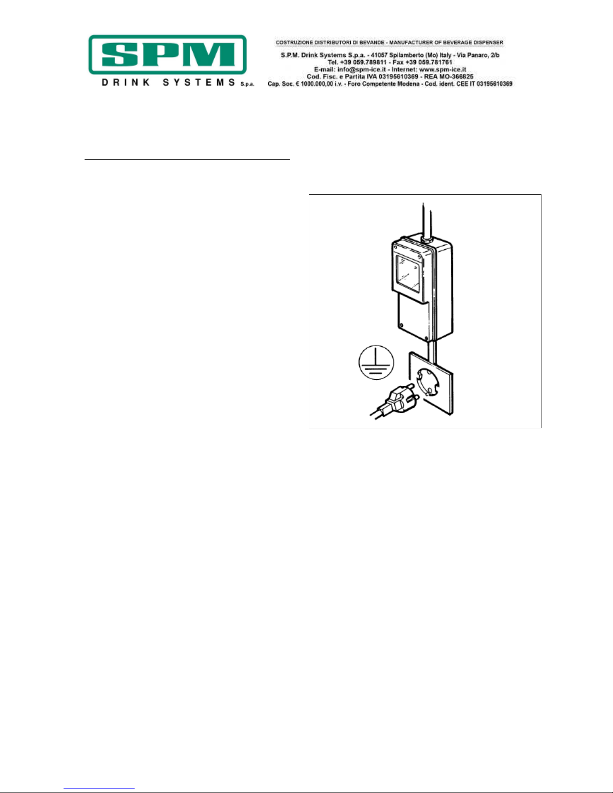
Date de publication: Juin, 2013 Révision: 7 Page : 54/76
7. BRANCHEMENT AU RÉSEAU
ÉLECTRIQUE
POUR L'AGENT D'ENTRETIEN UNIQUEMENT
Avant d'introduire la fiche dans la prise
d'alimentation, comme expliqué dans le
paragraphe précédent, il est nécessaire pour
votre sécurité de prendre connaissance des
précautions suivantes:
- S'assurer que l'installation électrique à laquelle
l'appareil est branché soit pourvue d'une mise à
la terre efficace conformément aux normes en
vigueur concernant la sécurité (fig.3). Le
fabricant ne peut être tenu pour responsable
des dommages éventuels causés par l'absence
de mise à la terre de l'installation.
- Ne pas obstruer les grilles de ventilation et de
dissipation de la chaleur. Une mauvaise aération
peut provoquer une chute de rendement, un
mauvais fonctionnement de l'appareil et risque
de l'endommager sévèrement.
- Toujours vérifier les caractéristiques
électriques figurant sur la plaque de chaque
appareil. Les données de la plaque prévalent
toujours sur les spécifications indiquées dans la
présente notice.
- Il est nécessaire, pour une installation
correcte et sûre, de prévoir une prise spécifique
commandée par un interrupteur
magnétothermique qui doit avoir une distance
d'ouverture entre les contacts d'au moins 3 mm
conformément aux normes nationales sur la
sécurité en vigueur (fig.3).
- Ne jamais utiliser de prises multiples ou de
rallonges.
- S'assurer que le cordon d'alimentation sur
toute sa longueur ne risque d'être écrasé
d'aucune manière.
- Pour débrancher la fiche, la saisir et la tirer
doucement toujours après avoir désactivé
l'interrupteur général.
Important
SI LE CORDON D'ALIMENTATION EST
ENDOMMAGÉ, SON REMPLACEMENT DOIT
ÊTRE EFFECTUÉ PAR LE FABRICANT OU SON
SERVICE APRÈS-VENTE OU EN TOUT CAS PAR
UNE PERSONNE QUALIFIÉE, AFIN D'ÉVITER
TOUT RISQUE.
Fig. 3

Date de publication: Juin, 2013 Révision: 7 Page : 55/76
8. OPÉRATIONS DE DÉMARRAGE
!ATTENTION!
AVANT LA PREMIÈRE MISE EN MARCHE DE
L'APPAREIL, EFFECTUER LES OPÉRATIONS DE
NETTOYAGE ET DE DÉSINFECTION DÉCRITES AU
CHAPITRE 12
- Diluer et mélanger dans un récipient à part le
sirop avec de l'eau en respectant les indications
du fabricant (voir figure 4); ne jamais verser de
poudres sèches, de cristaux ou de sirop
concentré directement dans la cuve vide.
!ATTENTION!
S'assurer que la teneur en sucre du mélange
soit comprise entre 12,5 % et 13,5 %; une
concentration plus faible peut endommager
sévèrement les organes de malaxage et les
moteurs.
NE JAMAIS UTILISER D'EAU SEULE.
- Ôter le couvercle lumineux après l'avoir
débloqué avec la clé prévue à cet effet, en
tournant dans le sens horaire (fig.5).
- Retirer le sous-couvercle transparent (fig.6).
- Verser le produit obtenu dans la cuve (voir
fig.7).
- Replacer le sous-couvercle et par la suite le
couvercle lumineux, en faisant attention à ce
que ce dernier appuie sur le dispositif de
sécurité.
- Bloquer enfin le couvercle lumineux avec la clé
prévue à cet effet en tournant dans le sens
antihoraire.
Remarque ----------------------------------------
------L'appareil IPro est muni d'un dispositif de
sécurité efficace qui protège l'opérateur: il se
déclenche lorsque le couvercle est soulevé et
provoque l'arrêt immédiat et automatique de
tous les organes en mouvement.
L'appareil ne peut donc pas fonctionner si
le couvercle n'est pas correctement en
place.
------------------------------------------------------
- Introduire la fiche dans la prise d'alimentation
électrique et activer l'interrupteur général.
Fig. 4
Fig. 5
Fig. 6
Fig. 7
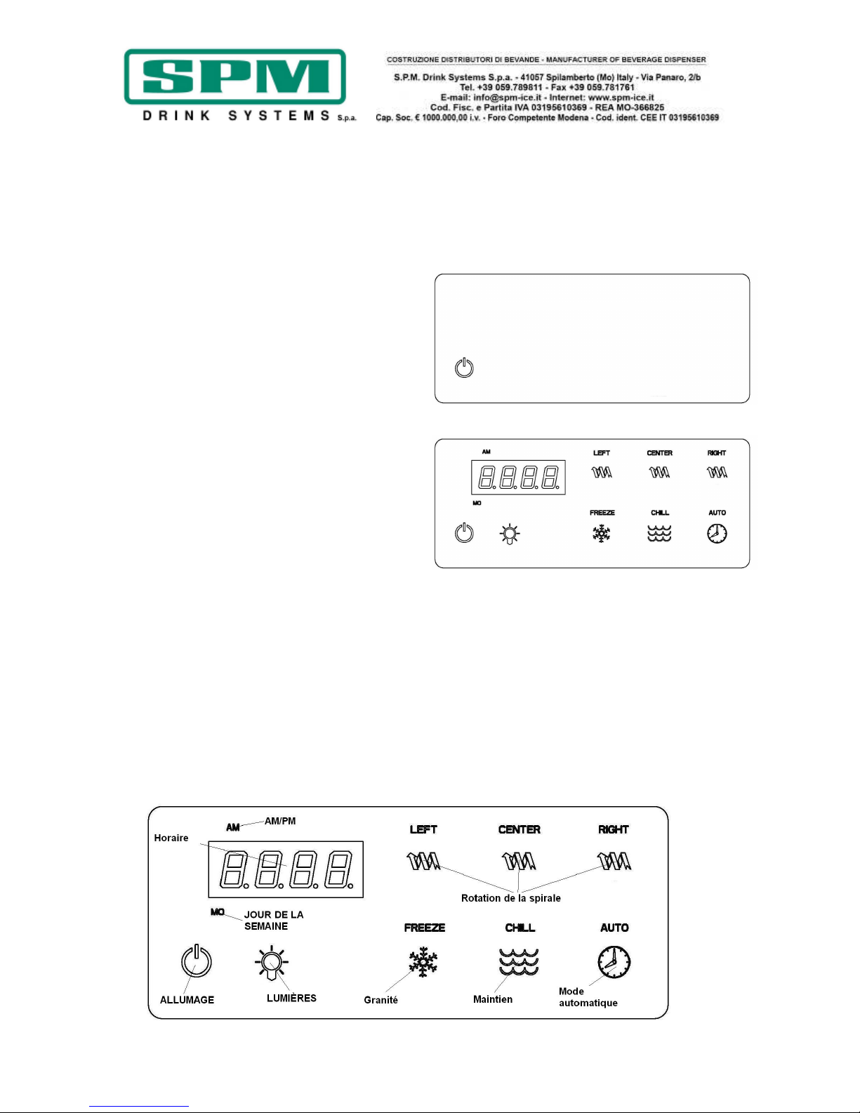
Date de publication: Juin, 2013 Révision: 7 Page : 56/76
9. VERSION ÉLÉCTRONIQUE -
EXPLICATION DES
INTERRUPTEURS ET MODE
D'EMPLOI
Fonctionnement manuel
Après avoir introduit la fiche dans la prise de
courant, la machine est prête à être allumée; le
tableau de commande se présente comme celui
montré dans la figure 8.
En touchant l'afficheur capacitif avec un doigt en
correspondance de la touche d'allumage/arrêt,
l'afficheur s'allume et se présente comme celui
montré dans la figure 9; la machine est
maintenant prête à fonctionner en mode
manuel.
Le fonctionnement de chaque touche capacitive
est expliqué ci-dessous:
ALLUMAGE: elle allume et éteint la machine.
LUMIÈRES: elle allume et éteint les lumières qui
illuminent les couvercles et les cuves.
AM/PM: si l'on choisit la modalité 12 heures, ces
deux indicateurs indiquent la partie de la
journée.
JOUR DE LA SEMAINE: elle indique le jour de la
semaine.
LEFT-CENTER-RIGHT: ces trois touches activent
et désactivent la rotation de la spirale
correspondante.
FREEZE: en activant cette touche la machine
fonctionne en modalité granité.
CHILL: en activant cette touche la machine
fonctionne en modalité de maintien.
AUTO: en activant cette touche la machine
commence à fonctionner en mode automatique
selon les paramètres configurés.
Fig. 8
Fig. 9
!ATTENTION!
Ces trois dernières touches, FREEZE, CHILL
et AUTO, peuvent être activées seulement
lorsqu'au moins l'une des trois spirales est
en rotation et évidemment seulement le
système frigorifique correspondant sera
mis en marche.

Date de publication: Juin, 2013 Révision: 7 Page : 57/76
Fonctionnement automatique
En appuyant sur la touche AUTO après avoir
allumé la machine le fonctionnement
automatique sera activé suivant les paramètres
configurés; cela signifie que la machine passera
automatiquement de la modalité granité à celle
de maintien en fonction des jours et des heures
programmés.
Pendant cette phase, les touches FREEZE et
CHILL seront visibles, mais ne pourront pas être
sélectionnées.
Programmation
Pour accéder à la modalité de programmation il
suffit d'appuyer avec le doigt sur la touche
d'allumage pendant 6/7 secondes jusqu'à ce
qu'un signal sonore indique l'activation de la
modalité de programmation.
L'afficheur se présente maintenant comme celui
dans la figure et le fonctionnement des touches
est le suivant:
AUGMENTATION: elle augmente la valeur de la
partie de l'heure que vous êtes en train de
régler.
DIMINUTION: elle diminue la valeur de la partie
de l'heure que vous êtes en train de régler.
CONFIRMER: elle confirme la valeur réglée et la
rend effective.
MODIFIER JOUR: elle permet de faire défiler les
sept jours de la semaine afin de pouvoir régler
le jour courant.
MODALITÉ HEURE: elle permet de choisir l'une
des deux modalités 12h/24h.
RÉGLAGE DÉBUT/FIN: elle permet de passer de
l'heure de début à l'heure de fin de la modalité
de refroidissement.
SORTIE: elle permet de sortir de la modalité
programmation.

Date de publication: Juin, 2013 Révision: 7 Page : 58/76
Lorsque vous accédez à la phase de
programmation vous pouvez effectuer les
réglages suivants:
• RÉGLAGE HEURE, JOUR ET MODALITÉ
HEURE
Dès que vous accédez à la modalité
programmation, vous pouvez régler le jour
courant au moyen de la touche "MODIFICA
GIORNO" (MODIFIER JOUR); il faut appuyer sur
cette touche jusqu'à ce que vous voyez le jour
que vous souhaitez régler.
Après avoir réglé le jour, vous pouvez
également sélectionner la modalité avec laquelle
vous voulez afficher l'heure, en choisissant
entre 12 heures et 24 heures; pour cela, il suffit
de sélectionner la modalité souhaitée en
appuyant sur la touche "MODALITA' ORARIO"
(MODALITÉ HEURE).
Après avoir choisi ces deux paramètres, vous
pouvez également régler l'heure courante;
l'heure clignote sur l'afficheur, avec les touches
augmentation et diminution vous pouvez régler
l'heure souhaitée avec la touche "ENTER"
(ENTRÉE).
Après avoir confirmé l'heure, le chiffre
correspondant aux minutes commencera à
clignoter et de la même manière vous pouvez
modifier cette valeur avec les touches + et -.
Après avoir confirmé les minutes aussi, la
machine passe automatiquement à la
programmation de la journée de la modalité
automatique.
• PROGRAMMATION DE LA JOURNÉE DE LA
MODALITÉ AUTOMATIQUE
Maintenant, seulement le premier jour de la
semaine Lundi (MO) sera visible ainsi que le
message START qui indique le début de la
modalité maintien; l'heure qui clignote sur
l'afficheur signifie qu'il est possible de la
modifier avec les touches + et - et la confirmer
à la fin avec la touche "ENTER" (ENTRÉE).
Après cette confirmation, vous pourrez régler
les minutes et les confirmer de la même
manière.
Après cette confirmation, le message START
disparaîtra alors que le message STOP
apparaîtra pour indiquer qu'il est possible de
régler la fin de la modalité maintien et donc le
début de la modalité de granité.
Une fois réglées et confirmées aussi bien l'heure
que les minutes, le jour passera du lundi (MO)
au mardi (TU) en soulignant que de la même
manière vous pouvez maintenant régler le début
et la fin de la modalité maintien pour le jour
Mardi.
En procédant de cette manière vous pourrez
régler tous les jours de la semaine jusqu'à
Dimanche (SU) et à la fin vous reviendrez au
réglage de l'heure courante.
En appuyant sur la touche "EXIT" (SORTIE), il
est désormais possible de sortir de la modalité
programmation.
NOTA BENE: une fois ces horaires
enregistrés, l'appareil les conserve
automatiquement.
NOTA BENE: lorsque la touche AUTO est
allumée, les paramètres de fonctionnement
automatique sont actifs et les touches
FREEZE et CHILL sont bloquées. Pour
désactiver cette modalité de
fonctionnement, appuyer sur la touche
AUTO et la désactiver.
NOTA BENE: Les intervalles horaires qui
déterminent le fonctionnement de la
machine en mode automatique sont les
mêmes pour les trois cuves.
NOTA BENE: un des agitateurs au moins
doit être en mouvement pour que l'appareil
permette d'activer l'un des deux modes
“COOLING” ou “FREEZING”.

Date de publication: Juin, 2013 Révision: 7 Page : 59/76
Alarme de nettoyage du filtre
L’alarme de nettoyage du filtre se déclenche
lorsque la température interne de l'appareil est
trop élevée. Lorsque cela se produit, le message
"FILTER” s'affiche sur le tableau de commande
tel que montré dans la figure 10.
Pour identifier et résoudre les conditions qui ont
généré l'alarme, voir la liste ci-dessous:
• Condition A : le filtre est sale et doit être
nettoyé.
Intervention conseillée : nettoyer et replacer
le filtre en suivant les instructions
(Nettoyage du filtre du condensateur
PAG.24).
• Condition B : l'appareil est positionné trop
près d'un mur ou d'un autre objet qui en
limitent le flux d'air ce qui oblige la machine
à fonctionner à une température trop élevée.
Intervention conseillée : modifier la position
de l'appareil de façon à optimiser l'espace
disponible pour son aération (voir les
consignes d'installation).
• Condition C : l'appareil a été installé près
d'une source de chaleur qui génère de l'air
chaud ce qui l'oblige à fonctionner à une
température trop élevée (éviter absolument
d'installer l'appareil près d'une source de
chaleur).
Intervention conseillée : repositionner
l'appareil de façon à optimiser la ventilation.
Fig. 10

Date de publication: Juin, 2013 Révision: 7 Page : 60/76
Alarme de température excessive
Lorsque la température interne de l'appareil
atteint la valeur limite prédéfinie par le
fabricant, le message CUT/OUT apparaît sur
l'afficheur (fig.11) et le fonctionnement du
circuit frigorifique est bloqué afin d'éviter des
dommages au compresseur.
• Le système passe automatiquement en
mode “OFF” qui désactive le compresseur,
seules les spirales continuent à fonctionner
afin d'éviter la formation de blocs de glace.
• Lorsque cela se produit le message
“CUT/OUT” apparaît sur l'afficheur (fig.11).
• Lorsque cela se produit il faut éteindre tous
les interrupteurs et évaluer les conditions et
les actions relatives à mener décrites au
paragraphe concernant l'alarme de
nettoyage du filtre à la page 15.
Fig. 11
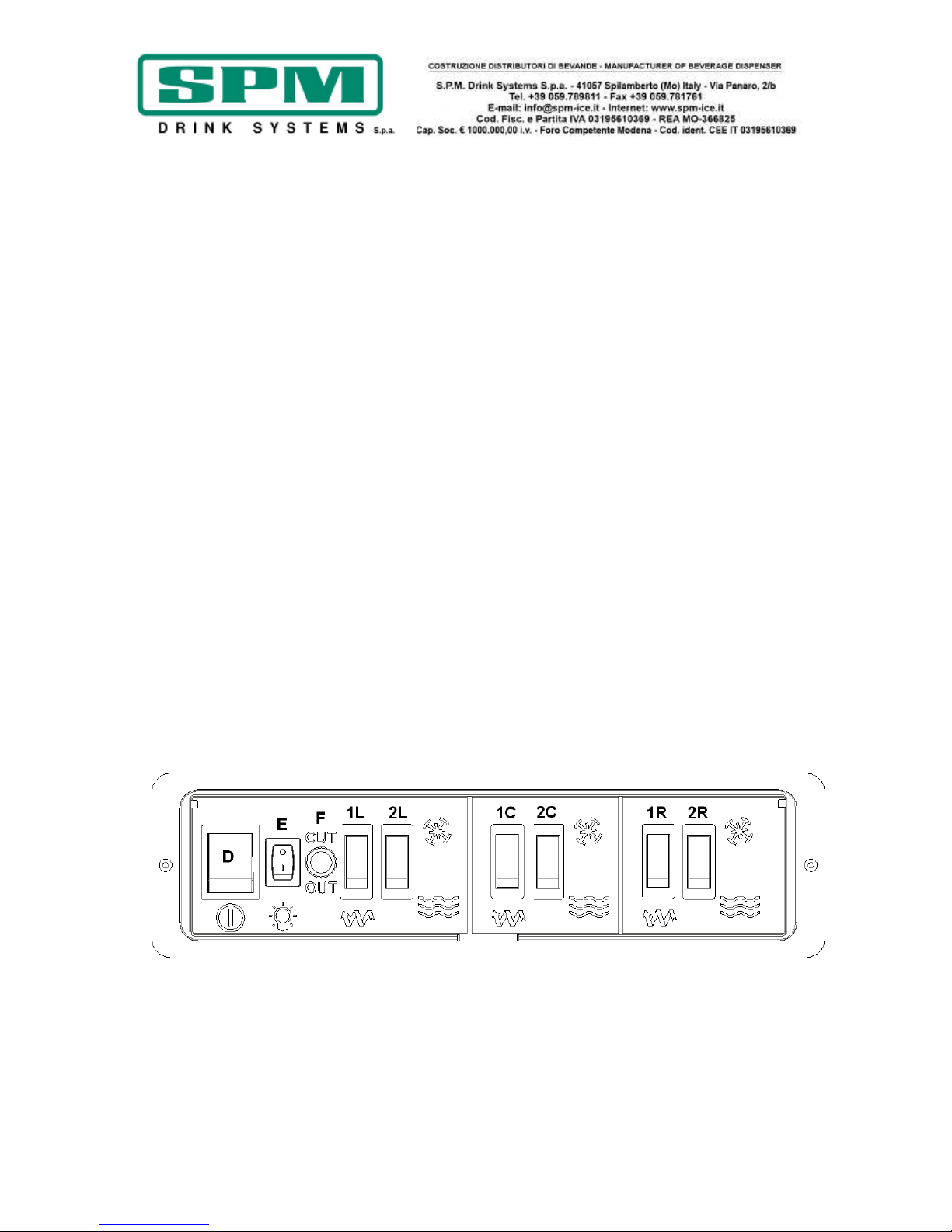
Date de publication: Juin, 2013 Révision: 7 Page : 61/76
10. VERSION MÉCANIQUE -
EXPLICATION DES
INTERRUPTEURS ET MODE
D'EMPLOI
a) Activer l'interrupteur général D;
b) Chaque cuve est commandée par 2
interrupteurs qu'il faut actionner de la façon
suivante:
- Pour obtenir un granité ou un sorbet :
sélectionner l'interrupteur 1 (L pour la cuve
gauche, C pour la cuve centrale et R pour la
cuve droite) qui met en marche les organes de
malaxage et ensuite l'interrupteur 2 en
correspondance du flocon de neige pour activer
le circuit frigorifique en mode congélation.
- pour activer la phase de maintien: sélectionner
l'interrupteur 1 (L pour la cuve gauche, C pour
la cuve centrale et R pour la cuve droite) qui
met en marche les organes de malaxage et
ensuite sélectionner l'interrupteur 2 en
correspondance des vagues pour activer le
système de refroidissement qui maintiendra la
température en fonction des paramètres du
thermostat interne.
c) La touche E permet d'allumer et éteindre les
lumières LED des couvercles
! Attention !
Si l'on éteint l'appareil le soir avec les cuves
pleines, même partiellement, une couche de
glace solide peut se former à la surface sous
l'effet de la séparation naturelle du produit qui
n'est pas malaxé. Dans ce cas, avant de
rallumer l'appareil, il est préférable d'enlever
cette couche de glace superficielle qui pourrait
endommager la vis mélangeuse.

Date de publication: Juin, 2013 Révision: 7 Page : 62/76
11. MODE D'EMPLOI
c) Pour servir le produit, placer le verre sous le
robinet et tirer le levier comme il est montré
dans la figure 12.
d) Réglage de la consistance: pour modifier
la consistance du produit, intervenir sur le
bouton de réglage A située à l'arrière de
l'appareil (fig. 13); comme il est mis en
évidence sur l'échelle B, la tourner dans le
sens horaire pour obtenir un produit moins
dense, et dans le sens antihoraire pour
obtenir un produit plus dense.
Attention
Ce dispositif modifie seulement la consistance
du produit à servir (plus ou moins dense) mais
n'a aucun effet sur la température de
refroidissement.
Attention
Lorsque le niveau de granité dans la cuve
descend sous la vis mélangeuse, compléter le
niveau pour éviter que le produit ne devienne
trop dense.
Fig. 12
Fig. 13
Date de publication: Juin, 2013 Révision: 7 Page : 63/76
12. OPÉRATIONS DE NETTOYAGE ET
DE DÉSINFECTION QUOTIDIENNES
Pour maintenir un bon fonctionnement de
l'appareil et respecter les normes d'hygiène en
vigueur, il faut impérativement effectuer
minutieusement et fréquemment les opérations
de nettoyage et de désinfection décrites ciaprès, en s'assurant que la personne chargée de
les effectuer se soit d'abord lavé et désinfecté
les mains et les avant-bras.
Si l'appareil est resté inutilisé pendant une
longue période (saison), il faut toujours
effectuer ces opérations avant de le remettre en
marche.
Attention
Afin d'éviter tout risque d'électrocution
pendant les opérations de nettoyage, ne
pas faire gicler d'eau sur les interrupteurs
et éviter que les composants électriques
internes n'entrent en contact avec l'eau et
les produits utilisés.
Attention
Pour prévenir la formation de bactéries,
n'utiliser que des produits indiqués pour la
désinfection d'objets en plastique et
caoutchouc ; l'inobservation de cette règle
peut comporter des risques sanitaires.
NOTA BENE: l'utilisateur doit connaître les
normes en vigueur de manière à respecter les
lois fédérales, nationales ou locales en matière
de fréquence du nettoyage et de conservation
des produits utilisés.
Les procédures décrites ci-après sont
essentielles pour empêcher la formation de
bactéries et maintenir l'appareil en parfaites
conditions d'hygiène.
Nous conseillons d'effectuer quotidiennement
ces procédures et, en tout cas, en respectant
toujours les normes en vigueur.
Ni le fabricant de l'appareil ni le fabricant de la
préparation alimentaire introduite dans celui-ci
ne peuvent être tenus pour responsables
d'éventuels dommages, directs ou indirects, aux
personnes causés par le non respect des
prescriptions contenues dans la présente notice,
notamment les avertissements concernant le
nettoyage et la désinfection de l'appareil.

Date de publication: Juin, 2013 Révision: 7 Page : 64/76
NETTOYAGE ET DÉSINFECTION
QUOTIDIENS
- Désactiver le circuit frigorifique (en
désactivant avec la touche avec le flocon de
neige ou avec celle avec les vagues) et faire
fonctionner la machine avec seulement le
mélangeur en mouvement pendant une dizaine
de minutes.
- Vider le produit qui reste dans la cuve.
Attention
Afin d'éviter tout risque d'électrocution ou
de contact avec des pièces en mouvement
pendant les opérations de démontage et
remontage, s'assurer que les interrupteurs
soient bien en position "off" et que le
cordon d'alimentation soit débranché du
réseau.
- Ôter le couvercle lumineux après l'avoir
débloqué avec la clé prévue à cet effet.
- Remplir la cuve avec de l'eau tiède afin de
faire fondre le sucre résiduel puis vider toute
l'eau avant de poursuivre.
- Dévisser et enlever les poignées (voir fig.14).
- Bouger délicatement la cuve comme il est
indiqué dans la figure 15 et en même temps la
tirer vers l'extérieur afin de pouvoir la libérer de
son emplacement.
- Appuyer en même temps sur les deux ailettes
de blocage Q et soulever le robinet I pour
l'extraire de son siège (voir fig.16).
- Démonter le robinet en exerçant une pression
vers le bas sur le corps L et extraire le levier R
de son emplacement (voir fig.17).
Attention
Pour éviter la formation de bactéries,
enlever et nettoyer toujours les joints
toriques et leurs emplacements; le non
respect de cette consigne peut générer un
risque pour la santé des consommateurs.
Fig. 14
Fig. 15
Fig. 16
Fig. 17

Date de publication: Juin, 2013 Révision: 7 Page : 65/76
- Dévisser le bouton de fixation S dans le sens
horaire (filetage gauche) et sortir le groupe
malaxeur U et les joints d'étanchéité X et T (voir
Fig.18).
Attention
Ne pas utiliser de détergents abrasifs qui
pourraient endommager la surface des
composants. Ne pas laver ces composants
dans le lave-vaisselle car des pièces
comme la cuve ou la spirale pourraient être
endommagées.
- Laver soigneusement toutes les pièces
démontées avec de l'eau tiède et du produit
pour vaisselle délicat.
- Se munir d'un produit ordinaire indiqué pour la
désinfection d'objets en plastique et caoutchouc
(AMUCHINA®).
- Bien rincer et plonger chaque partie dans le
produit désinfectant en respectant les doses et
les temps suggérés par le producteur de celuici.
IMPORTANT
Respecter rigoureusement les consignes du
désinfectant utilisé en ce qui concerne les
temps d'utilisation et son mode d'emploi.
- Une fois respectés les temps corrects de
désinfection, rincer attentivement chaque
composant avec de l'eau propre et sécher avec
un chiffon propre.
- Laver soigneusement l'évaporateur Z et le plan
de collecte de la condensation Y, en éliminant
tout résidu de produit avec une éponge propre
imbibée de désinfectant (voir fig.19).
- Répéter les mêmes opérations avec une
éponge imbibée d'eau potable propre et sécher
soigneusement toutes les surfaces avec un
chiffon propre.
Fig. 18
Fig. 19

Date de publication: Juin, 2013 Révision: 7 Page : 66/76
Après avoir soigneusement effectué toutes ces
opérations de nettoyage, vous pouvez remonter
les composants.
Le correct remontage est très important pour
prévenir les fuites de produit et le risque de
détérioration de l'appareil.
Pour remonter l'appareil, il faut disposer d'un
lubrifiant agréé (vaseline).
Toujours s'assurer que chaque pièce ait été
correctement lavée et désinfectée et que la
personne chargée du remontage se soit bien
lavé et désinfecté les mains et les avant-bras.
- Remonter le groupe malaxeur (fig.18) en
respectant les opérations suivantes:
• Graisser le joint ventouse X avec de la
vaseline pour réduire les frottements et
limiter l'usure (fig.20).
• Remonter le joint T en faisant attention à
la direction (fig.21).
• Remonter la spirale U en vérifiant que
l'embout d'entraînement s'encastre
parfaitement dans l'arbre de guidage.
• Fixer tous les composants en vissant le
bouton S dans le sens antihoraire.
- Remonter la cuve dans son emplacement en
vérifiant qu'elle adhère parfaitement à son joint
T (voir Fig.23). Pour faciliter le remontage, nous
conseillons également de lubrifier la partie
arrière de la cuve en contact avec le joint
d'étanchéité (fig.22).
- Fixer la cuve avec les boutons spéciaux et
visser solidement mais sans trop forcer.
IMPORTANT
Ne pas serrer excessivement les boutons
de fixation de la cuve car une force
excessive pourrait endommager le filetage
et/ou la cuve.
Fig. 20
Fig. 21
Fig. 22
Fig. 23

Date de publication: Juin, 2013 Révision: 7 Page : 67/76
- Remonter le robinet en ayant soin de lubrifier
à la vaseline les joints J pour aider le robinet à
glisser dans son emplacement jusqu'à sa
complète introduction (voir Fig. 24).
!ATTENTION!
Si le robinet ne glisse pas parfaitement
dans son siège, son étanchéité peut être
compromise.
- Démonter le bac d'égouttage en le tirant vers
l'extérieur (voir fig.25).
- Laver soigneusement chacune de ses parties.
- Bien rincer et plonger chaque partie dans le
produit désinfectant en respectant les doses et
les temps suggérés par le producteur de celuici.
- Remonter en inversant les opérations décrites
ci-dessus .
- La machine est maintenant prête à être
utilisée de nouveau.
DÉSINFECTION APRÈS DES PÉRIODES
D'INACTIVITÉ
Si la machine reste inactive pendant quelques
jours après avoir été nettoyée et désinfectée
soigneusement comme précédemment décrit,
au moment de la remettre en marche, il est
nécessaire d'effectuer les opérations de
désinfection décrites ci-après.
- Soulever d'abord le couvercle de sécurité, puis
le sous-couvercle.
- Remplir la cuve avec de l'eau et ajouter le
produit pour la désinfection d'objets à usage
alimentaire (AMUCHINA®) en respectant
attentivement les doses indiquées par la société
qui le produit.
- Après avoir replacé le couvercle, faire
fonctionner le malaxeur et laisser agir pendant
le temps nécessaire, qui est aussi précisé par le
fabricant.
Fig. 24
Fig. 25
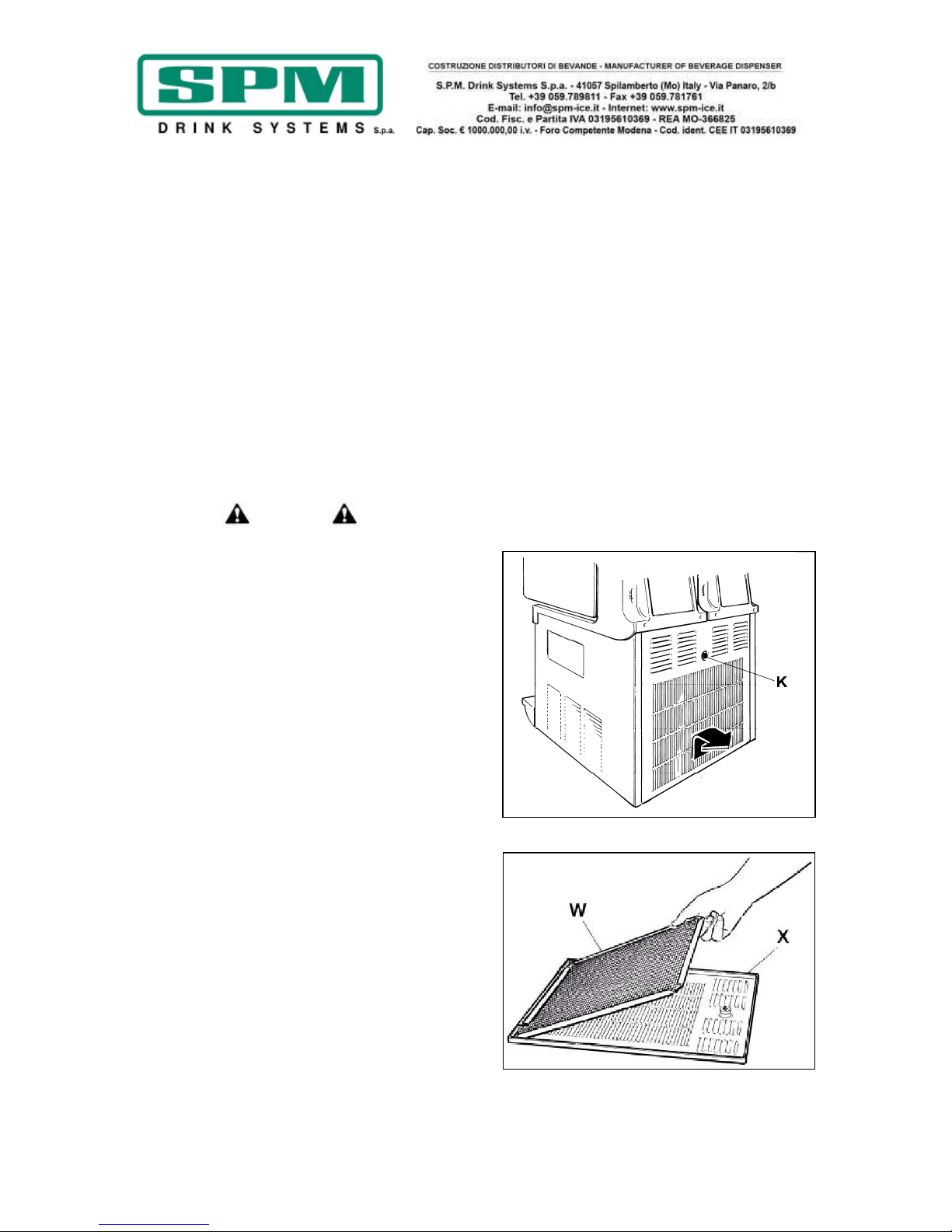
Date de publication: Juin, 2013 Révision: 7 Page : 68/76
IMPORTANT
Ne pas laisser le désinfectant dans la cuve
pendant des périodes de temps supérieures
à celles indiquées par le fabricant
- Vider la cuve en ouvrant et fermant au moins
10 fois le robinet, afin de désinfecter également
la zone de passage du produit.
- Rincer soigneusement en répétant les mêmes
opérations en utilisant seulement de l'eau
potable propre à la place du désinfectant.
- Après avoir soigneusement effectué ces
opérations la machine est prête à être utilisée.
13. ENTRETIEN EXCEPTIONNEL
Attention
Avant toute intervention d'entretien, il faut
obligatoirement éteindre l'appareil et
débrancher le cordon d'alimentation de la
prise de courant.
Nettoyage du filtre du condensateur
Afin de garantir un bon rendement du circuit
frigorifique nous recommandons de
maintenir le filtre du condensateur propre
en le nettoyant fréquemment comme il est
décrit ci-après:
- Couper la tension de l'appareil et débrancher
le cordon d'alimentation.
- Dévisser le bouton K pour enlever le panneau
arrière X (voir fig.26).
- Enlever le filtre du condensateur W et le
nettoyer avec de l'eau ou avec un aspirateur
(voir fig.27).
- Remonter le filtre et le panneau.
!ATTENTION!
Une propreté insuffisante du condensateur
peut entraîner la détérioration de l'appareil
et l'annulation de la garantie.
Fig. 26
Fig. 27

Date de publication: Juin, 2013 Révision: 7 Page : 69/76
Contrôle et remplacement des joints
JOINT DE LA CUVE
Le joint situé à l'arrière de la cuve doit être
remplacé tous les 12 mois en fonction de son
état d'usure et de son niveau d'entretien et de
graissage.
JOINTS TORIQUES DU ROBINET
Les joints toriques du robinet de distribution du
produit doivent être remplacés toutes les fois
qu'ils présentent des traces d'usure. Ces joints
doivent être graissés à chaque remontage de
l'appareil, après le nettoyage, et contrôlés
attentivement pour éviter toute fuite ou perte
indésirable.
JOINT VENTOUSE
Le joint ventouse, situé à l'avant de
l'évaporateur, doit être remplacé tous les 3 mois
et, en tout cas, chaque fois qu'il présente des
traces d'usure ou des signes de détérioration.
Ce joint doit être graissé avec la vaseline en
dotation chaque fois qu'il est remonté après le
nettoyage.
Stockage hivernal
Pour protéger l'appareil pendant une longue
période d'inactivité (en hiver par exemple), il
est important de le stocker correctement en
suivant les consignes ci-dessous:
- Débrancher l'appareil de toute source
d'énergie.
- Démonter, laver et désinfecter toutes les
pièces en contact avec le produit (voir chapitre
12).
- Nettoyer aussi les panneaux externes.
- Remonter parfaitement tous les composants.
- Couvrir l'appareil complètement monté avec
l'emballage d'origine de manière à le protéger
contre la poussière et autres agents
contaminants.
- Placer l'appareil dans un endroit sec.
14. EXCLUSION DE RESPONSABILITÉ
Le fabricant décline toute responsabilité pour les
éventuels dommages, directs ou indirects, aux
personnes, objets, animaux causés par le non
respect des prescriptions indiquées dans la
présente notice concernant notamment
l'installation, l'utilisation et l'entretien de
l'appareil.
La langue officielle est l'Italien, donc le fabricant
décline toute responsabilité concernant les
inexactitudes dues à des erreurs d'impression,
de transcription ou de traduction qui pourraient
se trouver dans ce manuel et se réserve le droit
d'y apporter toute les modifications qu'il estime
nécessaires, y compris dans l'intérêt de
l'utilisateur, n'affectant pas les caractéristiques
essentielles de fonctionnement et de sécurité de
l'appareil.

Date de publication: Juin, 2013 Révision: 7 Page : 70/76
15. GUIDE A LA SOLUTION DES PROBLÈMES
NOTA BENE: les interventions suivantes doivent être effectuées par un technicien
Cause probable Solution
L'appareil ne refroidit
pas ou refroidit
partiellement et le
compresseur ne
fonctionne pas
• L'espace de ventilation autour de
l'appareil n'est pas suffisant
• L'appareil fonctionne en mode
DEFROST
• Le condensateur est sale et
poussiéreux
• Le ventilateur ne fonctionne pas
• Il y a une fuite de réfrigérant
• Laisser un dégagement d'au moins 20 cm
autour de l'appareil et ne pas l'installer à
proximité d'autres sources de chaleur
• Rétablir le mode RÉFRIGÉRATION
• Nettoyer le condensateur en suivant les
consignes décrites
• Contrôler les branchements électriques et
les rebrancher si nécessaire, puis s'il ne
fonctionne toujours pas, remplacer le
ventilateur
• Localiser la fuite, l'éliminer et recharger
le circuit
L'appareil ne refroidit
pas ou refroidit
partiellement et le
compresseur ne
fonctionne pas
• Les pièces électriques du
compresseur ne fonctionnent pas
• Certains branchements électriques
sont incomplets
• Le compresseur est défectueux
• Le courant n'arrive pas à la carte
• Remplacer les composants qui ne
fonctionnent pas
• Vérifier les connexions et rétablir celles
qui sont incomplètes
• Remplacer le compresseur
• Vérifier les branchements électriques à la
carte et les rétablir
L'appareil refroidit trop
ce qui ralentit ou bloque
la rotation de la spirale
• La teneur en sucre du produit est
insuffisante
• La vis de réglage de la consistance
est tarée sur une valeur trop élevée
• Le levier du micro-rupteur de
dureté est plié et n'entre pas en
contact avec le motoréducteur
• Le niveau du produit dans la cuve
est insuffisant
•
La carte n'ouvre pas les contacts
• Vérifier le brix du produit et le corriger
• Régler la vis de dureté vers le "-" pour
diminuer la consistance du produit
• Redresser le levier avec des pinces et
rétablir le contact
• Ajouter du produit ou éteindre le circuit
frigorifique
• Remplacer la carte
L'appareil est bruyant • Les pales du ventilateur heurtent
des composants internes
• Vérifier et remédier à l'incident
L'interrupteur principal
est en position ON, mais
l'appareil ne fonctionne
pas
• Certaines connexions électriques
sont incomplètes
• La carte électronique de commande
est défectueuse
•
Le motoréducteur est défectueux
• Vérifier les connexions et rétablir celles
qui sont incomplètes
• Remplacer la carte de commande
• Remplacer le motoréducteur
La cuve fuit • Un des joints d'étanchéité n'est pas
correctement monté
• Remettre le joint correctement en place
ou, si nécessaire, le remplacer
Le robinet goutte • Le robinet n'a pas été correctement
remonté
• Le mouvement du robinet est
bloqué
• Les joints toriques sont abîmés ou
usés
• Démonter et remonter correctement le
robinet
• Nettoyer le robinet et son emplacement
et lubrifier avec la vaseline en dotation
• Remplacer les joints toriques
Le produit tombe dans le
bac d'égouttage à
travers le tuyau de
drainage
• Le joint ventouse, le moyeu du
malaxeur et le bouton de fixation
n'ont pas été correctement
remontés
• Le joint ventouse ou la bague
d'étanchéité de l'arbre sont
détériorés ou usés
• Démonter et remonter correctement le
système de malaxage
• Démonter et remplacer les joints
d'étanchéité
Le malaxeur ne tourne
pas
• Certaines connexions électriques
sont incomplètes
• La carte électronique est
défectueuse
•
Le motoréducteur est défectueux
• Vérifier les connexions et rétablir celles
qui sont incomplètes
• Remplacer la carte
• Remplacer le motoréducteur

Date de publication: Juin, 2013 Révision: 7 Page : 71/76
Anomalie Cause probable Solution
Le malaxeur est bruyant
pendant la rotation
• Le joint ventouse a été remplacé
sans avoir été correctement lubrifié
• La spirale de malaxage n'a pas été
correctement remontée
• Démonter, nettoyer, désinfecter et
lubrifier correctement le joint
• Démonter et remonter correctement la
spirale et tout le système de malaxage
Sur l'afficheur de la
carte apparaît un des
messages suivants
“FILTER” ou “CUT/OUT”
Le voyant rouge sur le
tableau de commande
est allumé
• Le filtre est sale et doit être nettoyé
• L'appareil est positionné trop près
du mur ou d'autres objets qui
gênent le passage de l'air de
refroidissement ce qui oblige
l'appareil à fonctionner à une
température trop élevée
• Le filtre n'est pas monté
correctement
• L'appareil est installé prés d'autres
sources de chaleur ce qui l'oblige à
fonctionner à une température trop
élevée
• Démonter, nettoyer et remonter le filtre
en suivant les indications décrites
• Repositionner l'appareil de façon à
optimiser la ventilation
• Installer correctement le filtre
• Repositionner l'appareil de façon à
optimiser la ventilation

Date de publication: Juin, 2013 Révision: 7 Page : 72/76
16. SCHEMA ELETTRICO -WIRING DIAGRAM
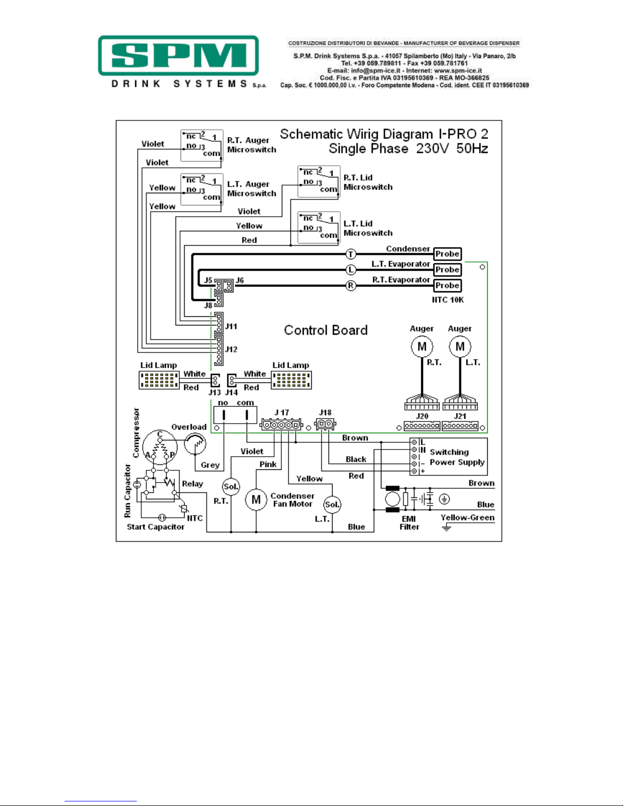
Date de publication: Juin, 2013 Révision: 7 Page : 73/76
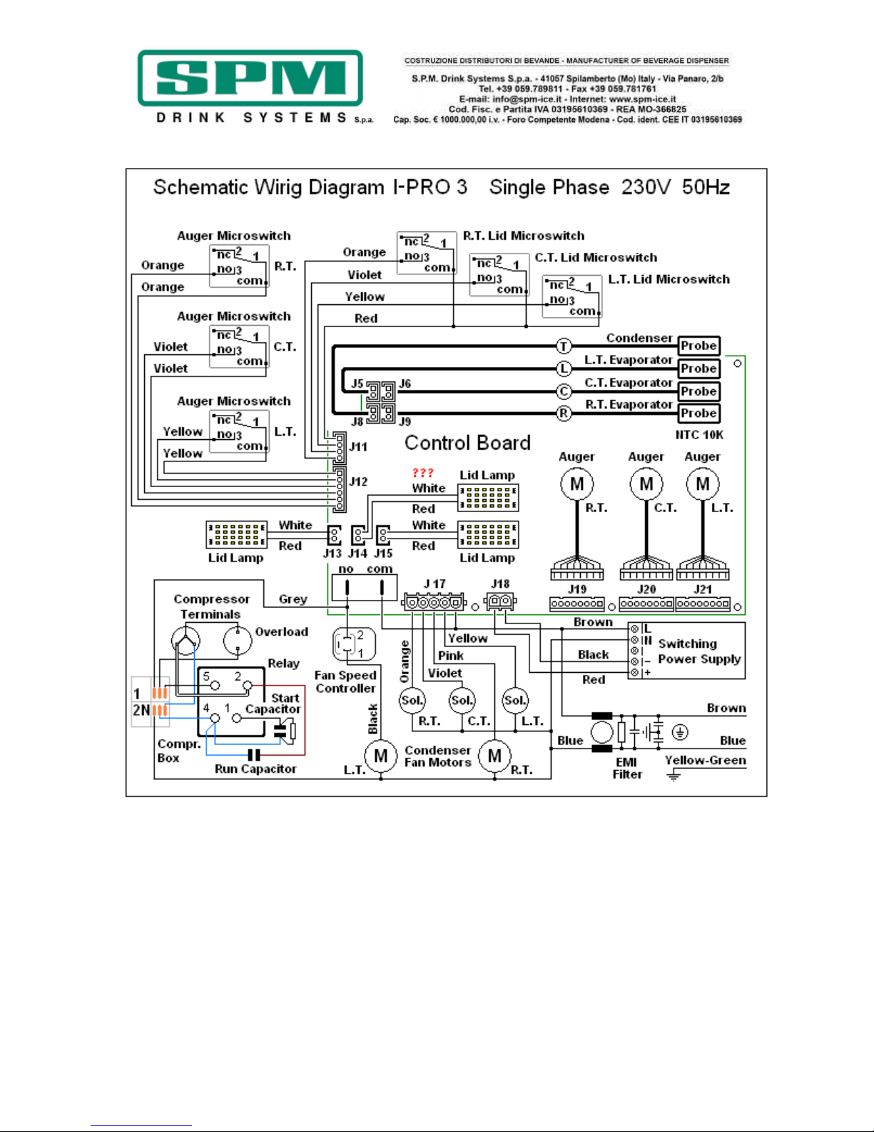
Date de publication: Juin, 2013 Révision: 7 Page : 74/76

Date de publication: Juin, 2013 Révision: 7 Page : 76/76
Conforme alla normativa RoHS
Questo apparecchio è conforme alla direttiva europea 2002/95/CE e successive modifiche per quanto riguarda la restrizione all’uso di
sostanze pericolose nella produzione di apparecchiature elettriche ed elettroniche.
Smaltimento
Ai sensi della direttiva RAEE 2002/96/CE e successiva modifica 2003/108/CE questa apparecchiatura viene contrassegnata con il
seguente simbolo del contenitore di spazzatura con ruote barrato. “ INFORMAZIONE AGLI UTENTI: Ai sensi dell’art. 13 del Decreto
Legislativo 25 Luglio 2005 n. 151 - Attuazione delle Direttive 2002/95/CE e 2002/96/CE, relative alla riduzione dell’uso di sostanze
pericolose nelle apparecchiature elettriche ed elettroniche, nonché allo smaltimento dei rifiuti. Il simbolo del cassonetto barrato indica
che il prodotto, alla fine della sua vita utile, deve essere raccolto separatamente dagli altri rifiuti. L’utente deve conferire
l’apparecchiatura giunta a fine vita ad idonei centri di raccolta differenziata dei rifiuti elettrici ed elettronici, oppure consegnarla al
rivenditore al momento dell’acquisto di nuova apparecchiatura di tipo equivalente, in ragione di uno ad uno. L’adeguata raccolta
differenziata per l’avvio successivo al trattamento e allo smaltimento ambientalmente compatibile contribuisce ad evitare possibili effetti
negativi sull’ambiente e sulla salute e favorisce il reimpiego e il riciclo dei materiali di cui è composta l’apparecchiatura. Lo smaltimento
abusivo del prodotto da parte dell’utente comporta l’applicazione delle sanzioni amministrative di cui al D.Lgs. n.22/1997.”
Company
with certified quality
management system
UN EN ISO 9001
 Loading...