

Page 1

Data di emissione: Aprile, 2011 Revisione: 1 Pag. : 1/124
GRANITORE
SLUSH MACHINE
GRANITAMASCHINE
APPAREIL À GRANITÉS
Ice Dream
MANUALE D’USO E MANUTENZIONE
OPERATOR’S MANUAL
GEBRAUCHS- UND
WARTUNGSANLEITUNG
NOTICE D'UTILISATION ET
D'ENTRETIEN
ITALIANO PAG.2
ENGLISH PAGE 29
DEUTSCH SEITE 56
FRANÇAIS PAGE 84
Page 2
Data di emissione: Aprile, 2011 Revisione: 1 Pag. : 2/124
Pubblicazione emessa da:
SPM DRINK SYSTEMS S.p.A.
Via Panaro n° 2
41057 Spilamberto (MO)
Edizione: 04/2011
Revisione: 01
© 2011 – SPM Drink Systems
Tutti i diritti di riproduzione del presente manuale sono riservati alla SPM DRINK SYSTEMS, la riproduzione anche
parziale è vietata.
Le descrizioni e le illustrazioni sono riferite alla specifica macchina/impianto in oggetto. SPM DRINK SYSTEMS si
riserva il diritto di apportare in qualsiasi momento tutte le modifiche che riterrà opportune alla produzione di serie.
Il presente manuale:
è parte integrante della fornitura e deve essere letto attentamente al fine di un utilizzo corretto, in
conformità ai requisiti essenziali di sicurezza;
è elaborato secondo le disposizioni della Direttiva Macchine 2006/42/CE e riporta le informazioni
tecniche necessarie per svolgere correttamente tutte le procedure in condizioni di sicurezza;
deve essere conservato con cura (protetto in un involucro trasparente e stagno per evitarne il
deterioramento) e deve accompagnare la macchina durante tutta la sua vita, compresi eventuali passaggi di
proprietà. In caso di smarrimento o deterioramento è possibile riceverne una copia facendo richiesta alla
SPM DRINK SYSTEMS segnalando i dati riportati sulla targhetta d’identificazione
SPM DRINK SYSTEMS declina ogni responsabilità per uso improprio della macchina/impianto e/o per danni causati
in seguito ad operazioni non contemplate in questo manuale.
Gentile Cliente,
ci congratuliamo con Lei per aver scelto un
prodotto di qualità che sicuramente
risponderà alle Sue aspettative.
RingraziandoLa per la preferenza accordataci,
la invitiamo cortesemente a prendere attenta
visione del presente manuale d’uso e
manutenzione.
Page 3

Data di emissione: Aprile, 2011 Revisione: 1 Pag. : 3/124
INDICE
1. AVVERTENZE E CONSIGLI IMPORTANTI
......................................................................4
2. CORREDO DELL’APPARECCHIO ............4
3. INDICAZIONI UTILI PER IL TRASPORTO4
4. INDICAZIONI UTILI PER IL
SOLLEVAMENTO .....................................4
5. SPECIFICHE TECNICHE ............................5
6. POSIZIONAMENTO ....................................6
7. COLLEGAMENTO ALLA RETE
ELETTRICA ................................................7
8. OPERAZIONI DI AVVIAMENTO ..............8
Versione raffreddamento ad acqua ................... 9
9. SPIEGAZIONE DEGLI INTERRUTTORI E
RELATIVO USO.......................................10
Versione meccanica ........................................ 10
Versione PLUS elettronica ............................. 12
10. MODALITA’ D’USO ..................................19
11. OPERAZIONI DI PULIZIA E
SANITIZZAZIONE QUOTIDIANA ........20
12. MANUTENZIONE STRAORDINARIA ....25
Pulizia filtro condensatore .............................. 25
Sostituzione neon coperchio ........................... 25
Controllo e sostituzione delle guarnizioni ...... 26
Stoccaggio invernale ....................................... 26
13. ESCLUSIONE DI RESPONSABILITA’ ....26
14. GUIDA ALLA RISOLUZIONE DEI ..........27
15. SCHEMI ELETTRICI ...............................112
Page 4

Data di emissione: Aprile, 2011 Revisione: 1 Pag. : 4/124
1. AVVERTENZE E CONSIGLI
IMPORTANTI
Il presente manuale d’uso ed installazione
è parte integrante dell’apparecchio e dovrà
essere conservato per qualsiasi
consultazione. Salvo diversa indicazione, il
presente manuale è rivolto all’operatore
(personale che usa quotidianamente
l’apparecchio) e al manutentore (personale
qualificato per installazione e/o
manutenzione). Le parti del manuale
rivolte solo al manutentore verranno
opportunamente evidenziate. Leggere
attentamente le avvertenze contenute nel
presente manuale prima di installare ed
utilizzare l’apparecchio.
Il presente apparecchio è stato progettato
per la produzione di granite, sorbetti e
prodotti similari preparati miscelando
acqua o latte con sciroppi.
Al momento del ricevimento di questo
apparecchio assicurarsi che il codice di
identificazione dello stesso corrisponda
a quello da Voi ordinato e riportato sempre
sui documenti di trasporto e cioè:
- “nome apparecchio” seguito dal numero
di matricola progressivo.
Questo apparecchio è destinato solo ed
esclusivamente all’uso per il quale è stato
concepito ed il costruttore non può essere
ritenuto responsabile per eventuali danni
dovuti ad un uso improprio.
Il presente apparecchio non è da intendersi
adatto all’uso da parte di persone (incluso
bambini) con ridotte capacità fisiche,
sensoriali o mentali, o prive di esperienza e
conoscenza, a meno che siano state
supervisionate o istruite riguardo all’uso
dell’apparecchio da una persona
responsabile della loro sicurezza. I bambini
dovrebbero essere supervisionati per
assicurarsi che non giochino con
l’apparecchio.
Il presente apparecchio non è adatto
all’uso esterno. Il presente apparecchio
non è adatto all’installazione in luoghi in
cui può essere utilizzato un getto d’acqua.
Il presente apparecchio deve essere
installato in luoghi dove possa essere
controllato da personale qualificato.
2. CORREDO DELL’APPARECCHIO
Al momento dell’apertura all’interno dell’imballo
si troveranno i seguenti elementi:
- il presente manuale di uso e manutenzione,
- la dichiarazione di conformità CE;
- 1 tubetto di lubrificante (vaselina);
- 1 vaschetta raccogli gocce e 1 guarnizione a
ventosa per ciascuna vasca.
3. INDICAZIONI UTILI PER IL
TRASPORTO
Al fine di evitare che l’olio contenuto nel
compressore ermetico defluisca nel circuito
refrigerante, è necessario trasportare,
immagazzinare e movimentare l’apparecchio in
posizione verticale rispettando le indicazioni
poste sull’imballo. Nel caso in cui l’apparecchio
sia stato accidentalmente o volutamente per
ragioni di trasporto, tenuto in posizione non
verticale è necessario, prima del suo
avviamento, tenerlo per circa 3-4 ore in
posizione verticale in modo che l’olio ritorni nel
compressore.
4. INDICAZIONI UTILI PER IL
SOLLEVAMENTO
Ogni apparecchio è munito di un apposito
bancale in legno che ne permette lo
spostamento utilizzando gli usuali mezzi di
movimentazione e di sollevamento.
Attenzione
Non sollevare mai l’apparecchio
singolarmente, ma con l’aiuto di un altro
operatore.
Per non provocare danni all'apparecchio, le
manovre di carico e scarico sono da effettuarsi
con particolare cura. E' possibile sollevare
l'apparecchio, con carrello elevatore, a motore o
manuale, posizionando le pale nella parte
sottostante dello stesso.
Page 5
Data di emissione: Aprile, 2011 Revisione: 1 Pag. : 5/124
Va, invece, evitato di:
- rovesciare l’apparecchio;
- trascinare l’apparecchio con funi od altro;
- sollevare l’apparecchio con imbracature o funi
- scuotere o dare scossoni all’apparecchio ed al
suo imballo.
Per lo stoccaggio è necessario che l'ambiente sia
asciutto e con temperature comprese tra 0°C e
40 °C. Con l'imballo originale è possibile
sovrapporre non più di 2 apparecchi avendo
cura di mantenere la posizione verticale indicata
dalle frecce sull'imballo.
5. SPECIFICHE TECNICHE
Caratteristiche tecniche ed elettriche
dell’apparecchio
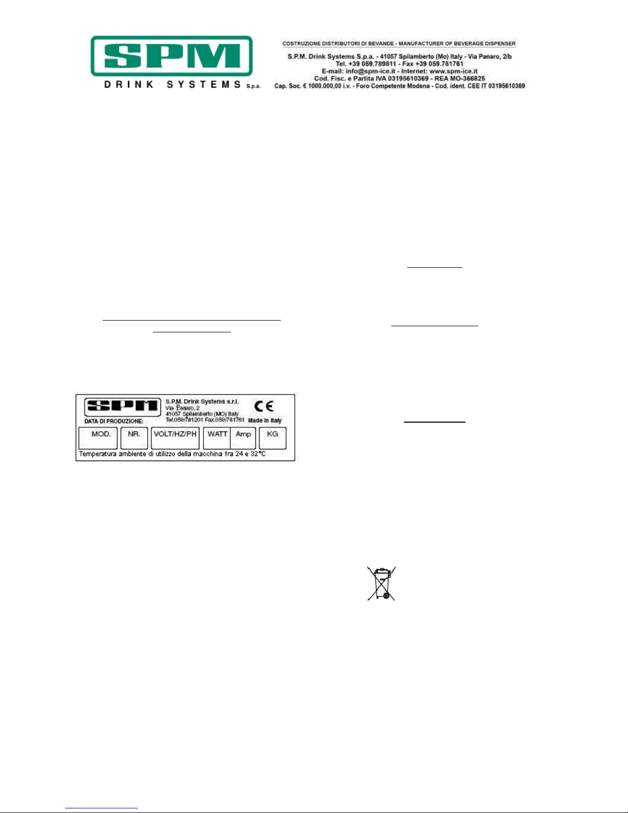
Tutte le caratteristiche tecniche ed elettriche
dell’apparecchio sono riportate sulla targhetta
matricola applicata all’interno dell’apparecchio e
qui sotto riprodotta.
Sulla targhetta vengono riportati:
• Modello;
• Numero di matricola;
• Caratteristiche elettriche in Volt/ Hz;
• Assorbimento max in Watt;
• Corrente max in Amp;
• Peso in kg;
• Temperatura ambiente di utilizzo della
macchina compresa fra i 24 ed i 32°C.
Le dimensioni di ingombro dell’ apparecchio
sono:
Ice Dream 1
• Altezza 85 cm.
• Larghezza 19.5 cm.
• Profondità 56 cm.
• Peso 40 kg.
Ice Dream 2
• Altezza 85 cm.
• Larghezza 40 cm.
• Profondità 56 cm.
• Peso 60 kg.
Ice Dream 3
• Altezza 85 cm.
• Larghezza 60 cm.
• Profondità 56 cm.
• Peso 100 kg.
Rumorosità
Il livello di pressione acustica continuo,
equivalente, ponderato è inferiore a 70 dB.
In caso di guasto:
Nella maggior parte dei casi, gli eventuali
inconvenienti tecnici sono risolvibili con piccoli
interventi; suggeriamo perciò di leggere
attentamente il presente manuale, prima di
contattare il costruttore o il centro di assistenza.
Smaltimento
Importante
Tutti gli elementi dell’imballaggio non devono
essere lasciati alla portata dei bambini in quanto
potenziali fonti di pericolo.
Importante
Nel rispetto dell’ambiente, non disperdere gli
elementi dell’imballaggio ma conservarli in
modo da poterli riutilizzare qualora necessario
(i.e. stoccaggio invernale).
Il simbolo indica che l'apparecchio non
può essere smaltito come rifiuto comune, ma
deve essere smaltito secondo quanto stabilito
dalla direttiva europea 2003/108/CE (Waste
Electrical and Electronics Equipments - WEEE) e
dalle legislazioni nazionali derivanti, per
prevenire possibili conseguenze negative per
l'ambiente e per la salute umana.
Per il corretto smaltimento dell’apparecchio,
contattate il punto vendita presso cui avete
acquistato l’apparecchio oppure il nostro servizio
post vendita.
Page 6
Data di emissione: Aprile, 2011 Revisione: 1 Pag. : 6/124
6. POSIZIONAMENTO
SOLO PER MANUTENTORE
L'installazione e le successive operazioni di
manutenzione, devono essere effettuate da
personale specializzato ed addestrato
all'uso dell'apparecchio, secondo le norme
in vigore.
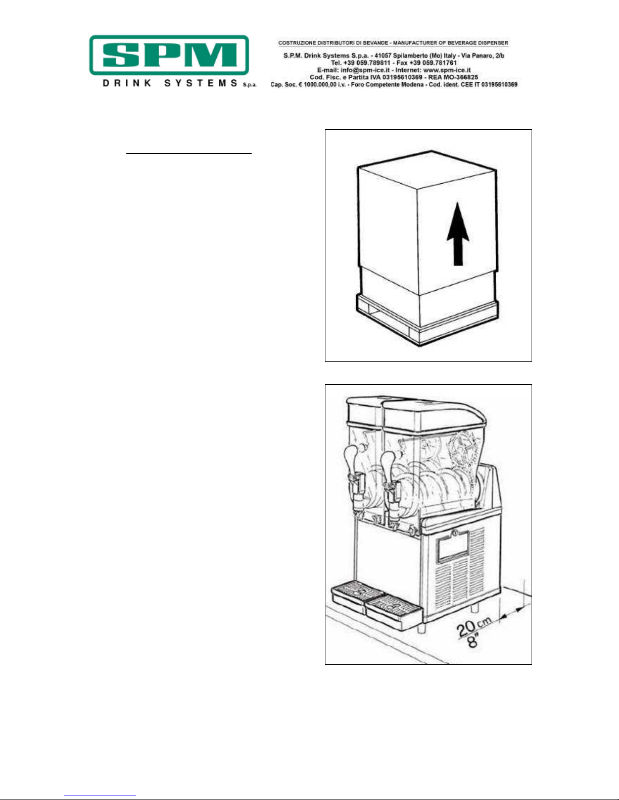
a) Dopo aver tolto l’imballo conservarne tutti
gli elementi per lo stoccaggio invernale ed
assicurarsi dell’integrità dell’apparecchio (fig.1).
!IMPORTANTE!
Tutti gli elementi dell’imballaggio non
devono essere lasciati alla portata dei
bambini in quanto potenziali fonti di
pericolo.
b) Appoggiare l’apparecchio su una superficie
orizzontale e solida facendo in modo che la
carrozzeria dell’apparecchio sia ben areata
(almeno 20 cm di spazio libero, fig.2), installare
l’apparecchio in un ambiente asciutto ed evitare
di installarlo vicino a fonti di calore. La
temperatura ambiente di utilizzo macchina
deve essere compresa tra i 24°C e i 32°C.
c) Controllare che la tensione di rete
corrisponda a quella indicata sulla targhetta
matricola e che la potenza disponibile sia
adeguata a quella richiesta dall’apparecchio.
Inserire la spina in una presa di corrente munita
del polo di terra, eliminando prese multiple.
PER ULTERIORI PRECAUZIONI, LEGGERE
ATTENTAMENTE IL PARAGRAFO
“COLLEGAMENTO ALLA RETE ELETTRICA”.
d) L’installazione deve essere effettuata secondo
le istruzioni del produttore. Un mancato rispetto
di tali indicazioni può compromettere la
funzionalità dell’apparecchio.
Importante
La messa a terra è necessaria e obbligatoria a
termine di legge. Prima di effettuare qualsiasi
operazione di pulizia o manutenzione
straordinaria assicurarsi di aver scollegato
l’apparecchio dalla rete togliendo la spina di
alimentazione.
In caso di guasto o mal funzionamento spegnere
l’apparecchio e staccare la spina.
Fig. 1
Fig. 2
Page 7

Data di emissione: Aprile, 2011 Revisione: 1 Pag. : 7/124
7. COLLEGAMENTO ALLA RETE
ELETTRICA
SOLO PER MANUTENTORE
Prima di inserire la spina nella presa di
alimentazione, come già spiegato nel paragrafo
precedente, è necessario che per la Vostra
sicurezza prendiate attenta visione delle
seguenti precauzioni:
- Accertarsi che il collegamento sia effettuato ad
un impianto dotato di un efficace messa a terra
come previsto dalle vigenti normative di
sicurezza (fig.3). Il costruttore non può essere
quindi considerato responsabile per eventuali
danni causati dalla mancata messa a terra dell’
impianto.
- Non ostruire le griglie di ventilazione e di
dissipazione del calore in quanto una cattiva
aerazione, oltre a determinare la diminuzione di
rendimento ed un cattivo funzionamento, può
provocare seri danni all’apparecchio.
- Verificare sempre le specifiche elettriche sulla
targhetta di ogni singolo apparecchio, i dati di
targa rimpiazzano sempre quelli riportati sul
presente manuale.
- E’ indispensabile, per una corretta e sicura
installazione, predisporre un’apposita presa
comandata da un interruttore magnetotermico
con distanza d’apertura dei contatti uguale o
superiore a 3mm, conforme alle vigenti
normative nazionali di sicurezza (fig.3).
- Non usare mai prese multiple o prolunghe.
- Accertarsi che il cavo di alimentazione per
tutta la sua lunghezza non venga in nessun
modo schiacciato.
- Per staccare la spina, dopo aver sempre
staccato l’interruttore generale, afferrare la
stessa effettuando trazione dolce.
Importante
SE IL CAVO DI ALIMENTAZIONE E’
DANNEGGIATO, ESSO DEVE ESSERE
SOSTITUITO DAL COSTRUTTORE O DAL SUO
SERVIZIO DI ASSISTENZA O COMUNQUE DA
UNA PERSONA CON QUALIFICA SIMILARE , IN
MODO DA PREVENIRE OGNI RISCHIO.
Fig. 3
Page 8
Data di emissione: Aprile, 2011 Revisione: 1 Pag. : 8/124
8. OPERAZIONI DI AVVIAMENTO
!ATTENZIONE!
PRIMA DI EFFETTUARE IL PRIMO AVVIAMENTO
DELLA MACCHINA, PROCEDERE ALLE
OPERAZIONI DI PULIZIA E SANITIZZAZIONE
DESCRITTE NEL CAPITOLO 11
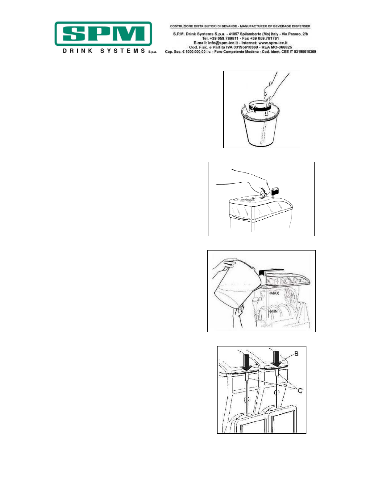
- Diluire e miscelare, in un recipiente a parte, lo
sciroppo con acqua secondo le indicazioni del
produttore (vedi figura 4); non versare mai
polveri secche, cristalli o sciroppo concentrato
direttamente nella vasca vuota.
!ATTENZIONE!
Accertarsi che la miscela abbia un contenuto di
zucchero compreso fra il 12.5% ed il 13.5%;
una minor concentrazione può seriamente
danneggiare gli organi miscelatori ed i motori
stessi.
NON USARE MAI SOLO ACQUA.
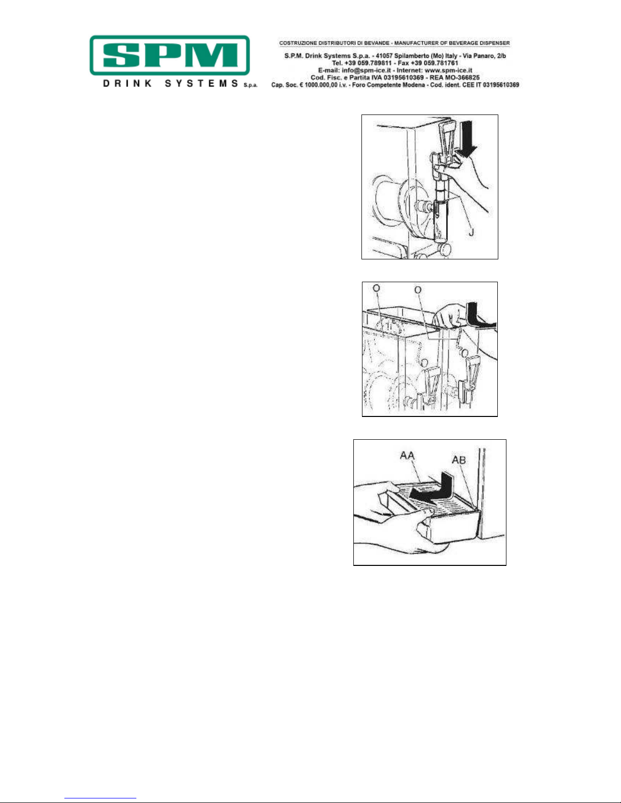
- Rimuovere il coperchio luminoso dopo averlo
sbloccato con l’apposita chiave (fig.5).
- Versare il prodotto ottenuto nella vasca (vedi
fig.6); sulla vasca sono riportati il livello
massimo e minimo di riempimento, non
riempire la vasca oltre il livello massimo e non
far funzionare la macchina sotto quello minimo.
Utilizzare la macchina con un livello di prodotto
al di sotto del livello minimo può danneggiare
l’apparecchio.
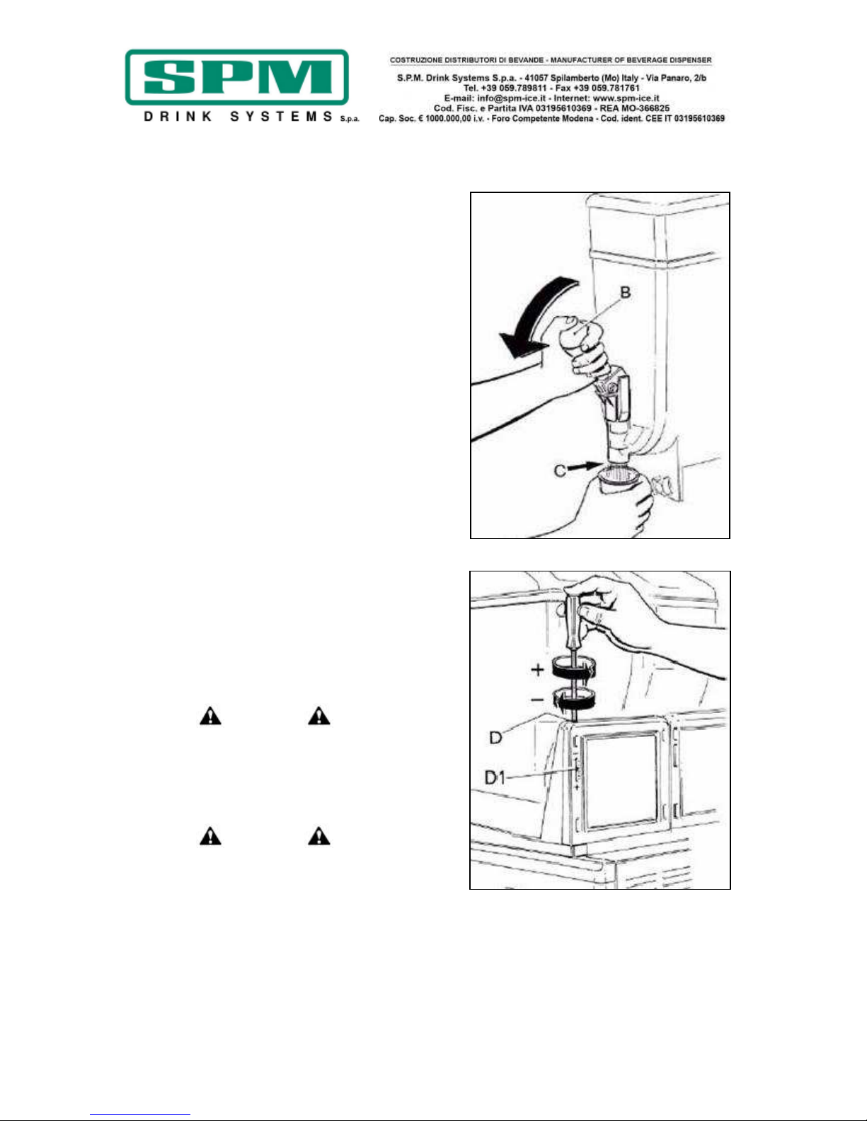
- Riposizionare il coperchio luminoso B avendo
cura che prema sul dispositivo di sicurezza C
(fig.7) e bloccarlo con l’apposita chiave.
Nota -----------------------------------------------
Ice Dream è dotata di un efficace dispositivo di
sicurezza, a tutela dell’operatore, che entra in
funzione con il sollevamento del coperchio e
determina l’automatico ed immediato arresto di
tutti gli organi in movimento.
Nel caso in cui il coperchio non sia
correttamente posizionato, la macchina
non entrerà quindi in funzione.
------------------------------------------------------
- Inserire la spina nella presa di alimentazione
elettrica ed attivare l’interruttore generale.
Fig. 4
Fig. 5
Fig. 6
Fig. 7
Page 9

Data di emissione: Aprile, 2011 Revisione: 1 Pag. : 9/124
Versione raffreddamento ad acqua
Per la versione raffreddata ad acqua sono valide
tutte le operazioni di avviamento descritte in
precedenza; oltre a queste è però necessario
collegare la macchina alla rete idrica come
descritto in seguito:
- Collegare la macchina alla rete idrica tramite il
tubo flessibile di carico acqua in dotazione,
munito degli opportuni raccordi da ¾.
!ATTENZIONE!
Si consiglia di interporre sempre un rubinetto
fra il tubo di carico e la rete idrica, tale rubinetto
deve essere sempre chiuso quando il granitore
non è utilizzato.
- Collegare la macchina ad un opportuno scarico
tramite il tubo flessibile retinato in dotazione,
avendo cura, dopo aver inserito l’estremità di
collegamento alla macchina nell’apposito porta
gomma, di fissare tale estremità con una
fascetta stringi - tubo.
NOTA: il consumo medio di acqua è di circa 1
litro al minuto.
In caso di mancanza acqua dalle rete idrica
durante il normale funzionamento, entra in
funzione il pressostato di sicurezza a riarmo
manuale e si accende la spia rossa posta sul
pannello comandi (Fig.8); la macchina
continua a funzionare con la sola esclusione del
compressore.
Dopo aver controllato la presenza dell’acqua
nella rete idrica, procedere con il riarmo del
pressostato di sicurezza posto sotto la macchina
verso il lato comandi premendo il tasto rosso
sporgente. Così facendo la spia rossa si
spegnerà ed il funzionamento del compressore
riprenderà normalmente.
Fig. 8
Page 10
Data di emissione: Aprile, 2011 Revisione: 1 Pag. : 10/124
9. SPIEGAZIONE DEGLI
INTERRUTTORI E RELATIVO USO
Versione meccanica
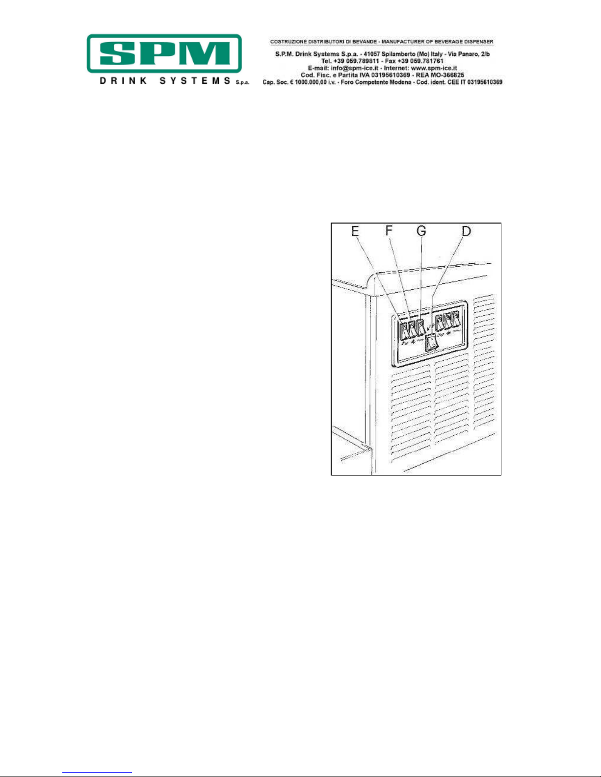
a) Attivare l’interruttore generale D (fig.9);
b) Ogni vasca è comandata da 3 interruttori che
azionerete come segue:
- per ottenere granita o sorbetto: selezionare
l’interruttore E per avviare gli organi miscelatori
(la contemporanea accensione del led verde,
collocato sull’interruttore, conferma l’avvenuta
selezione) e successivamente l’interruttore F per
azionare l’impianto frigorifero.
Nota: La macchina è dotata di un sistema di
ritardo per l’accensione dei compressori per cui
il led verde relativo all’interruttore F si
accenderà solamente dopo 4 minuti dalla sua
accensione.
- per ottenere bibita fredda: selezionare
l’interruttore E per avviare gli organi miscelatori
(la contemporanea accensione del led verde,
collocato sull’interruttore, conferma l’avvenuta
selezione) e successivamente, selezionare
l’interruttore G per azionare il sistema di
raffreddamento a temperatura positiva.
! Attenzione !
Gli interruttori F e G non devono mai
essere accesi contemporaneamente
! Attenzione !
Nel caso in cui la macchina venga spenta alla
sera, con le vasche piene, anche parzialmente,
si può verificare la formazione di uno strato di
ghiaccio solido in superficie, per effetto della
naturale separazione del prodotto non
mescolato. In tal caso, prima di riaccendere la
macchina è bene togliere questo strato di
ghiaccio superficiale onde evitare danni alla
coclea miscelatrice.
Fig. 9
Page 11
Data di emissione: Aprile, 2011 Revisione: 1 Pag. : 11/124
Solo per versione HC
!ATTENZIONE!
Le versioni HC sono munite di un pressostato di
sicurezza per l’impianto frigorifero, qualora la
temperatura interna della macchina dovesse
salire eccessivamente può accadere che tale
pressostato intervenga bloccando il
compressore.
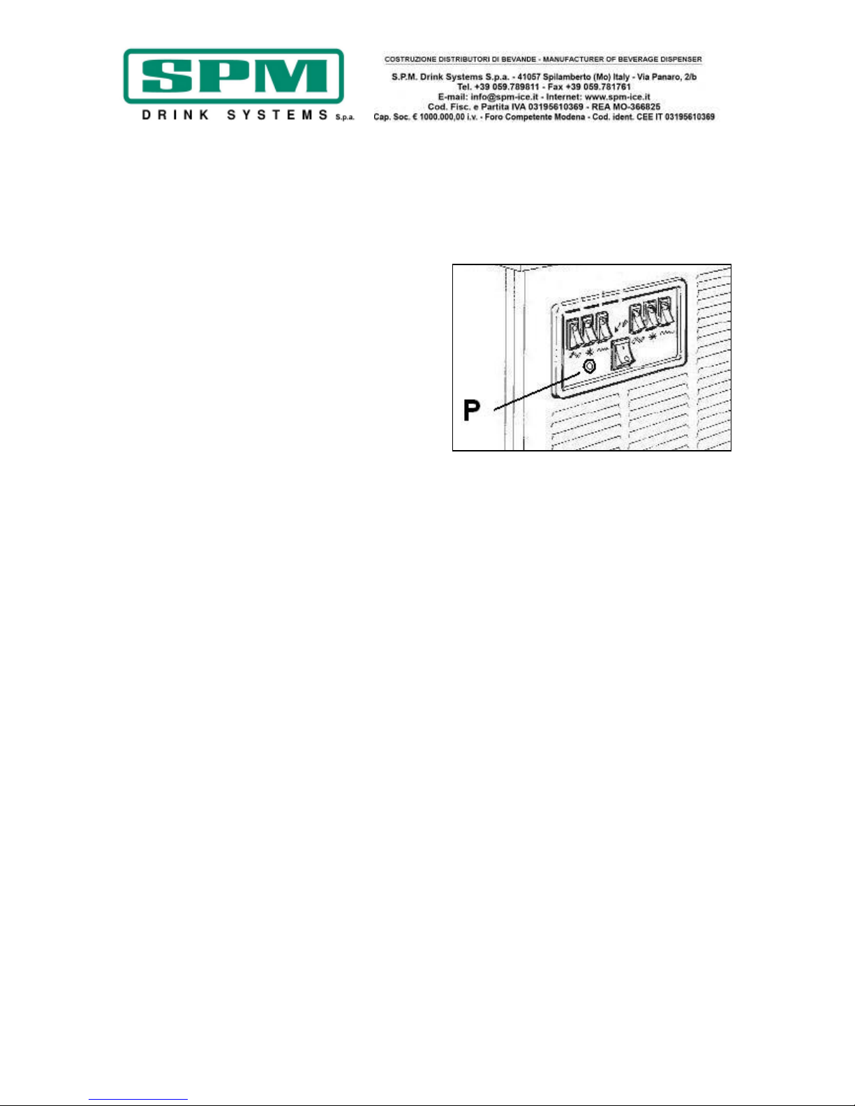
Qualora ciò dovesse accadere, la spia rossa P
sul pannello comandi (Fig.10) risulterà accesa e
l’impianto frigorifero risulterà bloccato.
Per ripristinare il normale funzionamento della
macchina sarà necessario individuare e risolvere
la cause di tale problema e, successivamente,
riarmare manualmente il pressostato premendo
il pulsante rosso posto al di sotto del granitore.
Le condizioni che possono causare questo
problema sono:
• Condizione :il condensatore è sporco e
necessita di essere pulito.
Azione correttiva : pulire accuratamente il
condensatore seguendo le istruzioni del capitolo
“manutenzione straordinaria”.
• Condizione: la macchina è posizionata troppo
vicino al muro o ad altri oggetti che riducono
l’aerazione.
Azione correttiva : aumentare la distanza da
tutti questi ostacoli in modo da favorire
l’aerazione come descritto in precedenza.
• Condizione: la macchina è stata posizionata
vicino ad una sorgente di calore.
Azione correttiva:riposizionare la macchina
lontano da fonti di calore.
Fig. 10
Page 12
Data di emissione: Aprile, 2011 Revisione: 1 Pag. : 12/124
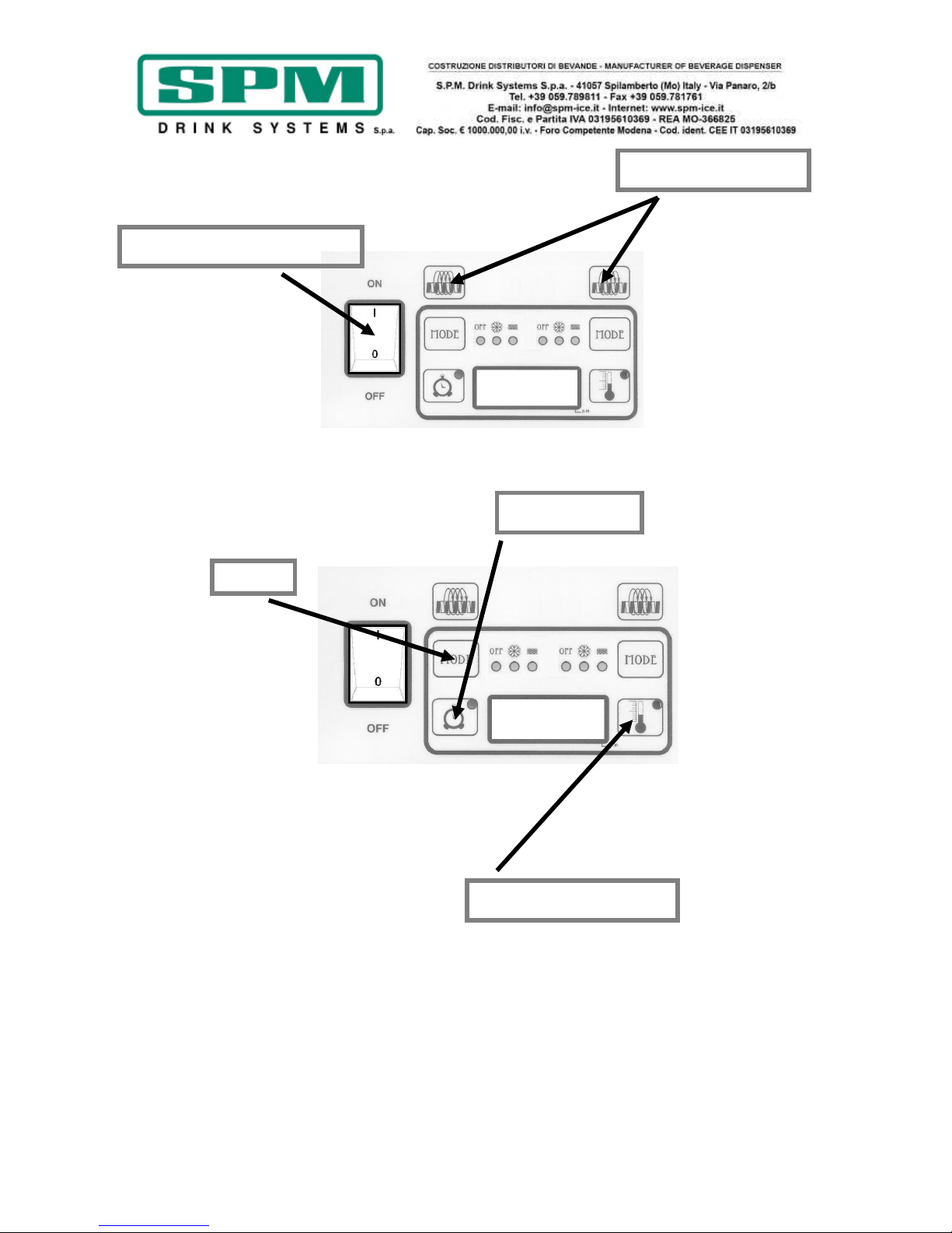
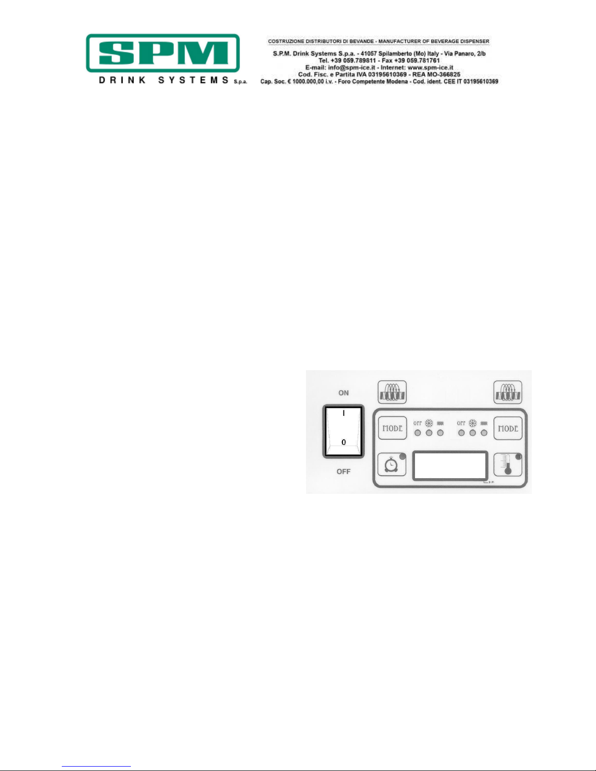
Versione PLUS elettronica
a)
Permette il
funzionamento della
macchina.
b) Permette, quando
attivato dopo aver
mantenuto premuto il
tasto “Agitatore ON/OFF” di sinistra, di
impostare le ore in 12 o 24 ore e la temperatura
in °F o °C.
c) Permette, quando attivato dopo aver
tenuto premuto il tasto “MODE” di sinistra, di
impostare l’orario.
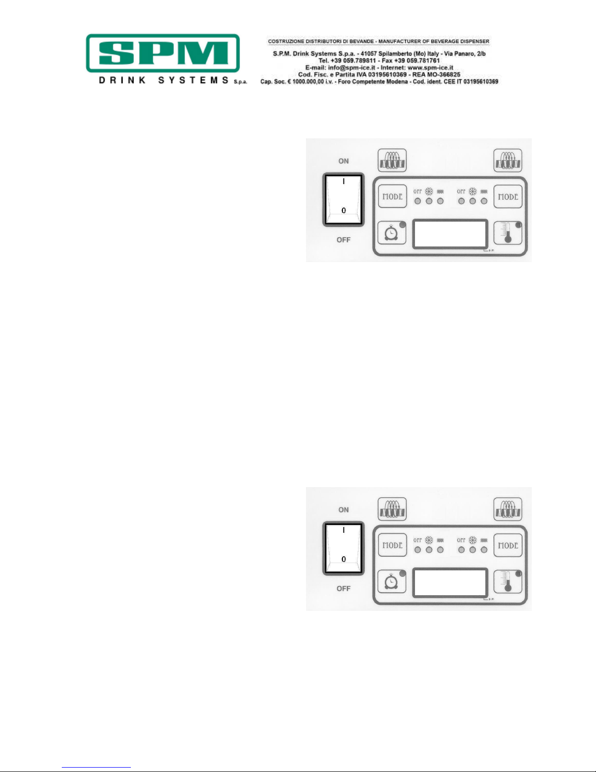
a) Permette la
selezione manuale delle
tre modalità di
funzionamento “OFF”,
“COOLING” o “FREEZING”
quando almeno uno degli
agitatori è attivo.
b) Permette la reimpostazione dei tempi di
decongelamento automatico quando mantenuto
premuto per 5 secondi con almeno uno degli
agitatori attivo.
c) Non funziona quando il LED sul tasto
“Auto timer” è acceso.
d) Permette la memorizzazione delle ore,
dei minuti e delle impostazioni finali dell’orario
dopo averle impostate con il tasto “Auto timer”.
Modalità di funzionamento:
OFF: la macchina non fa freddo;
COOLING: la macchina mantiene il prodotto
freddo ad una temperatura positiva;
FREEZING: la macchina produce granita.
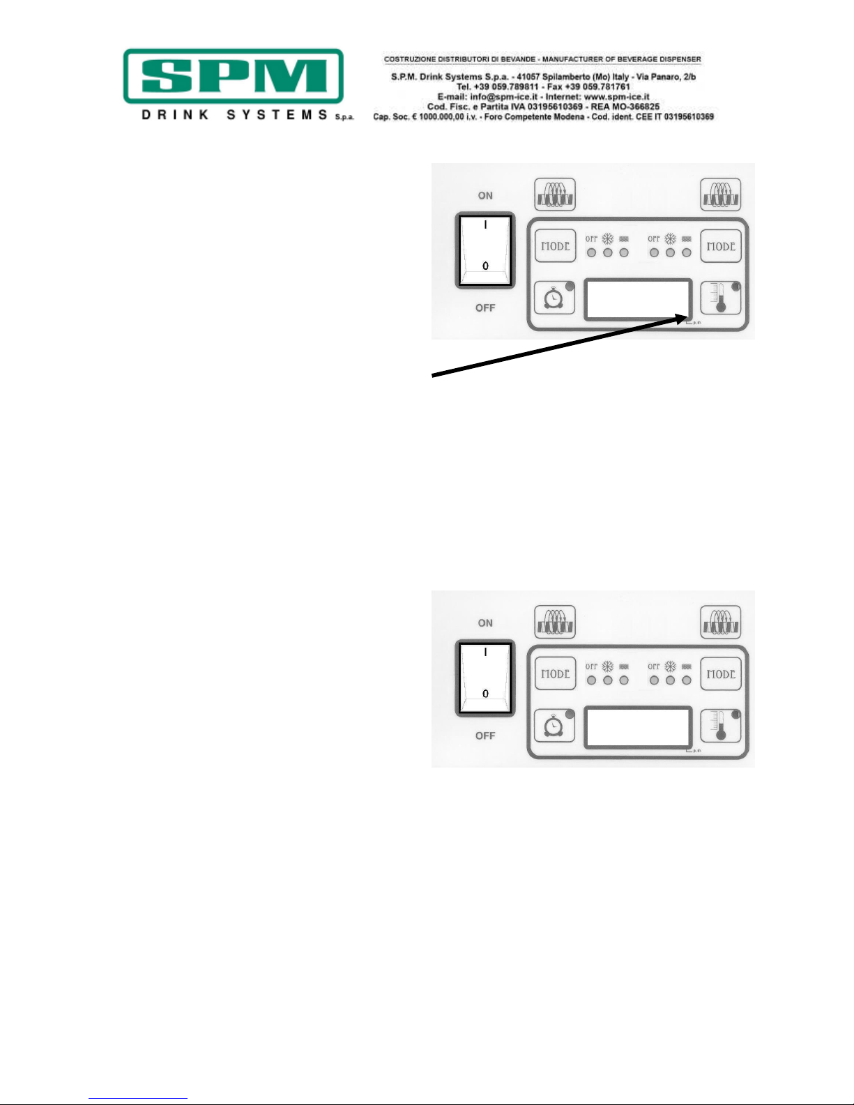
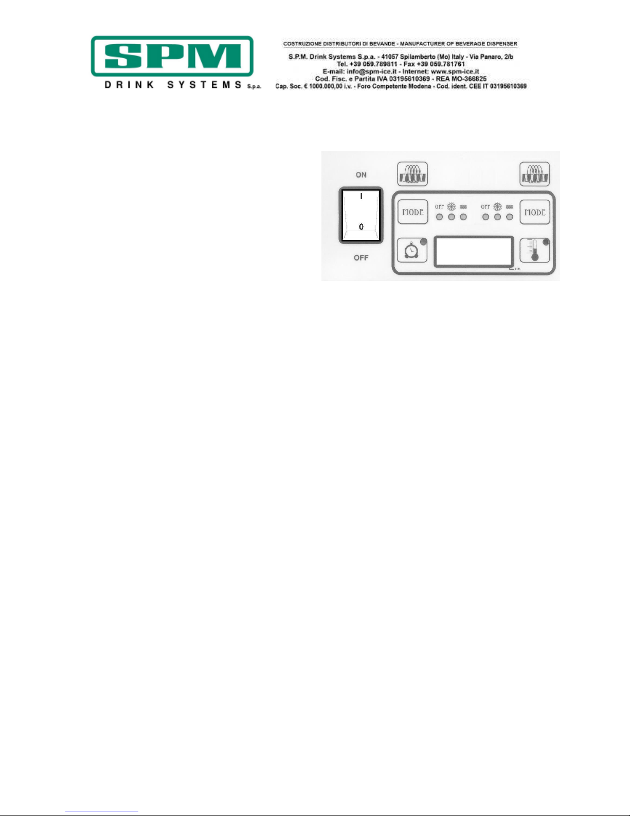
a) Permette di
attivare e disattivare gli
agitatori quando
l’interruttore principale è
acceso.
b)
Almeno uno dei
tre agitatori deve essere
attivo sia per poter
reimpostare i tempi di
decongelamento
automatico, sia per selezionare manualmente,
attraverso il tasto “MODE”, una fra le funzioni
“OFF”, ”FREEZING” o “COOLING”.
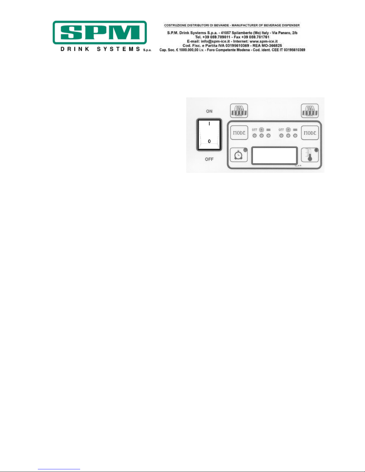
a) Modalità di defrost automatico:
LED acceso – attiva
LED spento - non
attiva.
b)
Permette di
variare le
regolazioni durante
le fasi di
reimpostazione.
c) RESET: mantenendo
premuto questo tasto quando si
attiva l’interruttore principale
vengono cancellate tutte le
impostazioni della macchina e
ripristinate quelle iniziali.
a)
In modalità “COOLING” premendo questo
tasto si legge in sequenza la temperatura del
prodotto:
LED1 = vasca sinistra;
LED2 = vasca centrale;
LED3 = vasca destra;
La lettura delle temperature delle vasche è
possibile solo con i relativi agitatori attivi.
NOTA:
LED termometro acceso - lettura in °F
LED termometro spento - lettura in °C
Agitatori
ON/OFF
Temperatura vasca
MODE
Interruttore principale
Auto Time
r
Page 13
Data di emissione: Aprile, 2011 Revisione: 1 Pag. : 13/124
Impostazione dell’orario
a) Spegnere l’interruttore principale.
b) Premere e tenere premuto il tasto
“MODE” di sinistra, attivare l’interruttore
principale e rilasciare il tasto “MODE” quando le
ore iniziano a lampeggiare.
c) Impostare l’orario usando il tasto “Auto
Timer” finché l’ora corretta non appare sul
display.
NOTA BENE: quando l’orario è espresso con
le 12 ore, se il LED nell’angolo in basso a
destra del display è acceso significa che è
pomeriggio, mattina invece se è spento.
d) Premere il tasto “MODE” di sinistra per
passare dall’impostazione delle ore a quella dei
minuti e regolarli come descritto in precedenza.
e) Premere Il tasto “MODE” di sinistra per
salvare l’orario impostato.
Impostazione orario di decongelamento
(funzionamento notturno)
a) Accendere l’interruttore principale,
assicurandosi che il tasto “Auto Timer” sia
spento.
b) Attivare almeno uno degli agitatori
premendo il relativo tasto “Agitatore ON/OFF”.
c) Premere e mantenere premuto il tasto
“MODE” di sinistra finché la macchina non
emette un lungo “beep” ed i LED, "COOLING"
ed "Auto Timer" iniziano a lampeggiare.
d) Premere il tasto “Auto Timer” per
impostare l’ora cui si vuol far partire la
modalità mantenimento prodotto (COOLING) e
successivamente premere il pulsante “MODE” di
sinistra per memorizzarla.
e) Premere il tasto “Auto Timer” per
impostare anche i minuti. In seguito premere il
tasto “MODE” di sinistra per salvare tale
impostazione. Fatte queste operazioni il LED
“COOLING” si spegnerà mentre inizieranno a
lampeggiare quelli di "FREEZING" e “Auto
Time”.
Page 14
Data di emissione: Aprile, 2011 Revisione: 1 Pag. : 14/124
f) Seguendo le stesse operazioni descritte
precedentemente si deve adesso impostare
l’orario cui si vuole che la macchina riprenda a
produrre la granita funzionando in modalità
“FREEZING”. Per concludere l’operazione
memorizzando anche questo orario è sufficiente
premere il tasto “MODE” di sinistra.
NOTA BENE: una volta che questi orari
sono stati impostati, la macchina li
mantiene automaticamente.
NOTA BENE: quando il LED sul pulsante
“Auto Timer” è acceso, le impostazioni di
decongelamento automatico sono attive ed
il tasto “MODE” di ciascuna vasca è inibito.
Per disattivare questa modalità di
funzionamento, premere il tasto "Auto
Timer" finché il suo LED non si spegne.
Funzionamento in automatico
(con le impostazioni di decongelamento
attive)
a) Attivare l’interruttore principale e
aspettare che si accenda il display.
b) Premere almeno uno dei tre tasti
"Agitatore ON/OFF".
c) Per far lavorare la macchina in
modalità decongelamento automatico premere
il bottone “Auto Timer” (LED relativo acceso).
NOTA BENE: I tempi del decongelamento
automatico sono gli stessi per tutte e tre le
vasche.
Page 15

Data di emissione: Aprile, 2011 Revisione: 1 Pag. : 15/124
Funzionamento in manuale
(senza le impostazioni di decongelamento
attive)
a) Attivare l’interruttore principale e
aspettare che si accenda il display.
b) Assicurarsi che il bottone “Auto
timer” sia spento (il LED ad esso relativo deve
essere spento).
c) Attivare le spirali con i relativi
tasti “Agitatore ON/OFF”.
NOTA BENE: almeno uno degli agitatori
deve essere attivato affinché la macchina
permetta di attivare una delle due modalità
di “COOLING” o di “FREEZING”.
d) Per ultimo selezionare la modalità
desiderata premendo il tasto “MODE” relativo
alla vasca di cui si vuote impostare il
funzionamento finché non si accende il LED
corrispondente.
NOTA BENE: in modalità “COOLING” di
mantenimento prodotto, il display mostra
la temperatura attuale del prodotto (la
temperature impostata non è modificabile).
Spingendo il pulsante con il termometro è
possibile vedere la temperature nelle tre
vasche a seconda che risulti acceso il LED 1
(vasca sinistra), il LED 2 (vasca centrale) o
il LED 3 (vasca destra).
Nelle modalità “OFF” e “FREEZING” il
display mostra l’orario.
Page 16
Data di emissione: Aprile, 2011 Revisione: 1 Pag. : 16/124
Impostazione della visualizzazione orario a
12 o a 24 ore e temperatura in °F o °C
a) Spegnere la macchina.
b) Premere il tasto "Agitatore
On/Off" di sinistra e, mantendolo premuto,
attivare l’interruttore principale. Rilasciare il
tasto "Agitatore On/Off" quando o 12 o 24
compaiono sul display indicando
l’impostazione attuale.
c) Premere il tasto “Auto Timer” fino
a quando compare l’impostazione desiderata
(12 o 24).
d) Premere il tasto “MODE” di
sinistra fino a quando non compare
l’impostazione corrente della temperatura (°F
o °C).
e) Premere il tasto “Auto Timer” fino
a quando compare l’impostazione desiderata
(°F o °C).
f) Memorizzare i cambiamenti spingendo il
tasto “MODE” di sinistra finché l’ora impostata
non appare.
g) Adesso la macchina è pronta per
essere utilizzata.
Visualizzazione della temperature
all’interno delle vasche
a) Premere il tasto “MODE” finché non si
accende il LED relativo alla modalità
“COOLING”.
b) Premere il tasto “Temperatura vasca“, in
sequenza si leggerà la temperatura del
prodotto relativo a:
LED1 = vasca sinistra;
LED2 = vasca centrale;
LED3 = vasca destra;
NOTA BENE: la lettura delle temperature
delle vasche è possibile solo con i relativi
agitatori attivi.
Page 17
Data di emissione: Aprile, 2011 Revisione: 1 Pag. : 17/124
Allarme di pulizia filtro “FILTER CLEANING”
L’allarme di pulizia filtro viene attivato quando
la temperatura interna della macchina diventa
troppo elevata. Quando questo succede la
scritta “Filt” compare sul display e un segnale
acustico intermittente allerta l’operatore.
Il messaggio “Filt” compare quando si attiva
l’allarme (un beep ogni 4-5 secondi).
Per definire le condizioni che hanno fatto
scattare questo allarme, vedere la lista
sottostante:
• Condizione A: il filtro è sporco ed è
necessario pulirlo.
Azione da intraprendere: pulire e
riposizionare il filtro seguendo le istruzioni
(Rimozione e pulizia del filtro).
• Condizione B: la macchina è posizionata
troppo vicino ad un muro o ad un altro
oggetto che ne limita il flusso d’aria forzando
così la macchina a lavorare a temperature
troppo alte.
Azione da intraprendere: modificare la
posizione della macchina in modo da
ottimizzare lo spazio per la ventilazione della
stessa (vedere le istruzioni di installazione).
• Condizione C: la macchina è stata
posizionata vicino ad una fonte di calore che
espelle aria calda forzando la macchina a
lavorare a temperature troppo elevate
(l’istallazione vicino a fonti di calore va
assolutamente evitata.
Azione da intraprendere: riposizionare la
macchina in modo da ottimizzarne la
ventilazione.
Page 18
Data di emissione: Aprile, 2011 Revisione: 1 Pag. : 18/124
Allarme di temperatura eccessiva
(surriscaldamento della macchina)
“SYSTEM OVER TEMPERATURE”
Quando la temperatura interna della macchina
arriva al valore limite impostato dalla casa
costruttrice, si attiva questo allarme come
precauzione di sicurezza onde evitare di
danneggiare il compressore.
• Il sistema va automaticamente in modalità
“OFF” dove il compressore è disattivato e
solo le spirali continuano a funzionare in
modo da evitare la formazione di blocchi di
ghiaccio.
• Quando ciò accade sul display compare la
scritta “Err” e la macchina inizia ad emettere
un suono continuo per mettere in allerta
l’operatore.
• Quando ciò accade è necessario spegnere
tutti gli interruttori e valutare le varie
possibili condizioni e le relative azioni da
intraprendere.
Page 19
Data di emissione: Aprile, 2011 Revisione: 1 Pag. : 19/124
10. MODALITA’ D’USO
a) Per erogare il prodotto, posizionare il
bicchiere sotto al rubinetto C e tirare la leva
B (vedi fig.11).
b) Regolazione della consistenza: per
variare la consistenza del prodotto, agire
sulla vite collocata nel retro della macchina
(fig. 12); girando in senso orario, il prodotto
diventerà meno denso, girando in senso
antiorario, il prodotto diventerà più denso.
Attenzione
Questo dispositivo agisce solo sulla consistenza
del prodotto da erogare (più o meno denso) e
non agisce assolutamente sulla temperatura di
raffreddamento dello stesso.
Attenzione
Quando il livello della granita all’interno della
vasca è sotto alla coclea miscelatrice, onde
evitare che il prodotto diventi troppo denso, è
necessario provvedere al rabbocco della vasca.
Fig. 11
Fig. 12
Page 20
Data di emissione: Aprile, 2011 Revisione: 1 Pag. : 20/124
11. OPERAZIONI DI PULIZIA E
SANITIZZAZIONE QUOTIDIANA
Al fine di avere sempre un buon funzionamento
dell’apparecchio e di rispettare le vigenti
normative sanitarie, è indispensabile effettuare
frequentemente e dettagliatamente le
operazioni di pulizia e sanitizzazione descritte in
seguito, assicurandosi sempre che la persona
adibita a tali operazioni, si sia in precedenza
lavata e sanitizzata le mani e gli avambracci.
Nel caso di prolungato inutilizzo dell’apparecchio
(stagionalità) eseguire sempre tali operazioni
prima di rimettere in funzione la macchina.
Attenzione
Onde evitare rischi di shock elettrico,
durante le operazioni di pulizia, non
spruzzare acqua sugli interruttori ed
evitare che i componenti elettrici interni
vengano a contatto con l’acqua ed i
prodotti utilizzati.
Attenzione
Per prevenire la formazione di batteri
usare solo prodotti approvati per la
disinfezione di oggetti in plastica e gomma,
il mancato rispetto di queste procedure
può provocare rischi alla salute.
NOTA BENE: è responsabilità dell’utilizzatore
essere consapevole delle normative vigenti in
modo da rispettare le leggi federali, statali o
locali, in termini di frequenza di pulizia e
conservazione dei prodotti utilizzati.
Le procedure descritte in seguito sono essenziali
per impedire la formazione di batteri e
mantenere così la macchina in ottime condizioni
igieniche.
Si consiglia di eseguire tali procedure
quotidianamente e comunque rispettando
sempre le normative in vigore.
Né la casa costruttrice della macchina, né il
quella produttrice del preparato alimentare
introdotto nella stessa, possono essere ritenute
responsabili per eventuali danni che possono
direttamente o indirettamente derivare a
persone in conseguenza della mancata
osservanza di tutte le prescrizioni indicate nel
presente manuale e concernenti specialmente le
avvertenze in tema di pulizia e sanitizzazione
dell’apparecchio.
Page 21
Data di emissione: Aprile, 2011 Revisione: 1 Pag. : 21/124
- Svuotare la vasca dal prodotto rimanente.
- Rimuovere il coperchio luminoso dopo averlo
sbloccato con l’apposita chiave.
- Riempire la vasca con acqua calda ma non
bollente in modo da facilitare lo scioglimento
dello zucchero residuo e poi svuotare tutta
l’acqua prima di procedure con il punto
successivo.
Attenzione
Onde evitare rischi di shock elettrico o di
contatto con parti mobili, durante le
operazioni di smontaggio e rimontaggio,
assicurarsi che tutti gli interruttori siano
nella posizione “off” e che il cavo di
alimentazione sia scollegato dalla rete.
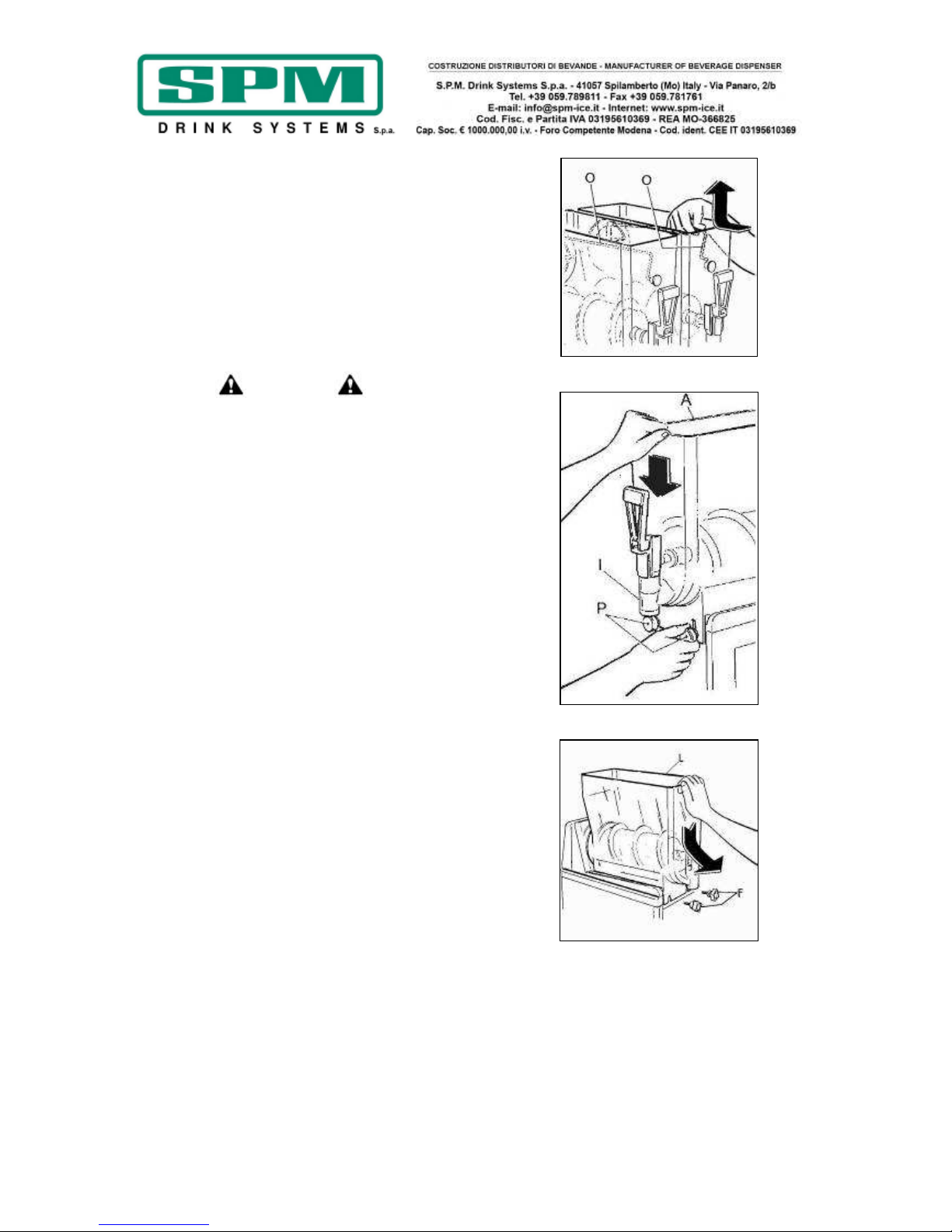
- Estrarre il dispositivo di miscelazione superiore
O spingendolo leggermente all’indietro per
poterlo disincastrare dalla propria sede (vedi
fig.13).
- Svitare e sfilare i pomelli P, abbassare la vasca
A al fine di eliminare eventuali residui di
prodotto attraverso il rubinetto di uscita I (vedi
fig.14).
- Tirare la vasca verso l’esterno, come
raffigurato, per poterla togliere totalmente dalla
propria sede (vedi fig.15).
Fig. 13
Fig. 14
Fig. 15
Page 22
Data di emissione: Aprile, 2011 Revisione: 1 Pag. : 22/124
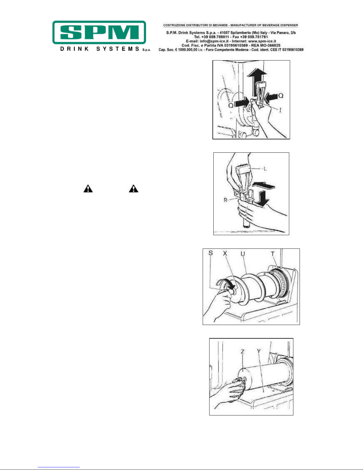
- Pulizia del rubinetto:
• Premere contemporaneamente sulle due
alette di blocco Q e sollevare il rubinetto
I per estrarlo dalla propria sede (vedi
fig.16).
• Smontare il rubinetto tenendo premuto
verso il basso il corpo R sfilando al leva L
dalla propria sede (vedi fig.17).
• Lavare accuratamente ogni singola parte
con acqua calda e detersivo per stoviglie,
risciacquare bene e procedere al
rimontaggio.
Attenzione
Per prevenire la formazione di batteri
rimuovere e pulire sempre anche gli o-ring;
il non rispetto di questa prescrizione può
provocare rischi alla salute delle persone.
- Svitare il pomello di fissaggio S nel senso della
freccia (filettatura sinistra) e procedere
all’estrazione del gruppo di miscelazione U e
delle guarnizioni di tenuta X e T (vedi fig.18).
!ATTENZIONE!
Evitare l’uso di detergenti abrasivi che
possono danneggiare la superficie dei
componenti. Non lavare tali componenti
nella lavastoviglie in quanto parti come la
vasca, le ruote dentate e la barra di
mescolamento superiore potrebbero venire
danneggiate.
- Lavare accuratamente ogni parte rimossa con
acqua calda e detergente per piatti delicato,
pulire bene anche il piano Y e l’evaporatore Z
(vedi fig.19). Risciacquare bene con acqua
pulita e lasciare asciugare. Rimontare il tutto
con le mani pulite.
Fig. 16
Fig. 17
Fig. 18
Fig. 19
Page 23

Data di emissione: Aprile, 2011 Revisione: 1 Pag. : 23/124
Una volta eseguite accuratamente tutte queste
operazioni di pulizia, si può procedere al
rimontaggio dei componenti.
Il corretto assemblaggio della macchina è molto
importante per prevenire perdite di prodotto ed
il danneggiamento della stessa.
Per assemblare la macchina è necessario
disporre di un lubrificante approvato (Vaselina).
Assicurarsi sempre che ogni parte sia stata
correttamente lavata e sanitizzata e che la
persona adibita al rimontaggio si sia
accuratamente lavato e sanitizzato le mani e gli
avambracci.
- Procedere al rimontaggio del gruppo di
miscelazione attenendosi alle seguenti
operazioni (vedi fig.20):
• È indispensabile spalmare la guarnizione
O con grasso di vaselina per ridurre l’attrito
e limitarne l’usura (fig.21).
• Rimontare la guarnizione P prestando
attenzione al verso (fig.22).
• Rimontare la spirale raschiante N avendo
cura che il codolo di trascinamento si incastri
perfettamente con l’albero di guida.
• Fissare tutti i componenti avvitando il
pomello M in senso antiorario.
- Rimontare la vasca A collocandola nella
propria sede accertandosi che faccia
esattamente tenuta con la guarnizione P (vedi
fig.23). Per agevolare il rimontaggio consigliamo
inoltre di inumidire la parte posteriore della
vasca nel punto in cui la stessa combacia con la
guarnizione di tenuta.
- Fissare la vasca A con gli appositi pomelli ed
avvitare saldamente, senza però esercitare una
forza eccessiva.
IMPORTANTE
Non serrare eccessivamente i pomelli di
fissaggio vasca, una forza eccessiva
potrebbe danneggiare la filettatura e/o la
vasca stessa.
Fig. 20
Fig. 21
Fig. 22
Fig. 23
Page 24
Data di emissione: Aprile, 2011 Revisione: 1 Pag. : 24/124
- Rimontare il rubinetto avendo cura di
cospargere con grasso di vaselina le guarnizioni
J per agevolare lo scorrimento del rubinetto
nella propria sede fino a completo inserimento
(vedi fig.24).
!ATTENZIONE!
Il non perfetto scorrimento del rubinetto
compromette la tenuta dello stesso.
- Procedere al rimontaggio del dispositivo di
miscelazione superiore O facendo in modo che
la sua corona dentata sia in fase con quella
inferiore facilitando così il perfetto incastro del
perno anteriore nella propria sede collocata sulla
vasca (vedi fig.25).
- Smontare la vaschetta raccogli - gocce AA
ruotandola leggermente verso l’alto e tirandola
verso l’esterno (vedi fig.26). Lavare
accuratamente ogni parte e procedere al
rimontaggio seguendo le operazioni sopracitate
al contrario ed avendo cura di reinserire il tubo
di scarico condensa AB nella propria sede.
- Collegare la macchina alla presa di corrente.
- Dopo aver rimontato tutti i componenti
riempire la vasca con una miscela di acqua e
sanitizzante (per esempio Amuchina), seguendo
le dosi ed i tempi specificati.
- Attivare i mescolatori in modo da sanitizzare
tutti i componenti seguendo le specifiche del
prodotto sanitizzante.
- Svuotare questa soluzione come descritto in
seguito:
• Rimuovere i due pomelli;
• Abbassare la vasca in modo da svuotarla
da ogni residuo di soluzione sanitizzante.
- Fissare di nuovo la vasca con i pomelli.
- Lavare la parte inferiore del coperchio con
acqua calda e detergente. Far asciugare in aria
e quindi pulire la superficie con un panno
imbevuto di soluzione sanitizzante.
!ATTENZIONE!
Il coperchio deve essere sconnesso dal suo
cavo di alimentazione, mai immergere il
coperchio in acqua o liquido.
Fig. 24
Fig. 25
Fig. 26
Page 25
Data di emissione: Aprile, 2011 Revisione: 1 Pag. : 25/124
12. MANUTENZIONE STRAORDINARIA
Attenzione
Prima di procedere a qualsiasi operazione
di manutenzione, è obbligatorio spegnere
l’apparecchio e staccare il cavo di
alimentazione dalla presa di corrente.
Pulizia filtro condensatore
Al fine di garantire un buon rendimento
dell’impianto frigorifero è indispensabile
effettuare periodicamente una la pulizia del filtro
del condensatore, procedendo come segue:
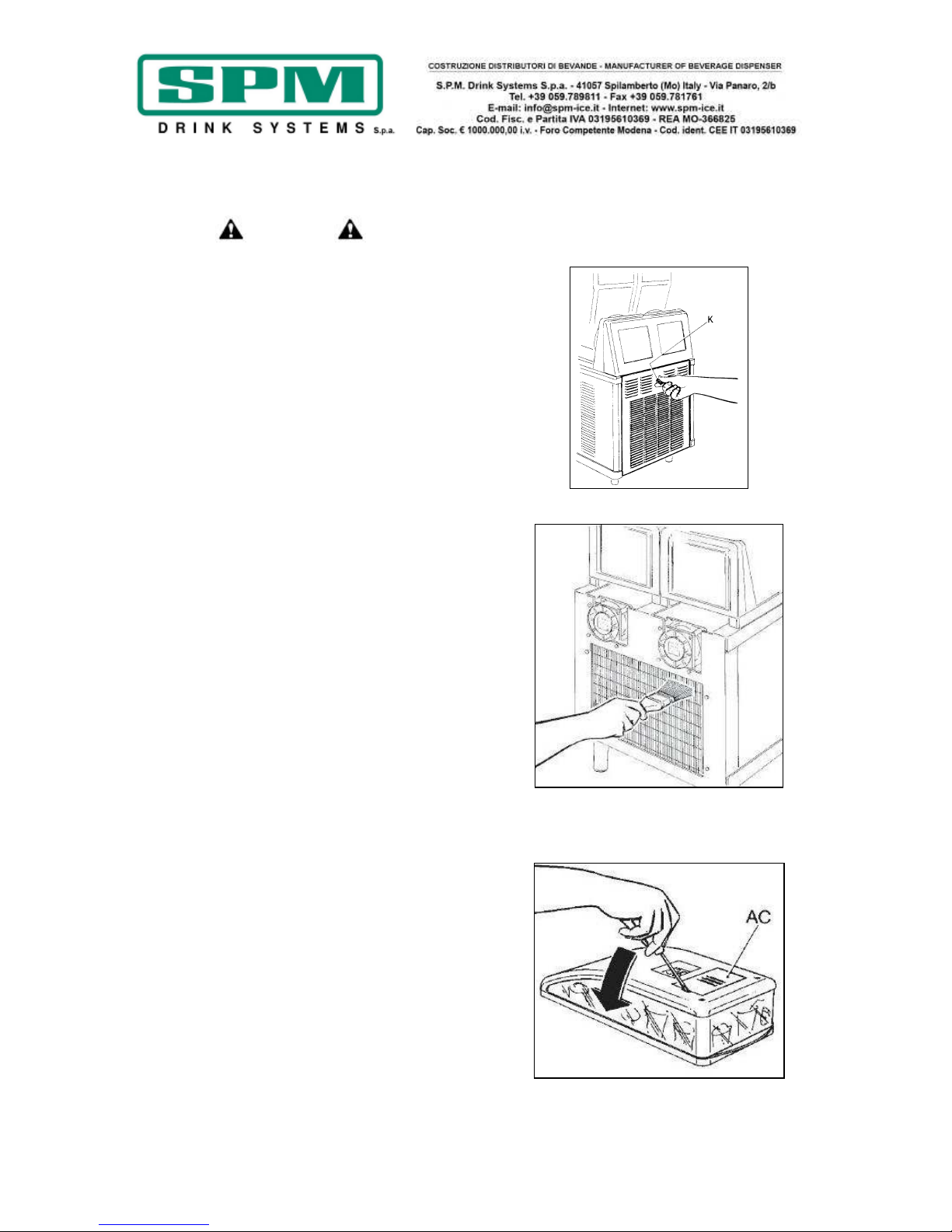
- Togliere la tensione all’apparecchio e
scollegare il cavo di alimentazione.
- Svitare il pomello K in modo da poter
rimuovere il pannello posteriore (vedi fig.27).
- Rimuovere la polvere infiltratasi fra le lamelle
del condensatore e pulire quest’ultimo con
acqua o con un aspirapolvere (vedi fig.28).
- Rimontare il pannello.
!ATTENZIONE!
Qualora il condensatore non venga
mantenuto pulito, ciò potrebbe causare
danni alla macchina ed annullare la
garanzia.
Sostituzione neon coperchio
- Per poter accedere alla lampada del coperchio
luminoso, fare leva sul coperchietto AC come
mostrato in figura 29.
- Rimuovere la lampada ed sostituirla con una
nuova.
- Richiudere e riposizionare il coperchio sulla
macchina.
- Inserire il suo cavo di alimentazione.
Fig. 27
Fig. 28
Fig. 29
Page 26

Data di emissione: Aprile, 2011 Revisione: 1 Pag. : 26/124
Controllo e sostituzione delle guarnizioni
GUARNIZIONE VASCA
La guarnizione posta sul retro della vasca va
sostituita ogni 12 mesi a seconda dello stato di
usura e del livello di manutenzione e
lubrificazione.
GUARNIZIONI (O-RING) RUBINETTO
Gli o-ring di tenuta del rubinetto di erogazione
prodotto vanno sostituiti ogni volta che
appaiono usurati. Queste guarnizioni vanno
lubrificate ogni volta che la macchina viene
rimontata dopo la pulizia e controllata
attentamente onde evitare perdite indesiderate.
GUARNIZIONE A VENTOSA
La guarnizione a ventosa posta sulla parte
frontale dell’evaporatore va sostituita ogni 3
mesi e comunque ogni volta che appare
usurata. Questa guarnizione va lubrificata con il
grasso di vaselina in dotazione ogni volta che
viene rimontata dopo la pulizia.
Stoccaggio invernale
Per proteggere la macchina durante i periodi di
inattività come l’inverno, è importante
sistemarla correttamente come descritto in
seguito:
- Disconnettere la macchina da qualsiasi fonte di
energia.
- Smontare, lavare e sanificare tutte le parti a
contatto con il prodotto (vedi capitolo 11).
- Pulire anche i pannelli esterni.
- Rimontare accuratamente tutti i componenti.
- Coprire la macchina completamente montata
con l’imballo originale in modo che venga
protetta dalla polvere e da altri agenti
contaminanti.
- Posizionare la macchina in un luogo asciutto.
13. ESCLUSIONE DI RESPONSABILITA’
La casa costruttrice declina ogni forma di
responsabilità per eventuali danni che possono
direttamente o indirettamente derivare a
persone, cose, animali in conseguenza della
mancata osservanza di tutte le prescrizioni
indicate nel presente manuale e concernenti
specialmente le avvertenze in tema di
istallazione, uso e manutenzione
dell’apparecchio.
Il produttore non risponde delle eventuali
inesattezze imputabili ad errori di stampa, di
trascrizione o di traduzione contenute nel
presente manuale; si riserva di apportare quelle
modifiche che ritenesse necessarie o utili, anche
nell’interesse dell’utilizzatore, senza
pregiudicare le caratteristiche essenziali di
funzionalità e sicurezza.
Page 27
Data di emissione: Aprile, 2011 Revisione: 1 Pag. : 27/124
14. GUIDA ALLA RISOLUZIONE DEI
PROBLEMI
NOTA BENE: le seguenti procedure devono essere eseguite da un tecnico qualificato
Problema Possibile causa Soluzione
La macchina non
raffredda o raffredda
solo parzialmente ed il
compressore funziona
• Lo spazio di ventilazione attorno
alla macchina è inadeguato
• La macchina sta funzionando in
modalità DEFROST
• Il condensatore è sporco e pieno di
polvere
• La ventola non sta funzionando
• C’è una perdita di refrigerante
• Lasciare almeno 20cm di spazio libero
attorno alla macchina e non posizionarla
vicino ad altre fonti di calore
• Ripristinare la modalità CONGELAMENTO
• Pulire il condensatore come descritto
• Controllare i collegamenti elettrici, se
disconnessi riconnettere e se ancora non
funziona, sostituire la ventola
• Individuare la perdita, eliminarla e
ricaricare l’impianto
La macchina non
raffredda o raffredda
solo parzialmente ed il
compressore non
funziona
• Le parti elettriche del compressore
non funzionano
• Alcuni collegamenti elettrici sono
incompleti
• Il compressore è difettoso
• Non arriva corrente alla scheda che
ritarda il compressore
• Sostituire i componenti che non
funzionano
• Verificare le connessioni e sistemare
quelle incomplete
• Sostituire il compressore
• Verificare i collegamenti elettrici alla
scheda ed al trasformatore che la
alimenta e correggere
La macchina raffredda
troppo rallentando o
bloccando la rotazione
della spirale
• Il grado zuccherino del prodotto è
troppo basso
• La vite di regolazione consistenza è
tarata ad un valore troppo alto
• La leva del micro-switch di durezza
è piegata ed non va a contatto con
il moto-riduttore
• Il livello del prodotto nella vasca è
troppo basso
• La scheda di ritardo del
compressore non apre i contatti
• Verificare il brix del prodotto e correggere
• Regolare la vite di durezza verso il “-“ per
ridurre la consistenza del prodotto
• Raddrizzare la leva con delle pinze e
ripristinare il corretto contatto
• Aggiungere prodotto o spegnere
l’impianto di refrigerazione
• Sostituire la scheda
La macchina è rumorosa • Le pale della ventola urtano alcuni
dei componenti interni
• Verificare e sistemare
L’interruttore principale
è in posizione ON ma la
macchina non funziona
• Il fusibile è bruciato
• Alcune connessioni elettriche sono
incomplete
• L’interruttore principale è rotto
• La scheda elettronica di comando è
difettosa
•
Il motoriduttore è difettoso
• Sostituire il fusibile
• Verificare le connessioni e sistemare
quelle incomplete
• Sostituire l’interruttore
• Sostituire la scheda comando
• Sostituire il motoriduttore
La vasca perde • Una delle guarnizioni non è
posizionata correttamente
• Rimontare correttamente la guarnizione
o, se è il caso, sostituirla
Il rubinetto perde • Il rubinetto non è stato rimontato
correttamente
• Il movimento del rubinetto è
impedito
• Gli o-ring di tenuta sono
danneggiati o usurati
• Smontare e rimontare correttamente il
rubinetto
• Pulire il rubinetto e la sua sede e
lubrificare con il grasso di vaselina in
dotazione
•
Sostituire gli o-ring
Il prodotto finisce nella
vaschetta raccogli gocce
attraverso il tubo di
drenaggio
• La guarnizione a ventosa, il mozzo
del mescolatore ed il pomello di
fissaggio non sono stati rimontati
correttamente
• La guarnizione a ventosa o la
boccola di tenuta dell’albero sono
danneggiati o usurati
• Smontare e rimontare correttamente il
sistema di mescolamento
• Smontare e sostituire le guarnizioni
Il mescolatore non gira • Alcune connessioni elettriche sono
incomplete
• La scheda elettronica è difettosa
•
Il motoriduttore è difettoso
• Verificare le connessioni e sistemare
quelle incomplete
• Sostituire la scheda
•
Sostituire il motoriduttore
Page 28

Data di emissione: Aprile, 2011 Revisione: 1 Pag. : 28/124
Problema Possibile causa Soluzione
Il mescolatore risulta
rumoroso durante la
rotazione
• La guarnizione a ventosa è stata
sostituita senza essere lubrificata
correttamente
• La spirale di mescolamento non è
stata rimontata correttamente
• Smontare, pulire, sanitizzare e lubrificare
correttamente la guarnizione
• Smontare e rimontare correttamente la
spirale e tutto il sistema di mescolamento
Sul display della scheda
appare uno dei seguenti
messaggi “Filt” o “Err”
• Il filtro è sporco e deve essere
pulito
• La macchina è posizionata troppo
vicino ad un muro o ad altri oggetti
che ne limitano il flusso d’aria di
raffreddamento facendo si che la
macchina lavori a temperature
troppo alte
• Il filtro non è montato
correttamente
• La macchina è stata posizionata
vicino ad altre fonti di calore che la
fanno lavorare a temperature
troppo elevate
• Smontare, pulire e rimontare il filtro
come descritto
• Riposizionare le macchina in modo da
massimizzare la ventilazione
• Installare correttamente il filtro
• Riposizionare le macchina in modo da
massimizzare la ventilazione
Il coperchio luminoso
non emette lacuna luce
• La lampada è bruciata
• Il trasformatore è bruciato
• I fusibile fra la lampada ed il
trasformatore è bruciato
• Sostituire la lampada
• Sostituire il trasformatore
• Sostituire il fusibile
Nelle versioni ad acqua:
la spia rossa sul
pannello comandi è
accesa
• La fornitura d’acqua nella rete
idrica è momentaneamente
sospesa
• Una volta ripristinata la fornitura d’acqua,
premere il pulsante rosso posto sotto la
macchina sul lato comandi in modo da
riarmare il pressostato di sicurezza
Nelle versioni HC: la
spia rossa sul pannello
comandi è accesa
•
Il condensatore è sporco e necessita
di essere pulito.
• La macchina è posizionata troppo
vicino al muro o ad altri oggetti che
riducono l’aerazione.
• La macchina è stata posizionata vicino
ad una sorgente di calore.
• Pulire accuratamente il condensatore
seguendo le istruzioni del capitolo
“manutenzione straordinaria” e riarmare
il termostato di sicurezza.
• Aumentare la distanza da tutti questi
ostacoli in modo da favorire l’aerazione
come descritto in precedenza e riarmare
il termostato di sicurezza.
• Riposizionare la macchina lontano da
fonti di calore e riarmare il termostato di
sicurezza.
Page 29

Data di emissione: Aprile, 2011 Revisione: 1 Pag. : 29/124
Published by:
SPM DRINK SYSTEMS S.p.a.
Via Panaro n° 2
41057 Spilamberto (MO)
Edition: 04/2011
Revision: 01
© 2011 – SPM Drink Systems
All copying rights are reserved to SPM DRINK SYSTEMS; copying, even partial, is illegal.
The descriptions and illustrations refer to the specific machine at issue. SPM Drink Systems reserves the right to
modify at any time the equipment for mass production.
This manual:
- is integral part of the supply and must be carefully read, in order to be properly used, in compliance with
the essential safety requirements;
- has been drafted by following the dispositions 2006/42/CE and reports the technical information that are
necessary to correctly run all the procedures, under safety conditions;
- must be carefully kept (protected by a transparent, watertight wrapping, in order to avoid any damage)
and must go with the machine during its life, including potential changes of ownership. In case of loss or
damage, it’s possible to ask for a copy to SPM DRINK SYSTEMS, pointing out the information stated on
the identification label;
SPM DRINK SYSTEMS declines all responsibility for a wrong usage of the machine and/or damages caused by
operations not provided for in this manual..
Dear Custom
er,
We would like to congratulate you for
choosing this high-quality product, that will
certainly meet all your expectations.
We thank you for the preference reserved to
our company and we invite you to carefully
read the following instruction manual before
machine’s start up.
Page 30

Data di emissione: Aprile, 2011 Revisione: 1 Pag. : 30/124
INDEX
1. IMPORTANT WARNINGS AND ADVICES
....................................................................31
2. EQUIPMENT KIT .......................................31
3. TRANPORT TIPS .......................................31
4. LIFTING TIPS .............................................31
5. TECHNICAL SPECIFICATIONS ..............32
6. POSITIONING ............................................33
7. CONNECTION TO THE POWER SUPPLY
MAINS .......................................................34
8. START-UP PROCEDURES .......................35
Water cooled system ....................................... 36
9. SWITCHES EXPLANATION AND THEIR
USES ..........................................................37
Mechanical version ......................................... 37
PLUS: electronic version ................................ 39
10. OPERATING INSTRUCTIONS .................46
11. DAILY CLEANING AND SANITIZING
PROCEDURES..........................................47
12. SPECIAL MAINTENTANCE.....................52
Condenser cleaning ......................................... 52
Luminous cover neon replacement ................. 52
Control and replacement of seals .................... 53
Winter storage ................................................. 53
13. DISCLAIMER .............................................53
14. TROUBLESHOOTING GUIDE .................54
15. WIRING DIAGRAMS ..............................112
Page 31

Data di emissione: Aprile, 2011 Revisione: 1 Pag. : 31/124
1. IMPORTANT WARNINGS AND
ADVICES
This installation and operation manual is
an integral part of the equipment and must
be kept for future consultation.
Unless otherwise stated, this manual is
addressed to operators (staff members
who uses the equipment on a daily basis)
and to servicemen (staff members qualified
to carry out the installation and/or
maintenance). The parts of the manual
addressed only to servicemen are pointed
out accordingly. Please read carefully the
warnings listed here below before
installation and start-up of the equipment.
This equipment has been designed to
produce slushes, sorbets and similar
products.
Upon receipt of the equipment, make sure
that its part number matches the one
specified in the order, which can be found
on all the delivery documents.
This equipment is exclusively destined to
the purpose for which it was designed. The
manufacturer cannot be held responsible
for any damage due to improper use.
This equipment is not intended for use by
persons (including children) with reduced
physical, sensory or mental capabilities, or
lack of experience and knowledge, without
supervision or instruction concerning its
use by a person responsible for their
safety. Children should be supervised to
ensure that they do not play with the
machine.
This equipment is not suitable for outdoor
use. This machine is not suitable for
installation in locations where water jets
are used. This equipment must be installed
in places where it can be controlled by
qualified staff.
2. EQUIPMENT KIT
In the packaging of this equipment you will find
also:
- operator’s manual,
- 1 tube of Vaseline grease lubricant to be used
for machine maintenance;
- EC declaration of conformity;
- 1 drip tray and 1 suction gasket for each bowl.
3. TRANPORT TIPS
To prevent the oil held in the hermetic
compressor running into the cooling circuit, the
device must be carried, stored and handled in
the upright position, following the direction
instructions on the packing. If the device is
accidentally or intentionally (for transportation
reasons) kept in any other position, it must be
set again in the correct position at least twenty
minutes before start-up procedures, in order to
let the oil flow back into the compressor.
4. LIFTING TIPS
Each machine is equipped with a special wooden
pallet that allows the handling with standard
forklift trucks.
Caution
Never lift the machine alone, but always seek
the assistance of another operator.
To prevent and avoid any damage to the
machine, all loading and unloading operations
should be carried out with special care. The
equipment can be lifted, with either a manual or
engine-powered lifting truck, by positioning the
forks in the base section of the unit.
The following operations should always be
avoided:
- to turn upside down the machine;
- to drag the machine with ropes or others;
- to lift the machine with slings or ropes
- to shake or rattle the machine and its
packaging.
Page 32

Data di emissione: Aprile, 2011 Revisione: 1 Pag. : 32/124
The machine must be stored in a dry place with
temperatures from 0°C to 40 °C. No more than
2 machines should be stacked on top of each
other, taking care to maintain the vertical
position, as shown by the arrows on the carton.
5. TECHNICAL SPECIFICATIONS
Technical and electrical specifications
All the machine’s technical and electrical
specifications are stated on the identification
plate, positioned in the internal part of the
equipment; a sample is shown here below.
The plate specifies:
• Model: XX
• n°: XX
• Electrical specifications: Volt/ Hz
• Max. absorption (Watt)
• Max. current (Amp)
• Machine ambient working temperatures
between 24°C and 32°C.
Dimensions and weight:
Ice Dream 1
• Height: 85 cm
• Width: 19.5 cm
• Depth: 56 cm
• Weight 40 kg
Ice Dream 2
• Height: 85 cm
• Width: 40 cm
• Depth: 56 cm
• Weight 60 kg
Ice Dream 3
• Height: 85 cm
• Width: 60 cm
• Depth: 56 cm
• Weight 100 kg
Noise emissions
The continuous, equivalent, weighted level of
acoustic pressure is below 70 dB.
In the event of breakdown:
In most cases, any technical problem can be
settled with slight interventions (please see the
troubleshooting guide at the end of this
manual); we therefore recommend you to
carefully read this handbook before contacting
the manufacturer or service centre.
Disposal
Caution
All the parts of the packaging must be kept
beyond the range of children, as they might
represent a potential safety/health risk.
Important
In respect of the environment, please dispose
the packaging as illustrated.
This symbol: means that the machine
cannot be disposed as common waste. It must
be handled in compliance with the provisions of
European directive 2003/108/CE (Waste
Electrical and Electronic Devices - WEEE) and
the resulting national legislation, in order to
prevent any potential damage to the
environment and to create health risks.
In order to correctly dispose of the device,
please contact the distributor from which you
purchased it or our after-sales service.
Page 33

Data di emissione: Aprile, 2011 Revisione: 1 Pag. : 33/124
6. POSITIONING
FOR SERVICEMAN ONLY
The installation and subsequent servicing
operations must be carried out by skilled
members who have been trained to use the
device and in compliance with the
regulations in force.
a) Remove the packing (fig.1), preserve it in
order to reuse for winter storage and make
sure the machine is in perfect condition.
!CAUTION!
All the parts of the packaging must be kept
beyond the range of children, as they
might represent a potential safety/health
risk.
b) Rest the machine on a sturdy, flat surface
making sure it is well ventilated by leaving a
gap of 20 cm around it and do not install it near
heat sources (fig.2); we recommend you to
maintain a room temperature between 24
and 32°C.
c) Check that the power mains voltage meets
the specifications on the equipment
identification plate and that the output available
meets the device’s power requirements.
Fit the plug into an earthed socket, removing all
multiple adaptors.
FOR FURTHER PRECAUTIONS, READ THE
SECTION “CONNECTION TO THE
ELECTRICITY MAINS” CAREFULLY.
d) The installation must be carried out in
accordance with the manufacturer’s instructions.
Failure to comply with the positioning and
installation instructions may impair the
machine’s operation.
Important
You are legally required to provide a suitable
grounding system for the equipment.
Before carrying out any cleaning and/or special
maintenance on the device, make sure it is
disconnected from the mains by unplugging it.
In the event of a breakdown or malfunctioning,
switch off the device and remove the plug.
Fig. 1
Fig. 2
Page 34

Data di emissione: Aprile, 2011 Revisione: 1 Pag. : 34/124
7. CONNECTION TO THE POWER
SUPPLY MAINS
FOR SERVICEMAN ONLY
Before fitting the plug in the power supply
socket, for your own safety, as already
mentioned in the previous paragraph, please
read the following precautions.
- The machine’s electrical safety is only
guaranteed when it is connected to a suitable
earth system, structured as provided by the
national safety current regulations (fig.3).
Therefore, the manufacturer cannot be held
responsible for any damage due to failure of the
grounding system of the machine.
- Do not obstruct the ventilating grill and heat
dispersion grill, since an insufficient ventilation
may not only reduce the efficiency of the
machine, causing it to function inadequately,
but may also cause serious damage to the
machine.
- Always verify electrical specifications on the
data plate of each machine. Data plate
specifications always replace the information of
this manual.
- For a safe and correct installation, it is
essential to provide a suitable socket controlled
by a thermal cut-out switch whose contacts are
at least 3 mm apart, in accordance with the
current national safety regulations (see fig.3).
- Never use extensions or multiple adaptors.
- Check the power lead along its entire length to
make sure it is not crushed in any way.
- To unplug the device, first disconnect the
power supply with the switch, then grip the plug
and gently pull it out.
Important
IF THE POWER CABLE IS DAMAGED, IT MUST
BE REPLACED BY THE MANUFACTURER, ITS
AFTER SALE SERVICE OR BY QUALIFIED
PERSONNEL, TO PREVENT ANY POSSIBLE RISK.
Fig. 3
Page 35

Data di emissione: Aprile, 2011 Revisione: 1 Pag. : 35/124
8. START-UP PROCEDURES
!IMPORTANT!
BEFORE STARTING THE MACHINE, CARRY OUT
THE CLEANING AND SANITISING PROCEDURES
DESCRIBED IN CHAPTER 11.
- Dilute and mix the product in a separate
container according to the manufacturer’s
instructions (see fig.4); never pour dry powder,
crystals, or concentrate into a dry bowl.
Caution
Make sure that the mixture has a sugar content
between 12.5% and 13.5%; a lower
concentration could seriously damage the
mixing parts, as well as the gearmotors.
NEVER USE ONLY WATER.
- Remove the luminous cover after unblocking it
by turning its special key clockwise (see fig.5).
- Pour the mix obtained into the bowl (see
fig.6); there is a minimum and maximum fill line
on the bowl, do not overfill or run the unit
without enough product. Running unit with
product below the minimum full line may cause
damage to the unit.
- Restore the luminous cover B making sure to
have it pushing against the security system C
(fig.7) and secure it with the special key.
Note -----------------------------------------------
Ice Dream is equipped with a very efficient
safety mechanism designed to protect the
operator; it is activated when cover is lifted.
This device automatically and immediately stops
all moving parts.
If the main cover is not correctly
positioned, the unit will not work.
------------------------------------------------------
- Insert the plug into the electrical power outlet.
- Activate the main switch.
Fig. 4
Fig. 5
Fig. 6
Fig. 7
Page 36

Data di emissione: Aprile, 2011 Revisione: 1 Pag. : 36/124
Water cooled system
In addition to these start-up procedures, only
for the water cooled version, it’s necessary to
connect the unit to the water main as described
below:
- Connect the unit to the water main with the
flexible filling pipe fitted with the ¾ connections.
!WARNING!
It is strongly recommended to interpose a tap
between the mains and the filling pipe; if the
unit is not working, this tap has to be closed.
- Connect the unit with a suitable draining
system by using the meshed pipe that you will
find together with the unit. After connecting this
pipe to the fastening junction under the frame,
remember to fix it with an hose clamp.
NOTE: the average of water consumption is
almost 1liter/minute.
In case of lack of water from the main during
the standard operating phase, the manual start
up safety pressure switch will block the unit and
the red LED on the switch panel will be switched
ON (fig.8); in this condition the machine is still
operating but the compressor is not working.
After checking the water presence in the main,
manually switch on the safety pressure switch
sited under the frame near the right side of the
unit by pressing the red jutting button.
After this operation, the red LED will be
switched off and the compressor will re-start
working normally.
Fig. 8
Page 37

Data di emissione: Aprile, 2011 Revisione: 1 Pag. : 37/124
9. SWITCHES EXPLANATION AND
THEIR USES
Mechanical version
a) Activate the general switch (D) (figure 9);
b) Each bowl is controlled by three switches
which are activated as follows:
- to make ice slush or sorbets: first select the
switch (E) to activate the mixer components
(the green LED on the switch will light up to
confirm the selection has been made), then
select the switch (F) to activate the cooling
system.
Note: the machine is equipped with a delay
system for the activation of the compressors, so
the green LED for the switch (F) will light up
only four minutes after it has been turned on.
- to make cold drinks: first select the switch (E)
to activate the mixer components (the green
LED on the switch will light up to confirm the
selection has been made), then select the
switch (G) to activate the cooling system at a
positive temperature.
! Warning !
Never turn all the switches F and G on at
the same time.
! Warning !
If the machine is turned off at night, with the
bowls filled, or just partially filled, a layer of
solid ice may form on the surface, due to the
natural separation of the unmixed product. In
this case, before turning the machine back on,
remove the layer of superficial ice, so as to
prevent damage to the mixing spiral.
Fig. 9
Page 38

Data di emissione: Aprile, 2011 Revisione: 1 Pag. : 38/124
Only for HC version
!WARNING!
HC units are equipped with a safety pressure
switch for the refrigerating system; if the unit
internal temperature would became too high the
pressure switch will block the compressor.
When the unit is running hot due to insufficient
internal air circulation and the pressure switch
blocks the compressor, the red LED on the
control panel is switched on (fig.10).
In order to restore the standard functioning, it
will be necessary to determine the condition
that caused the alarm and then to manually restart the compressor by pushing the red button
under the unit.
To determine the condition that caused the
alarm, see list of conditions below:
• Condition: The condenser is dirty and needs to
be cleaned.
Corrective Action: Clean the condenser following
instructions (Special maintenance).
• Condition: The unit is positioned too close to a
wall or other object restricting air flow and
causing the machine to run at a higher
temperature.
Corrective Action: Reposition unit to maximize
ventilation space (Positioning).
• Condition: The unit has been installed near a
heat source, such as a coffee machine, ice
maker or cold beverage machine which expels
hot air from its vents, causing the machine to
run at a high temperature (installation near a
heat source should be avoided)
Corrective Action: Reposition unit to maximize
ventilation space.
Fig. 10
Page 39

Data di emissione: Aprile, 2011 Revisione: 1 Pag. : 39/124
Bowl
temperature
PLUS: electronic version
a)
Turns unit ON.
b) Selects 12/24 time
and F°/C° temperature
display when turned ON
while simultaneously
pressing the auger button
(left one).
c) Sets current time when turned ON
while simultaneously pressing the “MODE”
button.
a) Used to manually
select “OFF”,
“FREEZING”, or
“COOLING” functions
when auger is turned ON
(one at least).
b) Accesses
automatic defrost timer reset mode when
pressed for a 5 seconds period when auger is
turned ON (one at least).
c) Does not function when light of “Auto
Timer” button is on.
d) Locks in hours, minutes and final time
settings after they are set using the “Auto
Timer” button.
Working mode:
OFF: the refrigerating system is not working.
COOLING: the machine is keeping the product
chilled.
FREEZING: the machine is producing slush.
a) Turns auger ON
and OFF when main
power switch is ON.
b) Must be ON (one
at leleast) to permit
defrost timer to be reset
and to activate the
“MODE” button to
manually select
“OFF”,”FREEZING”, or “COOLING” functions.
a) Turns auto
defrost mode ON or
OFF (light on switch
indicates when auto
defrost mode is
activated).
b)
Used to
change the settings
when readjusting
c) Permits to
reset the machine: press
and hold the “Auto timer”
button. Turn the main
switch ON and wait until
“PreS” appears on the
display.
a)
In the “COOLING” mode, the display will
read the actual temperature of the product:
LED1 on = left bowl
LED2 on = centre bowl
LED3 on = right bowl
To read the temperature the related auger has
to be active.
Thermometer LED on – Temperature in °F
Thermometer LED off – Temperature in °C
Auger ON/OFF
MODE
Main Power Switch
Auto Timer
Page 40

Data di emissione: Aprile, 2011 Revisione: 1 Pag. : 40/124
Enter Time Programming
a)
Turn the power switch OFF.
b) Press and hold the left “MODE” button
and turn the power switch ON. Release the
“MODE” button when the hour digits start
blinking.
c) Set the hour by pressing the “Auto
Timer” clock button until the appropriate hour is
shown.
NOTE: When using a 12 hour clock the time
is P.M. when the dot at the bottom right
corner of the LED display is lit; A.M. when
not.
d) Press the “MODE” button to set the
minutes and regulate them as described above.
e) Press the “MODE” button one more time
to save your settings.
Setting Defrost Timer (Night Setting)
a) Turn the power switch ON making sure
the “Auto Timer” is OFF.
b) Press the “Auger ON/OFF” button ON
(one at least).
c) Press and hold the left “MODE” button
until you hear a long beep and both the LED,
"COOLING" and "Auto Timer" begin to blink.
d) Press the “Auto Timer” button to set the
hour you want it to turn to refrigeration mode
(defrost mode) and then press the “MODE”
button to save the hour setting.
e) Press the “Auto Timer” button to set the
minutes. Then press the “MODE” button to save
also the minute setting. The “COOLING” light
will turn off while the "FREEZING" light and
“Auto Timer” one will begin blinking.
Page 41

Data di emissione: Aprile, 2011 Revisione: 1 Pag. : 41/124
f) Set the time you want the machine to
turn to FREEZING mode by following steps
above. Then press the left “MODE” button to
save also this time setting.
NOTE: Once the settings have been saved,
the unit will keep them.
NOTE: When the light on the “Auto Timer”
button is “ON”, the automatic defrost timer
is activated. To turn OFF this timer, press
the "Auto Timer" button (the light on the
clock button turns off).
Operate in Automatic Mode (with Defrost
Timer Activated)
a) Turn power switch ON and wait for
display to light up.
b) Press "Auger ON/OFF" buttons ON (one
at least).
c) To operate in defrost mode press the
“Auto Timer” button until it is illuminated.
NOTE: The defrost timer is the same for all
the bowls.
Page 42

Data di emissione: Aprile, 2011 Revisione: 1 Pag. : 42/124
Operate in Manual Mode (without Defrost
Timer Activated)
a) Turn the power switch ON and
wait for display to light up.
b) Make sure the clock button is OFF
(LED light on clock button should not be lit
up).
c) First turn auger on by pressing
the “Auger ON/OFF”
button.
NOTE: An auger (one at least) must be on
before the unit will allow the COOLING or
FREEZING mode to be activated.
d) Then select COOLING or
FREEZING mode by pressing the “MODE”
button until the light under the selection you
desire is lit up.
NOTE: In the COOLING mode, the LED
display will read the actual temperature of
the product (the temperature setting is not
adjustable). Pushing the thermometer
button it is possible to see the temperature
into the bowls: LED 1 – left bowl, LED 2 –
centre bowl and LED 3 - right one.
In the “FREEZING” or “Off” mode the LED
will read the current time.
Page 43

Data di emissione: Aprile, 2011 Revisione: 1 Pag. : 43/124
Setting the 12 or 24 Hour and the °F or °C
Temperature Display
a) Turn the power switch OFF.
b) Press and hold the left "Auger
On/Off" button and turn the power switch ON.
Release the "Auger On/Off" button when
either “12” or “24” are shown (indicates the
current hour view).
c) Press the “Auto Timer” button
until the desired hour display type is shown
(12 to 24).
d) Press the left “MODE” button until
the desired temperature display type is shown
(°F or °C).
e) Press the “Auto Timer” button
until the desired temperature display type is
shown (°F to °C).
f) Store the change by pressing the left
“MODE” button until the current time is
displayed.
g) The unit is now ready for use.
Viewing the Bowl Temperature
a) Press the left “MODE” button until the
“COOLING” LED is lit.
b) Press the “Bowl temperature “ button
choosing the bowl:
LED1 = left bowl:
LED2 = centre bowl;
LED3 = right bowl;
NOTE: to read the temperature inside the
bowls is possible only with their augers on.
Page 44

Data di emissione: Aprile, 2011 Revisione: 1 Pag. : 44/124
“FILTER CLEANING” Alarm
A filter cleaning alarm will activate when the
unit is running hot due to insufficient internal air
circulation. When this occurs a “Filt” message
will appear on the touch pad LED display
readout and an intermittent audible tone will
also sound to alert the operator of this
condition.
The “Filt” message will appear when the alarm
activates (a beeping sound every 4-5 seconds).
To determine the condition that caused the
alarm, see list of conditions below:
• Condition A: the filter is dirty and needs to
be cleaned.
Corrective Action: clean and replace filter
following instructions(Removing and
Cleaning Filter).
• Condition B: the unit is positioned too close
to a wall or other object restricting air flow
and causing the machine to run at a higher
temperature.
Corrective Action: reposition unit to
maximize ventilation space (Installation
Instructions).
• Condition C: the unit has been installed near
a heat source, causing the machine to run at
a high temperature (installation near a heat
source should be avoided).
Corrective Action: reposition unit to
maximize ventilation space.
Page 45

Data di emissione: Aprile, 2011 Revisione: 1 Pag. : 45/124
“SYSTEM OVER TEMPERATURE” alarm
A system over temperature alarm will activate
as a safety precaution when the unit has
overheated to protect the compressor.
• The system automatically goes to “OFF”
status where the compressor’s operations is
stopped, while augers will keep working to
avoid forming ice blocks.
• When this occurs an “Err” message will
appear on the touch pad LED readout
accompanied by a continuous buzzer sound
to alert the operator of this condition.
• When this alarm activates, turn off all
switches. Then determine the condition and
the necessary corrective action.
Page 46

Data di emissione: Aprile, 2011 Revisione: 1 Pag. : 46/124
10. OPERATING INSTRUCTIONS
a) To dispense the product, position the cup
under the tap (C) and pull the dispensing lever
(B) (see figure 11).
b) Adjusting the consistency: to alter the
consistency of the product, turn the screws
located on the back of the machine in the
following way: clockwise to make the product
less dense, anticlockwise to make the product
denser (see figure 12).
Important
This device only changes the consistency of the
product to be dispensed. It does not affect the
cooling temperature of the product.
Caution
When the level of the slush inside the bowl is
below the mixing spiral, to prevent the product
from becoming too thick, it is necessary to refill
the bowl.
Fig. 11
Fig. 12
Page 47

Data di emissione: Aprile, 2011 Revisione: 1 Pag. : 47/124
11. DAILY CLEANING AND SANITIZING
PROCEDURES
In order to maintain the machine in like-new
operating condition and to respect current
regulations, it’s absolutely necessary to
frequently and carefully perform the cleaning
and sanitizing operations as described below.
In case of prolonged shutdown (winter storage),
the machine must be disassembled, washed and
sanitized according to the instructions in this
manual before start-up to ensure the best
possible cleanliness.
Caution
Electric shock hazard. Do not splash water
on switches or allow water to flow onto
electrical components inside the machine.
Caution
To prevent bacteria growth, use only
sanitizers approved for plastic and rubber
objects, failure to do so could create a
health hazard.
NOTE: it is responsibility of the operator to be
aware of and conform to the requirements of
current local, state and federal laws concerning
the frequency of cleaning and conservation of
products used.
The cleaning instructions explained in this
section are essential procedures to remove
bacteria and maintain a sanitarily clean
machine.
We recommend to perform the cleaning
and sanitizing procedures every day and
anyway according to the local laws.
The machine and the mix manufacturers decline
all responsibility to damage that directly or
indirectly derives from people, animals, as
consequence of failure to comply with all
cleaning and sanitation instructions indicated in
this manual.
Page 48

Data di emissione: Aprile, 2011 Revisione: 1 Pag. : 48/124
- Empty the bowl of any remaining product.
- After unlocking the main cover with its key,
remove it.
- Fill the bowl with hot water (not boiling) to
help melt off any sugar residuals and drain this
water before proceeding with the next step.
Caution
To avoid electrical shock or contact with
moving parts, before proceeding with the
disassembling operations, make sure all
switches are in “OFF” position and that the
main power supply is disconnected.
- Pull out the upper mixing device (O) by
pushing it slightly backwards, to remove it from
its fixed position (see figure 13).
- Unscrew and slip off the knobs (P) then lower
the bowl (A) to eliminate any product residue
through the dispensing tap (I) (see fig. 14).
- Pull the tank outwards, as shown in the figure,
and remove it fully from its seating (see figure
15).
Fig. 13
Fig. 14
Fig. 15
Page 49

Data di emissione: Aprile, 2011 Revisione: 1 Pag. : 49/124
- Cleaning the dispensing tap:
• Simultaneously apply pressure to the two
securing tabs (Q), and lift the dispensing
tap (I) to pull it out of its fixed position
(see figure 16).
• Remove the dispensing tap by keeping
the indicated part (R) pressed down and
slipping off the dispensing lever (L) (see
figure 17).
• Thoroughly wash each single part with
hot water and mild dish washing
detergent, rinse well, and reassemble the
parts.
Caution
To prevent bacteria growth, remove all
o-rings when cleaning.
Failure to do so could create a health
hazard.
- Unscrew the securing bolt (S) in the direction
of the arrow (threading on the left), pull off of
the mixing unit (U), and remove the sealing
washers (X) and (T) (see figure 18).
!CAUTION!
Avoid the use of abrasive cleaners which
can damage the finish. Do not put the parts
in a dishwasher. Dishwasher may damage
some parts such as the clear plastic bowls,
auger gears, and top mixing bar.
- Thoroughly wash each single part that has
been removed in previous steps, and properly
base (Y), as well as the evaporator (Z) (see
figure 19) with hot water and mild dish washing
detergent. Rinse well with clear water and allow
to air dry. Reassemble with clean hands.
Fig. 16
Fig. 17
Fig. 18
Fig. 19
Page 50

Data di emissione: Aprile, 2011 Revisione: 1 Pag. : 50/124
Once performed all these cleaning and sanitizing
procedures, it’s possible to reassemble all the
components.
The correct assembly of the device is essential
to prevent leakage of product and damage of
the machine. To assemble the machine you will
need an approved lubricant (such as Vaseline).
Make sure all parts have been washed and
sanitized before assembling. Persons assembling
the machine must first wash and sanitize their
hands and forearms with an approved sanitizer.
- Mount the mixing unit back together,
according to the following procedures (see
figure 20):
• It’s indispensable to spread the gaskets
(O) with Vaseline grease to reduce
friction and thus limit wear (fig.21).
• Mount the bowl seal (P) making sure it
faces the right direction (fig.22).
• Replace the scraper auger (N), making
sure the head is perfectly engages with
the driving shaft.
• Secure all the parts into place by
screwing the bolt (M) in a counter
clockwise direction.
- Mount the bowl (A) back on, positioning it into
place, and making sure that it has a tight hold
on its washer (see figure 23). To facilitate this
procedure, we also suggest that the rear part of
the bowl be moistened at the point in which it
fits together with its sealing washers.
- Secure the bowl (A) by tightening the two
knobs, without exerting excessive pressure.
IMPORTANT
Do not over tighten the bowl knobs.
Excessive force could damage the thread
and/or the bowl itself.
Fig. 20
Fig. 21
Fig. 22
Fig. 23
Page 51

Data di emissione: Aprile, 2011 Revisione: 1 Pag. : 51/124
- Reassemble the parts of the dispensing tap,
making sure that the gaskets (J) are covered
with Vaseline grease so that the tap slides
smoothly back into its fixed position, until it’s
completely inserted (see figure 24).
!Important!
The not perfect sliding of the tap
compromises its own seal.
- Reassemble the upper mixing unit (O) so that
its toothed crown is aligned with the lower
crown. This will allow the front pin to fit
perfectly into its fixed position on the bowl (see
figure 25).
- Remove the liquid-collector tray (AA) turning it
slightly upwards and pulling it forward (see
figure 26). Wash each part thoroughly, then
reassemble the parts by inversely following the
procedures described above. Make sure that the
condensation drainage tube (AB) is reinserted
into its correct fixed position.
- Plug the unit back into appropriate power
supply.
- After the cleaning and reassembly as per
above instructions, fill the bowl with a mix of
water and an approved sanitizer (example Stera
Sheen), according to the measures specified.
- Start the mixing part of the machine to
sanitize all the parts following the cleaning
solution specifications.
- Drain the cleaning solution as follows:
• Unscrew the two knobs;
• Then lower the bowl to drain aou any
remaining product through the
dispensing valve.
- Screws the knobs to fix the bowls.
- With a clean cloth wash the underside of the
almp cover with warm water and mild
detergent. Allow this part to air dry and then
wipe it with a clean cloth which has been dipped
in the sanitizing mixture.
!ATTENTION!
Lamp cover must be unplugged, never
submerge lamp cover in water/liquid.
Fig. 24
Fig. 25
Fig. 26
Page 52

Data di emissione: Aprile, 2011 Revisione: 1 Pag. : 52/124
12. SPECIAL MAINTENTANCE
Caution
Before proceeding with any maintenance
operation, it is compulsory to switch off the
machine and unplug it from the mains.
Condenser cleaning
In order to guarantee good cooling system
performance, the condenser must be well
cleaned every month.
How to reach it:
- Switch off the power supply and disconnect
the power cable;
- Unscrew the knob (K) in order to remove the
back panel (see figure 27).
- Remove the dust inside the condenser fins and
clean it with a vacuum cleaner (fig.28).
- Restore the back panel.
!ATTENTION!
Failure to maintain a clean filter and
condenser will cause damage to the unit
and consequently void the warranty.
Luminous cover neon replacement
Replace the neon of the luminous cover,
according to the following procedures:
- Remove the small plastic cover AC as indicated
(fig.29).
- Carefully remove the lamp and replace it with
a new one.
- Reassemble the small cover AC.
- Place lid on machine and plug lid cord back
into lid.
Fig. 27
Fig. 28
Fig. 29
Page 53

Data di emissione: Aprile, 2011 Revisione: 1 Pag. : 53/124
Control and replacement of seals
BOWL GASKET (LOCATED AT THE REAR OF
BOWL)
Replace it every 12 months according to the
conditions of use and level of maintenance.
DISPENSE VALVE O-RING
The dispense valve o-rings should be replaced
as necessary when wear is evident. Lubricate
them each time they are replaced or the
dispense valve is removed for cleaning.
SUCTION GASKET
Replace every 3 months according to the
conditions of use and level of maintenance. This
part should be lubricated during the reassembly after every cleaning with Vaseline.
Winter storage
To protect the unit during seasonal shutdown,
it’s important to properly store the machine
using the following procedures:
- Disconnect all power to the freezer.
- Disassemble, wash and sanitize all parts that
come into contact with the mix as described in
chapter 11.
- Clean also all the exterior panels.
- Reassemble all these parts.
- Cover the machine with the original package
to protect it from dust or other contaminating
elements.
- Place the machine in dry location.
13. DISCLAIMER
The manufacturer declines all responsibility for
any damage that directly or indirectly might be
brought on to people, things, animals, as a
consequence of failure to comply with all
instructions given in this manual with the
warnings concerning installation procedures, use
and maintenance of the machine.
The manufacturer cannot be held responsible for
possible mistakes due to printing, copying or
translating errors contained in this manual.
In addition, the manufacturer reserves the right
to modify what deemed necessary or useful for
the machine, as well as for the benefit of the
user, yet at the same time maintaining the
essential operative and safety characteristics of
said machine.
Page 54

Ausgabedatum: Aprile, 2011 Revision: 1 Seite: 54/124
14. TROUBLESHOOTING GUIDE
Problem Possible cause Solution
The machine does not cool,
or cools only partially and
the compressor is running
• The space around the machine is
inadequate for ventilation
• The refrigeration system is working in
DEFROST mode
• The condenser filter is clogged with
airborne particles
• Fan motor is not running
• Refrigerant is leaking
• Allow at least 20cm between the
machine and anything next to it;
keep it away from heat sources
• Return to FREEZE mode
• Clean the filter
• Check the fan motor’s electrical
connections and, if disconnected,
reconnect. If still not operating,
replace the motor
• Locate the leak, eliminate it and
recharge the system
The machine does not cool,
or cools only partially and
the compressor is not
running
• Electrical components of the compressor
are not functioning
• Some electrical connections are not
complete
• The compressor is malfunctioning
• No current is coming to the “compressor
delay” mother board
• Replace the malfunctioning
components
• Check the contacts and correct
those incomplete
• Replace the compressor
• Check the electrical connections
to the pc board as well as the
transformer feeding the PC
board and correct
The machine over-freeze,
making the auger movement
slow or stopped
• The product brix is too low
• The screw setting for the consistency
control system is set too far toward the
“+” position
• The limit micro-switch arm is bent away
from the gear motor and prevents
contact
• The level of the product in the bowl is
too low
• The compressor PC board contact don’t
open
• Check the product brix and
correct
• Reset the screw toward the “-“
position to produce a thinner
consistency product
• Using pliers, straighten the limit
switch arm
• Add more product or turn the
refrigeration “Off”
• Replace the PC board
The machine is noisy • The fan motor blades are hitting internal
components
• Check and correct
The main power switch is
“ON” but the unit s not
running
• The fuses are blown
• Some electrical connections are not
complete
• The main power switch is broken
• The control board is faulty
•
The gear motor is malfunctioning
• Replace the fuses
• Check the contacts and correct
those incomplete
• Replace the switch
• Replace the control board
•
Replace the gear motor
The bowl is leaking
•
One of the bowl seal is not in place
•
Replace or reposition the seal
The dispensing valve is
leaking
• The dispensing valve has been
incompletely or incorrectly replaced in its
position
• The free movement of the valve is
impeded
•
Dispensing valve o-rings are damaged
• Reassemble and replace
• Clean and lubricate the valve
and the valve cylinder with the
lubricant provided with the
machine
•
Replace the o-rings
Product is flowing into drain
tray through drainage pipe
• The bell shaped seal between the front of
the cylinder and the auger hub has not
been reinstalled properly
• The bell shaped shaft seal or the spindle
bushing seal is damaged or worn
• Find the seal and put it back in
place
• Replace the damaged/worn seal
and check the condition of the
drive shaft
The auger is not turning • Some electrical connections are not
complete
• The control board is faulty
•
The gear motor is malfunctioning
• Check the contacts and correct
those incomplete
• Replace the control board
•
Replace the gear motor
NOTE: the following procedures
must be performed by a
qualified service technician.
Page 55

Ausgabedatum: Aprile, 2011 Revision: 1 Seite: 55/124
The auger is creating noise
as it rotates
• The bell shaped shaft seal has been
replaced without lubrication or is
damaged
• The auger has been incompletely or
incorrectly reassembled
• Replace or clean and lubricate
with the lubricant provided with
the machine
• Check and correct
“Filt” or “Err” message
appears on the touchpad
LED readout
• The filter is dirty and needs to be
cleaned
• The unit is positioned too close to a wall
or other object restricting air flow and
forcing the machine to run at a higher
temperature
• The filter is not properly installed
• The unit has been installed near a heat
source, such as a coffee machine, ice
maker or cold beverage machine which
expels hot air from its vents, forcing the
machine to run at a high temperature.
• Clean and replace filter following
instructions
• Reposition unit to maximize
ventilation space (see
installation figures)
• Install properly the filter
• Reposition unit to maximize
ventilation space (see
installation figures)
There is no light in the
merchandising lid
• The neon is burnt out
• The transformer is blown
• The 5 Amp fuse between the transformer
and the lamp is blown
• Replace the neon
• Replace
• Replace
Only for water cooled
versions: the red LED on the
control panel is ON
• The water supply from the main is
temporary suspended
• Once the water supply has been
restored, push the red button
under the frame in order to re-
start the compressor
Only for HC versions: the red
LED on the control panel is
ON
• The condenser is dirty and needs to be
cleaned.
• The unit is positioned too close to a wall
or other object restricting air flow and
forcing the machine to run at a higher
temperature.
• The unit has been installed near a heat
source, such as a coffee machine, ice
maker or cold beverage machine which
expels hot air from its vents, forcing the
machine to run at a high temperature
• Clean the condenser
• Reposition unit to maximize
ventilation space
• Reposition unit to maximize
ventilation space
Page 56

Ausgabedatum: Aprile, 2011 Revision: 1 Seite: 56/124
Herausgeber der Veröffentlichung:
SPM DRINK SYSTEMS S.p.A.
Via Panaro 2
41057 Spilamberto (MO)
Ausgabe: 04/2011
Stand: 01
© 2011 – SPM Drink Systems
Alle Rechte vorbehalten. Der Nachdruck, auch auszugsweise, ohne Genehmigung seitens SPM DRINK SYSTEMS ist
untersagt.
Die Beschreibungen und Abbildungen beziehen sich auf die spezifische in diesem Handbuch behandelte
Maschine/Anlage. SPM DRINK SYSTEMS behält sich vor, jederzeit alle für die Serienproduktion als notwendig
erachteten Änderungen vorzunehmen.
Die vorliegende Anleitung:
ist wesentlicher Bestandteil der Lieferung und muss in Entsprechung der grundlegenden
Sicherheitsvorschriften vor dem Gebrauch aufmerksam durchgelesen werden;
wurde laut Bestimmungen der Maschinenrichtlinie 2006/42/CE ausgearbeitet und enthält die
erforderlichen technischen Informationen für die korrekte Ausführung aller Verfahren unter Sicherheitsbedingungen;
muss sorgfältig in einem wasser- und staubdichten transparenten Umschlag aufbewahrt werden und die
Maschine während ihrer gesamten Nutzzeit, auch im Fall eines Besitzerwechsels, immer begleiten. Bei
Verlust oder Beschädigung des Handbuchs können Sie unter Angabe der Daten auf dem Typenschild bei
SPM DRINK SYSTEMS ein Ersatzexemplar anfordern.
SPM DRINK SYSTEMS übernimmt keine Verantwortung für einen unsachgemäßen Gebrauch der Maschine/Anlage
und/oder für Schäden, die durch eine bestimmungsfremde nicht in dieser Anleitung vorgesehene Nutzung entstehen
sollten.
Sehr geehrte Kundin, sehr geehrter Kunde,
wir beglückwünschen Sie zur Wahl eines
Qualitätserzeugnisses und sind sicher, dass
es Ihre Erwartungen erfüllen wird.
Wir danken Ihnen, uns den Vorzug gegeben
zu haben und bitten Sie, die vorliegende
Gebrauchs- und Wartungsanleitung
aufmerksam durchzulesen.
Page 57

Ausgabedatum: Aprile, 2011 Revision: 1 Seite: 57/124
INHALT
1. WICHTIGE ANWEISUNGEN UND
HINWEISE ................................................58
2. AUSSTATTUNG DES GERÄTES .............58
3. NÜTZLICHE TRANSPORTHINWEISE ...58
4. NÜTZLICHE INFORMATIONEN ZUM
ANHEBEN ................................................58
5. TECHNISCHE SPEZIFIKATIONEN .........59
6. AUFSTELLUNG .........................................60
7. ELEKTRISCHER ANSCHLUSS ................61
8. INBETRIEBNAHME ..................................62
Wassergekühlte Ausführung ........................... 63
9. ERKLÄRUNG DER SCHALTER UND
IHRES GEBRAUCHS ...............................64
Mechanische Ausführung ............................... 64
Elektronische Ausführung PLUS .................... 66
10. GEBRAUCH................................................73
11. TÄGLICHE REINIGUNG UND
DESINFEKTION .......................................74
12. AUSSERGEWÖHNLICHE WARTUNG ...79
Reinigung des Kondensatorfilters ................... 79
Austausch der Neonlampe des Deckels .......... 79
Überprüfung und Ersatz der Dichtungen ........ 80
Winterlagerung ............................................... 80
13. HAFTUNGSAUSSCHLUSS .......................81
14. FEHLERSUCHE UND ................................82
Page 58

Ausgabedatum: Aprile, 2011 Revision: 1 Seite: 58/124
1. WICHTIGE ANWEISUNGEN UND
HINWEISE
Die vorliegende Gebrauchs- und
Wartungsanleitung ist wesentlicher
Bestandteil des Produktes und ist als
Unterlage gut aufzubewahren. Soweit nicht
anders angegeben, richtet sich das
vorliegende Handbuch an den Anwender
(Personal, das das Gerät täglich benutzt)
und an das Wartungspersonal (qualifizierte
Installateure und/oder
Wartungstechniker). Die nur für den
Wartungstechniker bestimmten Abschnitte
sind entsprechend gekennzeichnet. Lesen
Sie die Anweisungen des vorliegenden
Handbuches vor dem Gebrauch und der
Installation des Gerätes aufmerksam durch.
Das Gerät ist für die Herstellung von
Granita, Sorbett und ähnlichen Produkten
aus Wasser oder Milch und Fruchtsirup
bestimmt.
Kontrollieren Sie beim Empfang des
Gerätes, dass die Bestellnummer desselben
der Ihrer Bestellung entspricht,
die immer auf den Versandpapieren
angegeben ist, d.h.:
- "Gerätename" gefolgt von der
fortlaufenden Seriennummer.
Dieses Gerät ist ausschließlich für den
Zweck bestimmt, für den es konzipiert
wurde. Der Hersteller haftet nicht für
eventuelle Schäden durch unsachgemäßen
Gebrauch.
Das vorliegende Gerät ist nicht für die
Benutzung durch Kinder oder Personen
vorgesehen, die in ihrer psychischen oder
motorischen Leistungsfähigkeit
beeinträchtigt sind oder denen es an
Erfahrung oder Kenntnissen mangelt, es
sei denn, sie werden von einer für ihre
Sicherheit verantwortlichen Person
beaufsichtigt oder in die Benutzung des
Gerätes eingewiesen. Kinder sollten
beaufsichtigt werden, um sicherzustellen,
dass sie nicht mit dem Gerät spielen.
Das vorliegende Gerät ist nicht für den
Einsatz im Freien geeignet. Das
vorliegende Gerät darf nicht an Orten
installiert werden, an denen
Wasserstrahlen verwendet werden. Das
vorliegende Gerät muss an Orten installiert
werden, an denen es durch qualifiziertes
Personal überwacht werden kann.
2. AUSSTATTUNG DES GERÄTES
In der Ihnen ausgelieferten Verpackung finden
Sie:
- Die vorliegende Gebrauchs- und
Wartungsanleitung;
- die CE-Konformitätserklärung;
- 1 Tube Schmierfett (Vaseline)
- 1 Abtropfschale und 1 Saugdichtung für jeden
Behälter.
3. NÜTZLICHE TRANSPORTHINWEISE
Um zu verhindern, dass das Öl aus dem
hermetischen Kompressor in den Kältekreislauf
fließt, darf das Gerät laut Angaben auf der
Verpackung nur in senkrechter Position
transportiert, gelagert und gehandhabt werden.
Falls das Gerät versehentlich oder beim
Transport waagerecht befördert wird, muss vor
der Inbetriebnahme des Gerätes etwa 3-4
Stunden gewartet werden, damit das Öl in den
Kompressor zurückfließen kann.
4. NÜTZLICHE INFORMATIONEN ZUM
ANHEBEN
Jedes Gerät wird auf einer Holzpalette geliefert,
auf der es unter Verwendung gewöhnlicher
Hubmittel angehoben und transportiert werden
kann.
Achtung
Versuchen Sie nicht, das Gerät allein
anzuheben, sondern bitten Sie einen
Mitarbeiter um Hilfe.
Beim Ver- und Entladen immer vorsichtig
vorgehen, um Schäden am Gerät zu vermeiden.
Es ist möglich, das Gerät mit einem
motorisierten oder Handgabelstapler
anzuheben. Hierfür die Gabeln unter dem Gerät
ansetzen.
Page 59

Ausgabedatum: Aprile, 2011 Revision: 1 Seite: 59/124
Vermeiden Sie es, das Gerät
- zu kippen;
- mit Seilen oder anderen Mitteln zu ziehen;
- mit Anschlagmitteln oder Seilen anzuheben;
- und seine Verpackung Vibrationen oder Stößen
auszusetzen.
Das Gerät sollte nur in trockenen Räumen mit
einer Temperatur zwischen 0°C und 40°C
gelagert werden. In der Originalverpackung
können 2 Geräte in senkrechter Stellung (siehe
den Pfeil auf der Verpackung) übereinander
gestapelt werden.
5. TECHNISCHE SPEZIFIKATIONEN
Technische und elektrische Eigenschaften des
Gerätes
Alle technischen und elektrischen Kenndaten
des Gerätes sind auf dem nachfolgend
abgebildeten Typenschild im Inneren des Geräts
aufgeführt.
Das Typenschild enthält folgende Angaben:
• Modell
• Seriennummer
• Elektrische Kenndaten in Volt/Hz
• Max. Stromaufnahme in Watt
• Maximalstrom in A;
• Gewicht in kg
• Bereich der Raumtemperatur des
Maschinenstandorts zwischen 24 und
31°C.
Geräteabmessungen:
Ice Dream 1
• Höhe 85 cm
• Breite 19.5 cm
• Tiefe 56 cm
• Gewicht 40 kg
Ice Dream 2
• Höhe 85 cm
• Breite 40 cm
• Tiefe 56 cm
• Gewicht 60 kg
Ice Dream 3
• Höhe 85 cm
• Breite 60 cm
• Tiefe 56 cm
• Gewicht 100 kg
Geräuschpegel
Der bewertete äquivalente Dauerschallpegel
liegt unter 70 dB.
Störungen:
Eventuelle Betriebsstörungen können in den
meisten Fällen selbst behoben werden; lesen
Sie daher aufmerksam die vorliegende Betriebsund Wartungsanleitung, bevor Sie sich an den
Hersteller wenden oder den Kundendienst rufen.
Entsorgung
Wichtig
Das gesamte Verpackungsmaterial kann
gefährlich sein und muss daher außerhalb der
Reichweite von Kindern aufbewahrt werden.
Wichtig
Belasten Sie mit der Verpackung nicht die
Umwelt. Bewahren Sie sie für späteren
Gebrauch auf (z.B. für die Lagerung in der
Wintersaison).
Das Symbol weist darauf hin, dass das
Gerät nicht als Hausmüll behandelt werden darf,
sondern nach den Bestimmungen der
europäischen Richtlinie 2003/108/CE (Waste
Electrical and Electronics Equipments - WEEE)
und den betreffenden erlassenen nationalen
Bestimmungen entsorgt werden muss, um
möglichen Umwelt- und Gesundheitsschäden
vorzubeugen.
Wenden Sie sich für die korrekte Entsorgung
des Gerätes an den Händler, bei dem Sie das
Gerät erworben haben, oder an unseren
Kundendienst.
Page 60

Ausgabedatum: Aprile, 2011 Revision: 1 Seite: 60/124
6. AUFSTELLUNG
NUR FÜR WARTUNGSPERSONAL
Die Installation und die späteren
Wartungsarbeiten dürfen ausschließlich
von einer im Gebrauch des Gerätes
geschulten Fachkraft unter Beachtung der
einschlägigen Vorschriften ausgeführt
werden.
a) Nach dem Auspacken das
Verpackungsmaterial für die Lagerung im
Winter aufbewahren und sich vergewissern,
dass das Gerät unversehrt ist (Abb.1).
!WICHTIG!
Das gesamte Verpackungsmaterial kann
gefährlich sein und muss daher außerhalb
der Reichweite von Kindern aufbewahrt
werden.
b) Das Gerät in einem trockenen Raum und fern
von Wärmequellen auf einer waagrechten und
soliden Unterlage aufstellen. Um eine
ausreichende Belüftung des Unterbaus zu
gewährleisten, muss um das Gerät ein Freiraum
von mindestens 20 cm belassen werden (Abb.
2). Die Raumtemperatur des Standorts der
Maschine muss in einem Bereich zwischen
24°C und 32°C liegen.
c) Prüfen Sie, ob die Netzspannung mit den
Angaben auf dem Typenschild übereinstimmt
und die verfügbare Leistung für die
Stromaufnahme des Gerätes ausreicht.
Stecken Sie den Netzstecker in eine geerdete
Steckdose und verwenden Sie keine
Mehrfachsteckdosen.
LESEN SIE FÜR WEITERE
VORSICHTSMASSNAHMEN BITTE DEN
ABSCHNITT „ELEKTRISCHER ANSCHLUSS ".
d) Die Installation hat gemäß den
Herstelleranleitungen zu erfolgen. Eine Missachtung
dieser Vorgaben kann den einwandfreien Betrieb
des Gerätes beeinträchtigen.
Wichtig
Die Erdung ist gesetzlich vorgeschrieben. Ziehen
Sie vor jeder Reinigung oder außerplanmäßigen
Wartung den Netzstecker, um das Gerät vom
Stromnetz zu trennen.
Das Gerät im Fall von Defekten oder
Betriebsstörungen ausschalten und den
Netzstecker ziehen.
Abb. 1
Abb. 2
Page 61

Ausgabedatum: Aprile, 2011 Revision: 1 Seite: 61/124
7. ELEKTRISCHER ANSCHLUSS
NUR FÜR WARTUNGSPERSONAL
Bevor Sie den Stecker in die Steckdose stecken
(siehe Beschreibung im vorangehenden
Abschnitt), ergreifen Sie zu Ihrer Sicherheit
folgende Vorsichtsmaßnahmen:
- Vergewissern Sie sich, dass die elektrische
Anlage, an die das Gerät angeschlossen werden
soll, entsprechend den Anforderungen der
einschlägigen Sicherheitsbestimmungen
vorschriftsmäßig geerdet ist (Abb. 3). Der
Hersteller kann nicht für eventuelle Schäden
aufgrund fehlender Erdung der Anlage haftbar
gemacht werden.
- Nicht die Lüftungs- und Wärmeableitungsgitter
zustellen. Mangelhafte Belüftung verringert
nicht nur die Leistung und beeinträchtigt den
Betrieb, sondern kann auch ernsthafte
Geräteschäden verursachen.
- Überprüfen Sie immer die elektrischen
Kenndaten auf dem Typenschild jedes einzelnen
Gerätes. Die Daten auf dem Typenschild
ersetzen in jedem Fall die Angaben des
vorliegenden Handbuches.
- Eine korrekte und sichere Installation erfordert
entsprechend den einschlägigen nationalen
Sicherheitsvorschriften (Abb. 3) einen der
Steckdose vorgeschalteten Schutzschalter mit
einer Mindestkontaktöffnung von 3 mm.
- Keine Mehrfachsteckdosen oder
Verlängerungskabel verwenden.
- Das Netzkabel darf an keiner Stelle gequetscht
oder eingeklemmt werden.
- Schalten Sie immer den Hauptschalter aus,
bevor Sie den Netzstecker vorsichtig aus der
Steckdose ziehen.
Wichtig
EIN BESCHÄDIGTES NETZKABEL MUSS AUS
SICHERHEITSGRÜNDEN DURCH DEN
HERSTELLER ODER SEINEN KUNDENDIENST
ODER AUF JEDEN FALL DURCH EINEN
TECHNIKER MIT GLEICHWERTIGER
QUALIFIKATION ERSETZT WERDEN.
Abb. 3
Page 62

Ausgabedatum: Aprile, 2011 Revision: 1 Seite: 62/124
8. INBETRIEBNAHME
!ACHTUNG!
VOR DER INBETRIEBNAHME DER MASCHINE IST
DIE IN KAPITEL 11 BESCHRIEBENE REINIGUNG
UND DESINFEKTION AUSZUFÜHREN.
- In einem separaten Behälter den Sirup laut
Herstellerangaben mit Wasser verdünnen und
mischen (siehe Abb. 4); nie Trockenpulver,
Eiskristalle oder Sirupkonzentrat direkt in den
Behälter gießen.
!ACHTUNG!
Sich vergewissern, dass der Zuckergehalt
zwischen 12.5% und 13.5% liegt; ein höhere
Zuckergehalt kann die Organe des Mischwerks
und die Motoren schwerwiegend beschädigen.
NIE NUR WASSER BENUTZEN.
- Den Leuchtdeckel mit dem Spezialschlüssel
entriegeln und abnehmen (Abb. 5).
- Das Gemisch in den Behälter gießen (siehe
Abb. 6); auf dem Behälter sind der Höchst- und
Mindestfüllstand markiert; nicht den
Höchststand überschreiten und auf keinen Fall
die Maschine in Betrieb setzen, wenn der
Füllstand unter dem Minimum liegt. Das Gerät
kann beschädigt werden, wenn der
Produktfüllstand unter der Mindestmarkierung
liegt.
- Den Leuchtdeckel wieder aufsetzen - darauf
achten, dass er fest auf der
Sicherheitsvorrichtung C aufliegt - und mit dem
Schlüssel verriegeln (Abb. 7).
Hinweis -------------------------------------------
Ice Dream ist mit einer Sicherheitsvorrichtung
zum Schutz des Benutzers ausgestattet, die
beim Anheben des Deckels den automatischen
und unmittelbaren Halt aller Bewegungsorgane
auslöst.
Falls der Deckel nicht vorschriftsmäßig
geschlossen ist, kann die Maschine nicht in
Betrieb gesetzt werden.
------------------------------------------------------
- Den Stecker in die Steckdose stecken und den
Hauptschalter betätigen.
Abb. 4
Abb. 5
Abb. 6
Abb. 7
Page 63

Ausgabedatum: Aprile, 2011 Revision: 1 Seite: 63/124
Wassergekühlte Ausführung
Für die wassergekühlte Ausführung gelten
dieselben Verfahren zur Inbetriebnahme, die
zuvor beschrieben worden sind; zusätzlich muss
das Gerät jedoch wie folgt an das Wassernetz
angeschlossen werden:
- Die Maschine mit dem Anschlussgewinde 3/4
des mitgelieferten Wasserzulaufschlauchs an
das Wasserversorgungsnetz anschließen.
!ACHTUNG!
Es wird empfohlen, zwischen Zulaufschlauch
und Wassernetz einen Absperrhahn zu
installieren, der immer geschlossen sein muss,
wenn der Granitor nicht in Betrieb ist.
- Die Maschine mit dem netzumwickelten
Schlauch der Ausstattung an einen Ablauf
anschließen; dazu das eine Schlauchende an
dem Anschlussstutzen auf der Maschine
anbringen und mit einer Schlauchschelle
sichern.
HINWEIS: Der durchschnittliche
Wasserverbrauch beträgt ca. 1 Liter pro Minute.
Bei einer Unterbrechung der Wasserversorgung
während des Normalbetriebs wird der
Sicherheitsdruckwächter mit manueller
Rücksetzung ausgelöst und leuchtet eine rote
Warnleuchte auf der Bedienblende auf
(Abb. 8); die Maschine funktioniert weiter ohne
Kompressor.
Nach Wiederaufnahme der Wasserversorgung
den Druckwächter unter der Maschine auf der
Seite der Bedienschalter rücksetzen; dazu die
rote hervorragende Taste drücken. Die rote
Warnleuchte erlischt und der Kompressor nimmt
seinen normalen Betrieb wieder auf.
Abb. 8
Page 64

Ausgabedatum: Aprile, 2011 Revision: 1 Seite: 64/124
9. ERKLÄRUNG DER SCHALTER UND
IHRES GEBRAUCHS
Mechanische Ausführung
a) Den Hauptschalter D betätigen (Abb.9);
b) Jeder Behälter wird über 3 Schalter wie folgt
gesteuert und eingeschaltet:
- Für die Herstellung von Granita oder Sorbett
mit dem Schalter E das Mischwerk in Betrieb
setzen (das gleichzeitige Aufleuchten der grünen
LED auf dem Schalter bestätigt die erfolgte
Auswahl) und anschließend mit dem Schalter F
den Kältekreis zuschalten.
Hinweis: Die Maschine ist mit einem System
ausgestattet, das die Einschaltung der
Kompressoren verzögert; die grüne LED des
Schalters F leuchtet daher mit einer
Verzögerung von 4 Minuten auf.
- Für die Herstellung von kalten Getränken mit
dem Schalter E das Mischwerk in Betrieb setzen
(das gleichzeitige Aufleuchten der grünen LED
auf dem Schalter bestätigt die erfolgte Auswahl)
und anschließend mit dem Schalter G die
Kühlanlage des positiven Bereichs zuschalten.
! Achtung !
Die Schalter F und G dürfen nie gleichzeitig
betätigt werden
! Achtung !
Falls die Maschine abends mit vollen oder halb
vollen Behältern abgeschaltet wird, kann sich
aufgrund der natürlichen Trennung des nicht
vermischten Produktes eine feste Eisschicht auf
der Oberfläche bilden. In diesem Fall vor dem
Wiedereinschalten des Gerätes die Eisschicht
von der Oberfläche entfernen, um Schäden an
der Mischschnecke vorzubeugen.
Abb. 9
Page 65

Ausgabedatum: Aprile, 2011 Revision: 1 Seite: 65/124
Nur für HC-Ausführung
!ACHTUNG!
Die HC-Ausführungen sind mit einem
Sicherheitsdruckwächter der Kälteanlage
ausgerüstet; falls die Temperatur in der
Maschine zu stark ansteigt, kann der
Druckwächter ansprechen und den Kompressor
abschalten.
Falls dies geschieht, leuchtet die rote
Kontrollleuchte P auf der Bedienblende auf
(Abb. 10) und wird der Kältekreis abgeschaltet.
Um den normalen Maschinenbetrieb wieder
aufzunehmen, zunächst die Ursache der Störung
ermitteln und dann mit der roten Taste unter
der Granitamaschine den Druckwächter von
Hand rücksetzen.
Die Störung kann folgende Ursachen haben:
• Ursache der Störung:Der Kondensator ist
schmutzig und muss gereinigt werden.
Abhilfe: Den Kondensator laut Anweisungen im
Kapitel "Außerordentliche Wartung" gründlich
reinigen.
• Ursache der Störung: Die Maschine ist zu nah
an der Wand oder in der Nähe von Hindernissen
aufgestellt, die die Lüftung behindern.
Abhilfe: Den Abstand zu allen Hindernissen
vergrößern, sodass die Lüftung laut
vorangehender Beschreibung nicht behindert
wird.
• Ursache der Störung: Die Maschine ist in der
Nähe einer Wärmequelle installiert.
Abhilfe: Das Gerät entfernt von der
Wärmequelle aufstellen.
Abb. 10
Page 66

Ausgabedatum: Aprile, 2011 Revision: 1 Seite: 66/124
Elektronische Ausführung PLUS
d)
Schaltet die
Maschine ein.
e) Erlaubt nach
Aktivierung durch
Niederdrücken der linken
Taste "Rührwerk
EIN/AUS" die Einstellung der Zeit in 12- oder
24-Stundenanzeige und der Temperatur in °F
oder °C.
f) Erlaubt nach Aktivierung durch
Niederdrücken der linken Taste "MODE" die
Einstellung der Uhrzeit.
e) Ermöglicht die
manuelle Auswahl der
drei möglichen
Betriebsarten “OFF”,
“COOLING” oder
“FREEZING”, wenn
mindestens eines der
Rührwerke eingeschaltet
ist.
f) Gestattet die Neueinstellung der
automatischen Abtauzeiten, wenn die Taste
mindestens 5 Sekunden gedrückt wird und
mindestens ein Rührwerk aktiv ist.
g) Kann nicht angewählt werden, wenn die
LED der Taste "Auto timer" leuchtet.
h) Erlaubt die Speicherung der Stunden,
Minuten und der Endeinstellungen der Uhrzeit
nach der Einstellung mit der Taste "Auto timer".
Betriebsarten
OFF: Die Maschine erzeugt keine Kälte;
COOLING: Die Maschine kühlt das Produkt im
positiven Temperaturbereich;
FREEZING: Die Maschine produziert Granita.
c) Erlaubt bei
leuchtendem
Hauptschalter das Einund Abschalten der
Rührwerke.
d)
Mindestens eines
der Rührwerke muss
aktiviert sein, um die
automatischen
Abtauzeiten neu
einstellen oder manuell mit der Taste "MODE"
eine der Funktionen “OFF”, ”FREEZING” oder
“COOLING” anwählen zu können.
d) Betriebsart automatisches Abtauen
(Defrost):
LED Ein – aktiv
LED Aus - nicht
aktiv.
e)
Ermöglicht
die Abänderung der
Einstellung
während der
Neueinstellung.
f) RESET: Wird diese Taste
während der Betätigung des
Hauptschalters niedergedrückt,
werden alle Maschineneinstellungen gelöscht und die
ursprünglichen Einstellungen
wieder hergestellt.
b)
Wird die Taste in der Betriebsart
"COOLING" gedrückt, wird die Produkttemperatur
in folgender Reihenfolge angezeigt;
LED1 = Linker Behälter;
LED2 = Mittlerer Behälter;
LED3 = Rechter Behälter.
Die Temperaturanzeige der Behälter ist nur möglich,
wenn die betreffenden Rührwerke aktiv sind.
HINWEIS:
LED Thermometer leuchtet - Anzeige in °F
LED Thermometer aus - Anzeige in °C
Rührwerke EIN/AUS
Behältertemperatur
MODE
Hauptschalter
Auto Timer
Page 67

Ausgabedatum: Aprile, 2011 Revision: 1 Seite: 67/124
Einstellung der Uhrzeit
f) Den Hauptschalter abschalten.
g) Die linke Taste "MODE" niederdrücken;
den Hauptschalter betätigen und die Taste
"MODE" freigeben, sobald die Stunden zu
blinken beginnen.
h) Mit der Taste "Auto timer" die Uhrzeit
einstellen, bis die korrekte Zeit auf dem Display
angezeigt wird.
ANMERKUNG: wird die Zeit mit der 12Stundenanzeige ausgedrückt, zeigt die
leuchtende LED in der rechten unteren
Ecke an, dass es nachmittags ist;
anderenfalls ist es vormittags.
i) Die linke Taste "MODE" drücken, um zur
Einstellung der Minuten überzugehen, und dann
auf dieselbe Weise vorgehen.
j) Die linke Taste "MODE" drücken, um die
eingestellte Zeit zu speichern.
Einstellung der Abtauzeit (Nachtbetrieb)
g) Kontrollieren, dass die Taste "Auto timer"
ausgeschaltet ist, und den Hauptschalter
einschalten.
h) Mit der Taste "Rührwerk EIN/AUS"
mindestens eines der Rührwerke einschalten.
i) Die linke Taste "MODE" niederdrücken,
bis ein langer Piepton der Maschine ertönt und
die LEDs "COOLING" und "Auto timer" zu
blinken beginnen.
j) Die Taste "Auto timer" drücken, um die
Zeit einzustellen, zu der die Betriebsart
Produktkühlung (COOLING) starten soll, und
anschließend die Taste "MODE", um den Wert
zu speichern.
k) Die Taste "Auto timer" drücken, um auch
die Minuten einzustellen. Danach die linke Taste
"MODE" drücken, um die Einstellung zu
speichern. Nach diesem Schritt erlischt die LED
"COOLING", während die LEDs "FREEZING" und
"Auto timer" blinken.
Page 68

Ausgabedatum: Aprile, 2011 Revision: 1 Seite: 68/124
l) Auf dieselbe Weise muss jetzt die Zeit
eingestellt werden, zu der das Gerät wieder in
der Betriebsart "FREEZING" arbeiten und
Granita herstellen soll. Um die Einstellung zu
beenden und die Zeit zu speichern, genügt es,
die linke Taste "MODE" zu drücken.
ANMERKUNG: Nach Einstellung dieser
Zeiten hält die Maschine diese automatisch
aufrecht.
ANMERKUNG: Wenn die LED auf der Taste
"Auto timer" leuchtet, sind die
automatischen Abtauzeiten aktiv und ist
die Taste "MODE" der einzelnen Behälter
gesperrt. Um diese Betriebsart
abzuschalten, die Taste "Auto timer"
drücken, bis die LED erlischt.
Automatischer Betrieb
(mit aktiven Abtauzeiten)
d) Den Hauptschalter betätigen und
warten, bis sich das Display einschaltet.
e) Mindestens eine der drei Tasten
"Rührwerk EIN/AUS" drücken.
f) Um die Maschine in der Betriebsart mit
automatischer Abtauung laufen zu lassen, die
Taste "Auto timer" drücken (die betreffende
LED leuchtet).
HINWEIS: Die Zeiten der automatischen
Abtauung sind für alle drei Behälter
dieselben.
Page 69

Ausgabedatum: Aprile, 2011 Revision: 1 Seite: 69/124
Handbetrieb
(ohne aktive Abtauzeiten)
e) Den Hauptschalter betätigen und
warten, bis sich das Display einschaltet.
f) Sich vergewissern, dass die Taste "Auto
timer" erloschen ist (die betreffende LED muss
ausgeschaltet sein).
g) Die Spiralen mit den
entsprechenden Tasten "Rührwerk EIN/AUS"
aktivieren.
ANMERKUNG: mindestens eines der
Rührwerke muss eingeschaltet sein, um
eine der Betriebsarten "COOLING" oder
"FREEZING" auswählen zu können.
h) Als letzte die gewünschte
Betriebsart auswählen; dazu die Taste "MODE"
des Behälters drücken, für den die Betriebsart
eingestellt werden soll, bis die betreffende LED
aufleuchtet.
ANMERKUNG: In der Betriebsart
"COOLING" zur Aufrechterhaltung des
Produktes wird auf dem Display die
aktuelle Produkttemperatur angezeigt (die
eingestellte Temperatur kann nicht
geändert werden). Durch Drücken der
Taste mit dem Thermometer kann die
Temperatur in den drei Behältern
angezeigt werden, je nachdem, welche LED
leuchtet: LED 1 (linker Behälter), LED 2
(mittlerer Behälter) oder LED 3 (rechter
Behälter).
In den Betriebsarten "OFF" und
"FREEZING" wird auf dem Display die
Uhrzeit eingeblendet.
Page 70

Ausgabedatum: Aprile, 2011 Revision: 1 Seite: 70/124
Einstellung der 12-Stunden- oder der 24Stundenanzeige und der Temperatur in °F
oder °C.
h) Die Maschine abschalten.
i) Die linke Taste "Rührwerk EIN/AUS"
niederdrücken und gleichzeitig den
Hauptschalter betätigen. Die Taste "Rührwerk
EIN/AUS" freigeben, sobald auf dem Display
durch 12 oder 24 die aktuelle Anzeige
eingeblendet wird.
j) Die Taste "Auto timer" drücken, bis die
gewünschte Einstellung (12 oder 24)
angezeigt wird.
k) Die linke Taste "MODE" drücken,
bis die aktuelle Temperatureinstellung (°F
oder °C) erscheint.
l) Die Taste "Auto timer" drücken, bis die
gewünschte Einstellung (°F oder °C) angezeigt
wird.
m) Zur Speicherung der Änderungen
die Taste "MODE" drücken, bis die eingestellte
Zeit eingeblendet wird.
n) Jetzt ist die Maschine
betriebsbereit.
Anzeige der Temperatur im Inneren der
Behälter
c) Die Taste "MODE" drücken, bis die LED
der Betriebsart "COOLING" aufleuchtet.
d) Die Taste "Behältertemperatur" drücken;
nacheinander wird die Produkttemperatur wie
folgt angezeigt:
LED1 = Linker Behälter;
LED2 = Mittlerer Behälter;
LED3 = Rechter Behälter.
ANMERKUNG: Die Temperaturanzeige der
Behälter ist nur möglich, wenn die
betreffenden Rührwerke aktiv sind.
Page 71

Ausgabedatum: Aprile, 2011 Revision: 1 Seite: 71/124
Alarm Filterreinigung "FILTER CLEANING"
Die Fehlermeldung Filterreinigung erfolgt, wenn
die Temperatur im Inneren der Maschine zu
stark ansteigt. In diesem Fall erscheint die
Meldung “Filt” auf dem Display und ein
intermittierender Signalton warnt den Benutzer.
Die Meldung “Filt” erscheint nach Auslösung des
Alarms (ein Piepton alle 4-5 Sekunden).
Um die Ursache der Alarmauslösung zu
ermitteln, siehe die folgende Auflistung:
• Ursache A: Der Filter ist schmutzig und muss
gereinigt werden.
Abhilfe: Den Filter laut Anweisungen reinigen
und wieder einbauen (Entfernen und
Reinigen des Filters).
• Ursache B: Die Maschine ist zu nah an einer
Wand oder anderen Hindernissen aufgestellt,
die den Luftfluss behindern, wodurch die
Maschine bei zu hohen Temperaturen
arbeiten muss.
Abhilfe: die Maschine so umsetzen, dass der
Freiraum um die Maschine für die Belüftung
optimiert wird (siehe
Installationsanweisungen).
• Ursache C: Die Maschine ist in der Nähe
einer Wärmequelle aufgestellt, die Warmluft
erzeugt, wodurch die Maschine bei zu hohen
Temperaturen arbeiten muss (die
Installation in der Nähe von Wärmequellen
ist strikt zu vermeiden).
Abhilfe: die Maschine so umsetzen, dass die
Lüftung optimiert wird.
Page 72

Ausgabedatum: Aprile, 2011 Revision: 1 Seite: 72/124
Alarm Übertemperatur
(Maschinenüberhitzung) “SYSTEM OVER
TEMPERATURE”
Wenn die Temperatur in der Maschine diesen
vom Hersteller festgelegten Grenzwert erreicht,
wird dieser Alarm aus Sicherheitsgründen zum
Schutz des Kompressors ausgelöst.
• Die Anlage geht automatisch in den Modus
"OFF" über, der Kompressor wird
abgeschaltet und nur die Mischspiralen
bleiben in Betrieb, um die Bildung von
Eisklumpen zu vermeiden.
• Auf dem Display erscheint die Meldung "Err"
und ein anhaltender Signalton warnt den
Bediener.
• In diesem Fall müssen alle Schalter
abgeschaltet und die Ursachen der Störung
und die möglichen Abhilfen ermittelt werden.
Page 73

Ausgabedatum: Aprile, 2011 Revision: 1 Seite: 73/124
10. GEBRAUCH
c) Für die Produktausgabe ein Glas unter den
Hahn C stellen und den Hebel B ziehen
(siehe Abb. 11).
d) Einstellung der Konsistenz: zur Änderung
der Dichte des Produktes die Schraube auf
der Geräterückseite benutzen (Abb. 12); bei
Rechtsdrehung wird das Produkt weniger
dickflüssig, bei Linksdrehung dagegen
dickflüssiger.
Achtung
Diese Vorrichtung ändert nur die Konsistenz des
auszugebenden Produktes (mehr oder weniger
dickflüssig), hat aber keinen Einfluss auf die
Temperatur der Kühlung desselben.
Achtung
Wenn der Füllstand der Granita im Behälter auf
die Höhe der Mischschnecke absinkt, muss der
Behälter aufgefüllt werden, damit das Produkt
nicht zu dickflüssig wird.
Abb. 11
Abb. 12
Page 74

Ausgabedatum: Aprile, 2011 Revision: 1 Seite: 74/124
11. TÄGLICHE REINIGUNG UND
DESINFEKTION
Für den optimalen Betrieb und in Entsprechung
der einschlägigen Gesundheits- und
Hygienevorschriften sind eine regelmäßige und
gründliche Reinigung und Desinfektion des
Gerätes erforderlich; das mit dieser Aufgabe
beauftragte Personal ist anzuweisen, sich vor
der Arbeit die Hände und Unterarme zu waschen
und zu desinfizieren.
Nach einer längeren saisonbedingten
Nichtbenutzung muss das Gerät immer gereinigt
und desinfiziert werden.
Achtung
Spritzen Sie bei der Reinigung kein Wasser
auf die Schalter und vermeiden Sie, dass
interne elektrische Komponenten mit
Wasser und Reinigungsprodukten in
Berührung kommen. Es besteht
Stromschlaggefahr!
Achtung
Um der Bakterienbildung vorzubeugen,
ausschließlich für die Desinfektion von
Kunststoff und Gummi zugelassene
Produkte verwenden. Bei Missachtung
dieser Vorschrift besteht ein
Gesundheitsrisiko.
HINWEIS: Es obliegt dem Anwender, sich über
die einschlägigen Vorschriften zu informieren
und die Bundes-, Landes- und örtlichen Gesetze
im Hinblick auf die Häufigkeit der Reinigung und
die Lagerung der verwendeten Produkte
einzuhalten.
Die nachfolgend beschriebenen Arbeiten sind
unerlässlich, um die Bildung von Bakterien in
der Maschine zu verhindern und optimale
hygienische Bedingungen der Maschine aufrecht
zu erhalten.
Es wird empfohlen, die Reinigung/Desinfektion
täglich und in jedem Fall unter Einhaltung der
einschlägigen Vorschriften auszuführen.
Weder der Maschinenhersteller noch der
Hersteller des verwendeten
Lebensmittelkonzentrats können für eventuelle
direkte oder indirekte Personenschäden haftbar
gemacht werden, die auf eine – auch teilweise –
Nichteinhaltung aller Anweisungen des
vorliegenden Handbuchs und insbesondere der
Reinigungs- und Desinfektionsvorschriften
zurückzuführen sind.
Page 75

Ausgabedatum: Aprile, 2011 Revision: 1 Seite: 75/124
- Das restliche Produkt aus dem Behälter
ablassen.
- Den Leuchtdeckel mit dem Spezialschlüssel
entriegeln und abnehmen.
- Den Behälter mit warmem (nicht heißem)
Wasser füllen, um die Zuckerrückstände
aufzulösen; das Wasser ablassen und dann laut
folgendem Punkt fortfahren.
Achtung
Um Stromschlaggefahr und einen
versehentlichen Kontakt mit
Bewegungsteilen während des Aus- und
Wiedereinbaus der Teile zu vermeiden,
kontrollieren, dass alle Schalter auf OFF
stehen und der Netzstecker gezogen ist.
- Das obere Mischwerk O leicht nach hinten
drücken, bis es aus dem Sitz ausrastet, und
dann herausziehen (siehe Abb. 13).
- Die Kugelgriffe P ausschrauben und abziehen;
den Behälter A absenken, um alle eventuelle
Produktrückstände mit dem Ablasshahn I
ablaufen zu lassen (Abb. 14).
- Den Behälter laut Abbildung nach außen
ziehen und aus seinem Sitz heben (siehe Abb.
15).
Abb. 13
Abb. 14
Abb. 15
Page 76

Ausgabedatum: Aprile, 2011 Revision: 1 Seite: 76/124
- Reinigung des Hahns:
• Gleichzeitig auf die beiden
Sicherungszungen Q drücken und den
Hahn I aus seiner Aufnahme ziehen
(siehe Abb. 16).
• Den Hahn zerlegen; dabei das Gehäuse R
nach unten drücken und den Hebel L aus
seinem Sitz ziehen (siehe Abb. 17).
• Alle Bauteile gründlich mit warmem
Wasser und Geschirrspülmittel reinigen,
gut spülen und anschließend wieder
einbauen.
Achtung
Um der Bakterienbildung vorzubeugen,
immer die Dichtringen herausnehmen und
reinigen; bei Missachtung dieser
Anweisung besteht ein Gesundheitsrisiko.
- Den Befestigungsgriff S in Pfeilrichtung
abschrauben (Linksgewinde), das Rührwerk U
und die Dichtungen X und T herausziehen (siehe
Abb. 18).
!ACHTUNG!
Keine scheuernden Reinigungsmittel
verwenden, die die Oberfläche der Bauteile
beschädigen können. Die Bauteile nicht im
Geschirrspüler waschen; Komponenten wie
der Behälter, die Zahnräder und der obere
Mischstab können beschädigt werden.
- Alle ausgebauten Bauteile, die Auflageebene Y
und den Verdampfer Z gründlich mit warmem
Wasser und mildem Geschirrspülmittel reinigen
(siehe Abb. 19). Gut spülen und trocknen
lassen. Mit sauberen Händen alles wieder
einbauen.
Abb. 16
Abb. 17
Abb. 18
Abb. 19
Page 77

Ausgabedatum: Aprile, 2011 Revision: 1 Seite: 77/124
Nach der gründlichen Reinigung und
Desinfektion können die Komponenten wieder
eingebaut werden.
Die korrekte Montage des Gerätes ist sehr
wichtig, um seine Dichtheit zu gewährleisten
und mögliche Schäden durch austretendes
Produkt zu verhindern.
Für den Zusammenbau des Gerätes ist ein
zugelassenes Schmiermittel erforderlich
(Vaseline).
Vergewissern Sie sich immer, dass alle Teile
korrekt gewaschen und desinfiziert worden sind
und dass der mit der Montage beauftragte
Mitarbeiter zuvor seine Hände und Unterarme
gründlich gewaschen und desinfiziert hat.
- Das Rührwerk wie folgt wieder einbauen (siehe
Abb. 20):
• Als Vorbeugung gegen Abrieb und
Verschleiß die Dichtung mit Vaseline
einfetten (Abb. 21).
• Die Dichtung P einsetzen und dabei auf
die Richtung achten (Abb. 22).
• Bei der Montage des Spiralschabers
darauf achten, dass der Mitnehmerschaft
genau in die Führungswelle einrastet.
• Den Kugelgriff M nach links
einschrauben, um die Komponenten zu
befestigen.
- Den Behälter in seine Aufnahme einsetzen und
kontrollieren, dass er passgenau an seiner
Dichtung anliegt (siehe Abb. 23). Um die
Montage zu erleichtern, empfehlen wir, die
Stelle der Behälterrückseite, die an der Dichtung
anliegt, etwas anzufeuchten.
- Den Behälter A mit den Kugelgriffen
befestigen, die Knöpfe fest, aber nicht
übermäßig anziehen.
WICHTIG
Die Befestigungsknöpfe nicht zu stark
anziehen, um Schäden am Gewinde bzw.
am Behälter zu vermeiden.
Abb. 20
Abb. 21
Abb. 22
Abb. 23
Page 78

Ausgabedatum: Aprile, 2011 Revision: 1 Seite: 78/124
- Den Ausgabehahn wieder einbauen; eine
dünne Vaselineschicht auf den Hahn auftragen,
um den Einbau zu erleichtern, und ihn bis zum
Anschlag einschieben (Abb. 24).
!ACHTUNG!
Mangelhaftes Gleiten des Hahns beeinträchtigt
die Dichtheit desselben.
- Das obere Rührwerk O so wieder einbauen,
dass der Zahnkranz phasengleich mit dem
unteren liegt und so der vordere Zapfen perfekt
in seine Aufnahme auf dem Behälter einrastet
(siehe Abb. 25).
- Die Abtropfschale AA etwas nach oben drehen,
dann nach außen ziehen und abnehmen (Abb.
26). Alle Bauteile gründlich waschen und dann
wieder einbauen. Dabei in umgekehrter
Reihenfolge zum Ausbau vorgehen. Den
Kondensatablaufschlauch AB wieder anbringen.
- Die Maschine wieder an das Stromnetz
anschließen.
- Nach dem Einbau aller Bauteile den Behälter
mit einer Mischung aus Wasser und
Desinfektionsmittel (z.B. Bleichlauge) füllen; die
angegebenen Dosierungen und Zeiten einhalten.
- Das Rührwerk einschalten und alle Bauteile
desinfizieren; dabei die Anweisungen des
Herstellers des Desinfektionsmittels befolgen.
- Die Lösung wie folgt ablassen:
• Die beiden Kugelgriffe abschrauben.
• Den Behälter absenken und die
Desinfektionslösung vollständig ablaufen
lassen.
- Den Behälter mit den Kugelgriffen wieder
befestigen.
- Die Unterseite des Deckels mit warmem
Wasser und Reinigungsmittel säubern. An der
Luft trocknen lassen und die Oberfläche mit
einem in Desinfektionslösung angefeuchteten
Tuch abreiben.
!ACHTUNG!
Das Stromkabel muss vom Deckel
abgezogen werden. Den Deckel nie in
Wasser oder andere Flüssigkeiten tauchen.
Abb. 24
Abb. 25
Abb. 26
Page 79

Ausgabedatum: Aprile, 2011 Revision: 1 Seite: 79/124
12. AUSSERGEWÖHNLICHE WARTUNG
Achtung
Vor allen Wartungsarbeiten muss das Gerät
verbindlich abgeschaltet und der
Netzstecker gezogen werden.
Reinigung des Kondensatorfilters
Die regelmäßige Reinigung des
Kondensatorfilters ist die Voraussetzung für den
optimalen Betrieb der Kälteanlage; dazu wie
folgt vorgehen:
- Das Gerät spannungslos schalten und den
Netzstecker ziehen.
- Den Kugelgriff K aufschrauben, bis die
Rückwand abgenommen werden kann (Abb.
27).
- Den zwischen den Kondensatorrippen
angesammelten Staub entfernen; den
Kondensator mit Wasser oder einem
Staubsauger reinigen (siehe Abb. 28).
Die Rückseite wieder anbringen.
!ACHTUNG!
Die unterlassene Reinigung des
Kondensators kann Maschinenschäden
verursachen und führt zum Verfall der
Garantie.
Austausch der Neonlampe des Deckels
- Den Deckel AC laut Abbildung 29 aushebeln,
um Zugang zu der Lampe zu erhalten.
- Die Lampe durch eine neue ersetzen.
- Den Deckel wieder auf der Maschine anbringen
und schließen.
Den Netzstecker wieder in die Steckdose
stecken.
Abb. 27
Abb. 28
Abb. 29
Page 80

Ausgabedatum: Aprile, 2011 Revision: 1 Seite: 80/124
Überprüfung und Ersatz der Dichtungen
BEHÄLTERDICHTUNG
Die Dichtung an der Behälterrückseite muss je
nach Verschleiß und Wartungs-/Schmierniveau
alle zwölf Monate ausgewechselt werden.
HAHNDICHTUNGEN (O-RINGE)
Die O-Ringe der Ausgabe sind bei Anzeichen von
Verschleiß auszuwechseln. Diese Dichtungen
müssen bei jedem Zusammenbau nach der
Maschinenreinigung geschmiert und sorgfältig
auf Verschleiß geprüft werden, um
unerwünschte Undichtigkeiten zu vermeiden.
SAUGDICHTUNG
Die frontseitige Saugdichtung des Verdampfers
ist alle drei Monate auszuwechseln und auf
jeden Fall bei Anzeichen von Verschleiß. Diese
Dichtung muss bei jedem Zusammenbau nach
der Reinigung mit dem mitgelieferten
Vaselinefett eingefettet werden.
Winterlagerung
Um die Maschine während der saisonbedingten
Nichtbenutzung im Winter angemessen zu
schützen, sind folgende Maßnahmen zu treffen:
- Die Maschine von allen Energiequellen
trennen.
- Alle Bauteile, die mit dem Produkt in
Berührung kommen, ausbauen, reinigen und
desinfizieren (siehe Kapitel 11).
- Auch die Außenverkleidungen reinigen.
- Die Maschine sorgfältig zusammenbauen.
- Die vollständig montierte Maschine zum
Schutz vor Staub und anderen Schadstoffen mit
ihrer Originalverpackung abdecken.
Die Maschine an einem trockenen Ort lagern.
Page 81

Ausgabedatum: Aprile, 2011 Revision: 1 Seite: 81/124
13. HAFTUNGSAUSSCHLUSS
Der Hersteller übernimmt keinerlei Haftung für
eventuelle direkte oder indirekte Personen/Sach- oder Tierschäden, die auf eine – auch
teilweise – Missachtung aller Anweisungen des
vorliegenden Handbuchs und insbesondere der
Installations-, Gebrauchs- und
Wartungsvorschriften für das Gerät
zurückzuführen sind.
Der Hersteller übernimmt keine Verantwortung
für eventuelle Ungenauigkeiten infolge von
Druck-, Schreib- oder Übersetzungsfehlern im
vorliegenden Handbuch; er behält sich vor, alle
Änderungen vorzunehmen, die er für notwendig
und nützlich, auch im Interesse des Benutzers,
ansieht, soweit diese nicht die Funktionalität
und Sicherheit beeinträchtigen.
Page 82

Date d'émission : Aprile, 2011 Révision : 1 Page 82/124
14. FEHLERSUCHE UND ABHILFE
ACHTUNG: Die folgenden Eingriffe müssen von einem qualifizierten Techniker
Störung Mögliche Ursache Abhilfe
Die Maschine kühlt nicht
oder nur teilweise,
obwohl der Kompressor
funktioniert
• Mangelnde Luftzirkulation um die
Maschine
• Die Maschine ist auf DEFROST
geschaltet
• Der Kondensator ist schmutzig und
voll Staub
• Der Lüfter funktioniert nicht
• Kältemittelverluste
• Die Maschine nicht in der Nähe von
Wärmequellen installieren und
mindestens 20 cm Freiraum um sie
herum belassen
• Auf GEFRIEREN umschalten
• Den Kondensator laut Beschreibung
reinigen
• Die elektrischen Anschlüsse kontrollieren
und ggf. wiederherstellen. Falls das Gerät
weiterhin nicht funktioniert, den Lüfter
ersetzen
• Leckstelle suchen und beheben; die
Anlage neu befüllen
Die Maschine kühlt nicht
oder nur teilweise; der
Kompressor funktioniert
nicht
• Einige elektrische Bauteile des
Kompressors funktionsuntüchtig
• Elektrische Anschlüsse mangelhaft
oder defekt
• Der Kompressor ist defekt
• Die Platine, die den Kompres-
sorstart verzögert, ist ohne
Spannungsversorgung
• Defekte Komponenten auswechseln
• Anschlüsse kontrollieren und die
mangelhaften ausbessern
• Den Kompressor auswechseln
• Die elektrischen Anschlüsse der Platine
und des Transformators, von dem sie
gespeist wird, kontrollieren und
ausbessern
Die Maschine kühlt zu
stark und blockiert die
Drehung der Spiralen
• Der Zuckergehalt des Produktes ist
zu niedrig
• Die Einstellschraube der Konsistenz
ist auf einen zu hohen Wert tariert
• Der Hebel des Mikroschalters der
Härte ist verbogen und hat keinen
Kontakt mit dem Getriebemotor
• Der Füllstand des Produktes im
Behälter ist zu niedrig
• Die Platine, die den
Kompressorstart verzögert, öffnet
nicht die Kontakte
• Den Grad Brix des Produktes
kontrollieren und korrigieren
• Die Stellschraube der Härte in Richtung
"-" drehen, um die Produktkonsistenz zu
verringern
• Mit einer Zange den Hebel gerade biegen
und den Kontakt wieder herstellen
• Produkt nachfüllen oder die Kühlanlage
abschalten
• Die Platine auswechseln
Lautes Betriebsgeräusch
der Maschine
• Die Lüfterschaufeln stoßen gegen
interne Bauteile
• Überprüfen und beheben
Der Hauptschalter steht
auf ON, die Maschine
funktioniert jedoch nicht
• Sicherung durchgebrannt
• Elektrische Anschlüsse mangelhaft
oder defekt
• Hauptschalter defekt
• Elektronische Platine defekt
•
Getriebemotor defekt
• Kompressor auswechseln
• Anschlüsse kontrollieren und die
mangelhaften ausbessern
• Den Schalter auswechseln
• Die Platine auswechseln
•
Den Getriebemotor auswechseln
Der Behälter ist undicht • Eine Dichtung ist falsch montiert • Die Dichtung korrekt montieren oder ggf.
auswechseln
Der Ausgabehahn tropft • Der Hahn wurde nicht richtig
eingebaut
• Der Hahn lässt sich nicht bewegen
• O-Ring schadhaft oder abgenutzt
• Den Hahn ausbauen und korrekt
einbauen
• Den Hahn und seine Aufnahme reinigen
und mit dem beigestellten Vaselinefett
schmieren
•
Die O-Ringe ersetzen
Das Produkt gelangt
durch den
Ablassschlauch in die
Abtropfschale
• Saugdichtung, Rührwerknabe und
Befestigungsgriff wurden nicht
korrekt montiert
• Saugdichtung oder
Dichtungsbuchse schadhaft oder
abgenutzt
• Das Rührwerk ausbauen und korrekt
montieren
• Die Dichtungen ausbauen und
auswechseln
Das Rührwerk dreht
nicht
• Elektrische Anschlüsse mangelhaft
oder defekt
• Elektronische Platine defekt
• Anschlüsse kontrollieren und die
mangelhaften ausbessern
• Die Platine auswechseln
Page 83

Date d'émission : Aprile, 2011 Révision : 1 Page 83/124
Störung Mögliche Ursache Abhilfe
Lautes Betriebsgeräusch
während der
Rührwerkdrehung
• Die neue Saugdichtung wurde vor
der Montage nicht korrekt
geschmiert
• Die Mischspirale wurde nicht
korrekt montiert
• Die Dichtung ausbauen, reinigen,
desinfizieren und vorschriftsmäßig
schmieren
• Die Spirale und das gesamte Rührwerk
ausbauen und neu montieren
Auf dem Display der
Platine wird eine der
folgenden Meldungen
angezeigt: "Filt" oder
"Err"
• Der Filter ist schmutzig und muss
gereinigt werden
• Die Maschine ist zu nah an einer
Wand oder anderen Hindernissen
aufgestellt, die die Lüftung
behindern, wodurch die Maschine
bei zu hohen Temperaturen
arbeiten muss.
• Der Filter wurde falsch eingebaut
• Die Maschine ist zu nah an einer
Wärmequelle installiert, wodurch
die Maschine bei zu hohen
Temperaturen arbeiten muss
• Den Filter laut Beschreibung ausbauen,
reinigen und wieder einbauen
• Die Maschine so aufstellen, dass die
Lüftung optimiert wird
• Den Filter richtig einsetzen
• Die Maschine so aufstellen, dass die
Lüftung optimiert wird
Kein Licht vom
Leuchtdeckel
• Lampe durchgebrannt
• Transformator durchgebrannt
• Sicherung zwischen Lampe und
Transformator durchgebrannt
• Die Lampe auswechseln
• Transformator auswechseln
• Kompressor auswechseln
Die rote Kontrollleuchte
auf der Bedienblende
der wassergekühlten
Ausführungen leuchtet
• Die Versorgung aus dem
Wassernetz ist zeitweilig
unterbrochen
• Nach Wiederaufnahme der
Wasserversorgung die rote Taste unter
der Maschine auf der Schalterseite
drücken, um den
Sicherheitsdruckwächter rückzusetzen.
Die rote Kontrollleuchte
auf der Bedienblende
der HC-Ausführungen
leuchtet
•
Der Kondensator ist schmutzig und
muss gereinigt werden.
• Die Maschine ist zu nah an der Wand
oder in der Nähe von Hindernissen
aufgestellt, die die Lüftung behindern.
• Die Maschine ist in der Nähe einer
Wärmequelle installiert.
• Den Kondensator laut Anweisungen im
Kapitel "Außergewöhnliche Wartung"
gründlich reinigen und den Druckwächter
rücksetzen.
• Den Abstand zu allen Hindernissen
erhöhen, um die Lüftung laut
Beschreibung zu begünstigen, und den
Druckwächter rücksetzen.
• Die Maschine fern von Wärmequellen
aufstellen und den Druckwächter
rücksetzen.
Page 84

Date d'émission : Aprile, 2011 Révision : 1 Page 84/124
Publication réalisée par :
SPM DRINK SYSTEMS S.p.A.
Via Panaro n° 2
41057 Spilamberto (MO)
Édition : 04/2011
Révision : 01
© 2011 – SPM Drink Systems
Tous les droits de reproduction de la présente notice sont réservés à SPM DRINK SYSTEMS. Toute reproduction,
intégrale ou partielle, est illicite.
Les descriptions et les illustrations se réfèrent à l'appareil/installation relevant de la présente notice. SPM DRINK
SYSTEMS se réserve le droit d'apporter à tout moment les modifications qu'elle jugera utiles à la production de série.
La présente notice :
est partie intégrante de la livraison et doit être lue très attentivement pour une bonne utilisation de
l'appareil, conforme aux conditions essentielles de sécurité ;
a été rédigée d'après les dispositions de la nouvelle Directive appareils 2006/42/CE et contient les
informations techniques nécessaires pour effectuer toutes les procédures en sécurité ;
doit être conservée avec soin (dans une pochette plastique et étanche ou autre emballage équivalent) et doit
accompagner l'appareil pendant toute sa durée de vie, même si celui-ci est vendu ou transféré à un autre
propriétaire. En cas de perte ou de détérioration de la présente notice, un nouvel exemplaire peut être
demandé à SPM DRINK SYSTEMS (mentionner les renseignements figurant sur la plaque signalétique).
SPM DRINK SYSTEMS décline toute responsabilité concernant l'usage impropre de l'appareil/installation et/ou les
dommages causés par des opérations qui ne sont pas décrites dans la présente notice.
Cher Client,
nous vous félicitons et vous remercions pour
l'acquisition d'un produit de qualité SPM
DRINK SYSTEMS. Nous souhaitons qu'il vous
apporte toutes les satisfactions que vous êtes
en droit d'en attendre et qui ont été à
l'origine de votre choix.
Nous vous conseillons de lire très
Page 85

Date d'émission : Aprile, 2011 Révision : 1 Page 85/124
SOMMAIRE
1. AVERTISSEMENTS ET
RECOMMANDATIONS
IMPORTANTS ..........................................86
2. ACCESSOIRES ...........................................86
3. INDICATIONS POUR LE TRANSPORT ..86
4. INDICATIONS POUR LE LEVAGE .........86
5. CARACTÉRISTIQUES TECHNIQUES ....87
6. POSITIONNEMENT ...................................88
7. RACCORDEMENT AU RÉSEAU
ÉLECTRIQUE ...........................................89
8. DÉMARRAGE ............................................90
Version refroidissement à eau ......................... 91
9. FONCTION DES INTERRUPTEURS ET
MODE D'EMPLOI ....................................92
Version mécanique.......................................... 92
Version PLUS électronique ............................ 94
10. MODE D'EMPLOI ....................................101
11. OPÉRATIONS DE NETTOYAGE ET DE
DÉSINFECTION JOURNALIÈRES.......102
12. ENTRETIEN EXCEPTIONNEL...............107
Nettoyage du filtre du condensateur ............. 107
Remplacement du néon du couvercle ........... 107
Contrôle et remplacement des joints ............. 108
Emmagasinage hivernal ................................ 108
13. EXCLUSION DE RESPONSABILITÉ ....109
14. DÉPANNAGE ...........................................110
Page 86

Date d'émission : Aprile, 2011 Révision : 1 Page 86/124
1. AVERTISSEMENTS ET
RECOMMANDATIONS IMPORTANTS
La présente notice d'utilisation et
d'installation est partie intégrante de
l'appareil et doit être conservée avec soin
pour pouvoir être consultée
ultérieurement. Sauf indication contraire,
la présente notice s'adresse à l'opérateur
(personnel utilisant tous les jours
l'appareil) et à l'agent de maintenance
(personnel qualifié pour l'installation et/ou
l'entretien de l'appareil). Les parties de la
présente notice qui s'adressent
uniquement à l'agent de maintenance sont
mises en évidence de manière opportune.
Lire attentivement les avertissements
contenus dans la présente notice avant
d'installer et d'utiliser l'appareil.
Cet appareil a été conçu pour produire des
granités, des sorbets et d'autres produits
de même nature préparés à partir d'un
mélange d'eau ou de lait avec des sirops.
À la réception de cet appareil, s'assurer
que son code d'identification correspond
bien avec celui de la commande, en
vérifiant toujours sur les documents de
transport
- la désignation commerciale et le numéro
de série.
Cet appareil est destiné uniquement et
exclusivement à l'usage pour lequel il a été
conçu. Le constructeur ne peut être tenu
pour responsable des dommages éventuels
résultant d'un usage impropre ou inhabituel.
Cet appareil n'est pas destiné à être utilisé
par des personnes (y compris les enfants)
dont les capacités physiques, sensorielles
ou mentales sont réduites, ou n'ayant
qu'une connaissance imparfaite de celui-ci
ou ne possédant pas l'expérience
nécessaire, à moins que celles-ci ne le
fassent sous surveillance et après avoir
reçu des instructions appropriées.
L'utilisation de l'appareil par des enfants
doit se faire sous surveillance : ils ne
doivent pas jouer avec.
Cet appareil n'est pas adapté à un usage
extérieur. Cet appareil n'est pas adapté à
l'installation dans un endroit où des jets
d'eau peuvent être utilisés. Cet appareil
doit être installé dans un endroit
permettant son contrôle par du personnel
qualifié.
2. ACCESSOIRES
Après avoir ouvert l'emballage, s'assurer qu'il
contient :
- cette notice d'utilisation et d'entretien ;
- la déclaration CE de conformité ;
- un tube de lubrifiant (vaseline) ;
- un bac d'égouttage et un joint ventouse pour
chaque cuve.
3. INDICATIONS POUR LE
TRANSPORT
Pour éviter que l'huile contenue dans le
compresseur hermétique ne s'écoule dans le
circuit frigorifique, transporter, stocker et
exécuter la manutention de l'appareil en
position verticale conformément aux indications
figurant sur l'emballage. Si l'appareil a été
accidentellement ou volontairement maintenu
dans une autre position pendant le transport, il
faut impérativement avant de le faire
fonctionner le positionner à la verticale pendant
environ 3-4 heures pour permettre à l'huile de
retourner dans le compresseur.
4. INDICATIONS POUR LE LEVAGE
Chaque appareil est monté sur un socle-palette
en bois pour permettre son déplacement par
tous les équipements de manutention et de
levage courants.
Attention
Le levage de l'appareil doit toujours se
faire avec l'aide d'un autre opérateur.
Afin d'éviter d'endommager l'appareil, les
manœuvres de chargement et déchargement
doivent être effectuées avec prudence et soin. Il
est possible de soulever l'appareil à l'aide d'un
chariot élévateur ou d'un transpalette, en
positionnant les fourches de ces appareils sous
le socle-palette.
Page 87

Date d'émission : Aprile, 2011 Révision : 1 Page 87/124
Il faut par contre éviter :
- de retourner l'appareil ;
- de le tirer avec des cordes ou par d'autres
moyens ;
- de le soulever avec des élingues ou des cordes
;
- de secouer l'appareil et son emballage.
Dans le local de stockage, l'air doit être sec et la
température comprise entre 0°C et 40 °C. Il est
possible de superposer au plus 2 appareils dans
leur emballage d'origine, en veillant à les
maintenir à la verticale indiquée par des flèches
sur l'emballage.
5. CARACTÉRISTIQUES TECHNIQUES
Caractéristiques techniques et électriques de
l'appareil
Toutes les caractéristiques techniques et
électriques de l'appareil figurent sur la plaque
signalétique apposée à l'intérieur de l'appareil et
reproduite ci-dessous.
Cette plaque porte les renseignements suivants.
• Modèle
• Numéro de série
• Caractéristiques électriques en volts/ Hz
• Consommation max. en watts
• Intensité de courant max. en ampères
(A)
• Masse en kilogrammes (kg)
• Température ambiante de service de
l'appareil comprise entre 24 et 32°C.
Les dimensions d'encombrement de
l'appareil sont :
Ice Dream 1
• Hauteur 85 cm
• Largeur 19.5 cm
• Profondeur 56 cm
• Masse 40 kg
Ice Dream 2
• Hauteur 85 cm
• Largeur 40 cm
• Profondeur 56 cm
• Masse 60 kg
Ice Dream 3
• Hauteur 85 cm
• Largeur 60 cm
• Profondeur 56 cm
• Masse 100 kg
Niveau de bruit
Le niveau de pression acoustique continu
équivalent pondéré est inférieur à 70 dB.
En cas de panne :
la plupart du temps, les incidents techniques
peuvent être réglés par de petites interventions.
Nous suggérons donc de lire attentivement le
présent manuel avant de contacter le fabricant
ou le service après-vente.
Élimination
Important
Ne pas laisser le matériel d'emballage d'origine
à la portée des enfants, car il constitue une
source de danger potentiel.
Important
Ne pas jeter l'emballage, en tout ou partie, mais
le garder de manière à pouvoir le réutiliser si
nécessaire (pour le stockage hivernal par
exemple).
Le symbole indique que l'appareil ne doit
pas être éliminé comme un déchet ordinaire mais
conformément aux dispositions de la directive
européenne 2003/108/CE (Déchets d'équipements
électriques et électroniques (DEEE) et de la
législation nationale, pour éviter toute pollution de
l'environnement et tout risque pour la santé
humaine.
Pour une élimination correcte de l'appareil,
s'adresser au distributeur qui a vendu l'appareil
ou au SAV SPM DRINK SYSTEMS.
Page 88

Date d'émission : Aprile, 2011 Révision : 1 Page 88/124
6. POSITIONNEMENT
POUR L'AGENT D'ENTRETIEN UNIQUEMENT
L'installation et les opérations d'entretien
doivent être effectuées par du personnel
spécialisé et formé à l'utilisation de
l'appareil, conformément aux textes
réglementaires et règles de l'art en
vigueur.
a) Après avoir enlevé l'emballage, en
conserver tous les éléments pour le
stockage hivernal et vérifier l'intégrité de
l'appareil (Fig.1).
IMPORTANT !
Ne pas laisser le matériel d'emballage
d'origine à la portée des enfants, car il
constitue une source de danger potentiel.
b) Poser l'appareil sur une surface horizontale et
solide de manière à ce que la carrosserie soit
bien aérée (laisser un dégagement minimum de
20 cm, Fig.2), installer l'appareil dans un
endroit sec et à l'écart de toute source de
chaleur. La température ambiante dans le
local où est utilisé l'appareil doit être
comprise entre 24°C et 32°C.
c) Contrôler que la tension du secteur
correspond bien à celle qui est indiquée sur la
plaque signalétique et que la puissance
disponible est adaptée à l'appareil.
Insérer la fiche dans une prise de courant reliée
à la terre. Ne pas utiliser de prises multiples
(blocs ou rampes).
LIRE ATTENTIVEMENT LE PARAGRAPHE
“RACCORDEMENT AU RÉSEAU
ÉLECTRIQUE” POUR CONNAÎTRE TOUTES
LES CONSIGNES DE SÉCURITÉ
d) L'installation doit être effectuée en suivant
les instructions données par le constructeur. Le
non-respect de ces instructions peut
compromettre l'efficacité de l'appareil.
Important
La mise à la terre est nécessaire et obligatoire
d'après la norme électrique en vigueur (en
France NF C 15-100). Avant toute intervention
de nettoyage ou de maintenance exceptionnelle,
s'assurer que le cordon d'alimentation de
l'appareil a bien été débranché.
En cas de panne ou de mauvais fonctionnement,
éteindre l'appareil et débrancher le cordon
d'alimentation.
Fig. 1
Fig. 2
Page 89

Date d'émission : Aprile, 2011 Révision : 1 Page 89/124
7. RACCORDEMENT AU RÉSEAU
ÉLECTRIQUE
POUR L'AGENT D'ENTRETIEN UNIQUEMENT
Avant de brancher le cordon d'alimentation sur
la prise de courant, comme l'indique le
paragraphe précédent, l'opérateur doit avoir pris
connaissance des précautions suivantes
concernant la sécurité au travail.
- S'assurer que l'installation électrique à laquelle
l'appareil est raccordé est pourvue d'une prise
de terre efficace conformément à la norme
électrique en vigueur (Fig.3). Le constructeur ne
peut être tenu pour responsable des dommages
éventuels causés par l'absence de mise à la
terre de l'installation.
- Ne pas obstruer les grilles de ventilation et
d'évacuation de la chaleur. Une mauvaise
aération peut provoquer une chute de
rendement, un mauvais fonctionnement de
l'appareil et risque de l'endommager.
- Toujours vérifier les caractéristiques
électriques figurant sur la plaque signalétique de
l'appareil. Les données de la plaque prévalent
toujours sur les spécifications indiquées dans la
présente notice.
- Il est nécessaire, pour une installation correcte
et sûre, de prévoir une prise commandée par un
interrupteur magnéto-thermique qui doit avoir
une distance d'ouverture entre les contacts d'au
moins 3 mm conformément à la norme
électrique en vigueur (Fig.3).
- Ne jamais utiliser de prises multiples ou de
rallonges.
- S'assurer sur toute sa longueur que le cordon
d'alimentation ne risque pas d'être piétiné ou
écrasé.
- Pour débrancher la fiche, la tirer doucement
après avoir désenclenché l'interrupteur général.
Important
SI LE CORDON D'ALIMENTATION EST
ENDOMMAGÉ, SON REMPLACEMENT DOIT
ÊTRE EFFECTUÉ PAR LE CONSTRUCTEUR OU
SON SAV OU EN TOUT CAS PAR UN
PROFESSIONNEL QUALIFIÉ, AFIN D'ÉVITER
TOUT DANGER.
Fig. 3
Page 90

Date d'émission : Aprile, 2011 Révision : 1 Page 90/124
8. DÉMARRAGE
ATTENTION !
AVANT LA PREMIÈRE MISE EN MARCHE DE
L'APPAREIL, EFFECTUER LES OPÉRATIONS DE
NETTOYAGE ET DE DÉSINFECTION DÉCRITES
CHAPITRE 11
- Diluer et mélanger dans un récipient à part le
sirop avec de l'eau en respectant les indications
du fabricant (voir figure 4) ; ne pas verser de
poudre sèche, de cristaux ou de sirop concentré
directement dans la cuve vide.
ATTENTION !
Vérifier que la teneur en sucre du mélange est
comprise entre
12,5 % et 13,5 % ; une
concentration plus faible peut endommager
sévèrement les organes du malaxeur et les
moteurs.
NE JAMAIS UTILISER D'EAU SEULE.
- Ôter le couvercle lumineux après l'avoir
déverrouillé avec la clé spéciale (fig.5).
- Verser le produit obtenu dans la cuve (voir
fig.6) ; sur la cuve, des repères indiquent les
niveaux maximal et minimal de remplissage. Ne
pas remplir la cuve au-delà du maximum ni faire
fonctionner l'appareil en dessous du minimum.
Utiliser l'appareil quand le produit est en
dessous du minimum peut l'endommager.
- Repositionner le couvercle lumineux B en
vérifiant qu'il appuie bien sur le dispositif de
sécurité C (fig.7) et le bloquer avec la clé
spéciale.
Remarque
-----------------------------------------
-----Ice Dream est muni d'un dispositif de sécurité
opérateur très efficace qui se déclenche lorsque
le couvercle est soulevé et provoque l'arrêt
immédiat et automatique de tous les organes en
mouvement.
L'appareil ne peut pas fonctionner si le
couvercle n'est pas correctement en place.
------------------------------------------------------
- Introduire la fiche dans la prise d'alimentation
électrique et activer l'interrupteur général.
Fig. 4
Fig. 5
Fig. 6
Fig. 7
Page 91

Date d'émission : Aprile, 2011 Révision : 1 Page 91/124
Version refroidissement à eau
Toutes les opérations de démarrage décrites
plus haut sont valables pour la version avec
refroidissement à eau ; il est en outre
nécessaire de brancher l'appareil au réseau
d'eau de la façon suivante :
- brancher l'appareil au réseau d'eau avec le
tuyau flexible d'arrivée d'eau de série équipé
des raccords spéciaux ¾.
ATTENTION !
Il est conseillé d'intercaler un robinet entre le
tuyau d'arrivée d'eau et le réseau. Ce robinet
doit rester fermé quand l'appareil à granités ne
fonctionne pas.
- Brancher l'appareil à une évacuation spéciale
avec le tuyau flexible gainé de série. Après avoir
introduit l'extrémité reliée à l'appareil dans le
raccord spécial pour tuyau en caoutchouc, ne
pas oublier de fixer cette extrémité avec un
serre-tube.
REMARQUE : la consommation d'eau moyenne
est d'environ 1 litre par minute.
En cas de coupure d'eau sur le réseau pendant
le fonctionnement, le pressostat de sécurité à
réarmement manuel intervient et le voyant
rouge s'allume sur le bandeau de
commande (Fig.8) ; l'appareil continue à
fonctionner à l'exclusion du compresseur.
Après avoir vérifié l'alimentation en eau du
réseau, réarmer le pressostat de sécurité situé
sous l'appareil du côté des commandes en
appuyant sur le bouton rouge en saillie. Le
voyant rouge s'éteint et le compresseur
recommence à fonctionner normalement.
Fig. 8
Page 92

Date d'émission : Aprile, 2011 Révision : 1 Page 92/124
9. FONCTION DES INTERRUPTEURS
ET MODE D'EMPLOI
Version mécanique
a) Activer l'interrupteur général D (fig.9).
b) Chaque cuve est commandée par 3
interrupteurs qu'il faut actionner de la façon
suivante.
- Pour obtenir un granité ou un sorbet :
sélectionner l'interrupteur E qui met en marche
les malaxeurs (la sélection est confirmée par le
voyant vert qui s'allume sur l'interrupteur) puis
l'interrupteur F qui actionne le circuit
frigorifique.
Remarque : l'appareil possède un système de
départ différé des compresseurs. Par
conséquent la led verte de l'interrupteur F
s'allume avec 4 minutes de retard.
- Pour obtenir des boissons fraîches :
sélectionner l'interrupteur E qui met en marche
les malaxeurs (la sélection est confirmée par le
voyant vert qui s'allume sur l'interrupteur) puis
l'interrupteur G qui actionne le circuit
frigorifique à température positive.
! Attention !
Les interrupteurs F et G ne doivent jamais
être allumés en même temps
! Attention !
Si l'appareil est éteint le soir avec les cuves
pleines, même en partie, une couche de glace
solide peut se former à la surface sous l'effet
naturel de la séparation du produit qui n'est plus
malaxé. Dans ce cas, avant de rallumer
l'appareil, il est préférable d'enlever cette
couche de glace qui pourrait endommager la vis
sans fin du malaxeur.
Fig. 9
Page 93

Date d'émission : Aprile, 2011 Révision : 1 Page 93/124
Uniquement pour version HC
ATTENTION !
Les versions HC sont équipées d’un pressostat
de sécurité du circuit frigorifique. Si la
température interne de l'appareil augmente
trop, ce pressostat intervient et bloque le
compresseur.
Dans ce cas, le voyant rouge P sur le bandeau
de commande (Fig.10) s’allume et le circuit
frigorifique se bloque.
Pour rétablir le fonctionnement normal de
l'appareil, il faut d’abord identifier et traiter la
cause du problème puis réarmer manuellement
le pressostat en appuyant sur le bouton rouge
situé sous l’appareil à granités.
Les conditions qui peuvent générer ce problème
sont les suivantes.
• Condition : le condensateur est sale et doit
être nettoyé.
Solution : nettoyer soigneusement le
condensateur en suivant les instructions du
chapitre “entretien exceptionnel”.
• Condition : l'appareil est positionné trop près
du mur ou d'autres objets qui gênent l'aération.
Solution : augmenter la distance de tous les
obstacles pour faciliter l'aération comme indiqué
plus haut.
• Condition : l'appareil est installé près d'une
source de chaleur.
Solution :repositionner l'appareil loin de toute
source de chaleur.
Fig. 10
Page 94

Date d'émission : Aprile, 2011 Révision : 1 Page 94/124
Version PLUS électronique
g)
Autorise le
fonctionnement de
l'appareil.
h) Permet, quand il
est activé par une
pression prolongée sur la
touche “Agitateur ON/OFF” de gauche, de
paramétrer le temps sur une plage de 12 ou 24
heures et la température en °F ou °C.
i) Permet de régler l'heure quand il est
activé par une pression prolongée sur la touche
“MODE” de gauche.
i) Permet de
sélectionner
manuellement les trois
modes de fonctionnement
“OFF”, “COOLING” ou
“FREEZING” quand au
moins un des agitateurs
est actif.
j) Permet de modifier le réglage du temps
de dégivrage automatique quand on maintient
la pression sur la touche pendant 5 secondes
avec au moins un des agitateurs actifs.
k) Ne fonctionne pas quand la LED de la
touche “Auto timer” est allumée.
l) Permet l'enregistrement des heures, des
minutes et des réglages de l'heure programmés
avec la touche “Auto timer”.
Mode de fonctionnement
OFF : l'appareil ne produit pas de froid
COOLING : l'appareil conserve le produit froid à
une température positive
FREEZING : l'appareil produit des granités.
e) Permet d'activer
et de désactiver les
agitateurs quand
l'interrupteur principal
est allumé.
f)
Un des trois
agitateurs au moins doit
être actif pour modifier
le réglage du temps de
dégivrage automatique
et pour sélectionner manuellement par la touche
“MODE”, une des fonctions “OFF”, ”FREEZING”
ou “COOLING”.
g) Modalité de dégivrage automatique :
LED allumée –
active
LED éteinte - non
active.
h)
Permet de
modifier les
réglages pendant
les phases de
reprogrammation.
i) RESET : maintenir la
pression sur cette touche quand
on active l'interrupteur principal
pour effacer tous les paramètres
de l'appareil et les réinitialiser.
c)
En mode “COOLING”, appuyer sur cette
touche pour lire la température du produit dans
l'ordre suivant :
LED1 = cuve gauche
LED2 = cuve centrale
LED3 = cuve droite
La lecture de la température des cuves est
possible seulement quand les agitateurs
correspondants sont actifs.
REMARQUE :
LED thermomètre allumée - lecture en °F
LED thermomètre éteinte - lecture en °C
Agitateurs ON/OFF
Température de la cuve
MODE
Interrupteur principal
Auto Timer
Page 95

Date d'émission : Aprile, 2011 Révision : 1 Page 95/124
Réglage de l'heure
k) Éteindre l’interrupteur principal.
l) Maintenir la pression sur la touche
“MODE” de gauche, activer l’interrupteur
principal et relâcher la touche “MODE” dès que
les heures commencent à clignoter.
m) Régler l'heure avec la touche “Auto
Timer” jusqu'à ce que l'heure souhaitée
apparaisse sur l'écran.
REMARQUE : quand l'heure s'affiche sur
une plage de 12 heures, la LED allumée
dans l'angle en bas et à droite de
l'afficheur indique l'après-midi, elle reste
éteinte le matin.
n) Appuyer sur la touche “MODE” de gauche
pour passer du réglage des heures à celui des
minutes et les paramétrer comme indiqué plus
haut.
o) Appuyer sur la touche “MODE” de gauche
pour enregistrer l'heure sélectionnée.
Réglage de l'heure de dégivrage
(fonctionnement de nuit)
m) Allumer l’interrupteur principal
après s'être assuré que la touche “Auto Timer”
est éteinte.
n) Activer au moins un des agitateurs en
appuyant sur la touche “Agitateur ON/OFF”.
o) Maintenir la pression sur la touche
“MODE” de gauche jusqu'à ce que l'appareil
émette un “bip” prolongé et que les LED
"COOLING" et "Auto Timer" commencent à
clignoter.
p) Appuyer sur la touche “Auto Timer” pour
régler l'heure à laquelle on souhaite démarrer
le mode maintien au froid du produit
(COOLING) et appuyer sur le bouton “MODE”
de gauche pour l'enregistrer.
q) Appuyer sur la touche “Auto Timer” pour
régler les minutes. Appuyer ensuite sur la
touche “MODE” de gauche pour enregistrer ce
réglage. Après ces opérations, la LED
“COOLING” s'éteint pendant que celles des
fonctions "FREEZING" et “Auto Timer”
commencent à clignoter.
Page 96

Date d'émission : Aprile, 2011 Révision : 1 Page 96/124
r) En répétant les opérations décrites plus
haut, programmer l'heure à laquelle l'appareil
doit recommencer à produire des granités en
mode “FREEZING”. Pour conclure l'opération et
enregistrer cette heure, il suffit d'appuyer sur la
touche “MODE” de gauche.
REMARQUE : une fois ces horaires
enregistrés, l'appareil les conserve
automatiquement
REMARQUE : quand la LED sur le bouton
“Auto Timer” est allumée, les paramètres
de dégivrage automatique sont actifs et la
touche “MODE” de chaque cuve est inhibée.
Pour désactiver ce mode de
fonctionnement, appuyer sur la touche
"Auto Timer" jusqu'à ce que sa LED
s'éteigne.
Fonctionnement automatique
(avec paramètres de dégivrage actifs)
g) Activer l’interrupteur principal et
attendre que l'afficheur s'allume.
h) Appuyer sur au moins une des
trois touches "Agitateur ON/OFF".
i) Pour faire fonctionner l'appareil en mode
dégivrage automatique, appuyer sur le bouton
“Auto Timer” (LED correspondante allumée).
REMARQUE : les temps de dégivrage
automatique sont les mêmes pour les trois
cuves.
Page 97

Date d'émission : Aprile, 2011 Révision : 1 Page 97/124
Fonctionnement manuel
(sans paramètre de dégivrage actif)
i) Activer l’interrupteur principal et attendre
que l'afficheur s'allume.
j) Vérifier que le bouton “Auto timer” est
éteint (la LED correspondante doit être
éteinte).
k) Activer les spires avec leur touche
“Agitateur ON/OFF”.
REMARQUE : un des agitateurs au moins
doit être actif pour que l'appareil valide un
des deux modes “COOLING” ou
“FREEZING”.
l) Enfin, sélectionner le mode en appuyant
sur la touche “MODE” de la cuve dont on
souhaite paramétrer le fonctionnement jusqu'à
ce que la LED correspondante s'allume.
REMARQUE : en mode “COOLING” de
maintien au froid, l'afficheur montre la
température courante du produit (la
température prédéfinie n'est pas
modifiable). En appuyant sur le bouton
thermomètre, il est possible de visualiser
la température dans les trois cuves selon
que la LED 1 (cuve gauche), la LED 2 (cuve
centrale) ou la LED 3 (cuve droite) est
allumée.
En modes “OFF” et “FREEZING” l'afficheur
montre l'heure.
Page 98

Date d'émission : Aprile, 2011 Révision : 1 Page 98/124
Paramétrage de l'affichage de l'heure sur
12 ou 24 heures et de la température en °F
ou °C
o) Éteindre l'appareil.
p) Appuyer sur la touche "Agitateur
On/Off" de gauche et maintenir la pression en
activant l’interrupteur principal. Relâcher la
touche "Agitateur On/Off" quand 12 ou 24
apparaît sur l'afficheur pour indiquer le
réglage courant.
q) Appuyer sur la touche “Auto
Timer” jusqu'à ce le réglage souhaité s'affiche
(12 ou 24).
r) Appuyer sur la touche “MODE” de
gauche jusqu'à ce que le réglage courant de la
température s'affiche (°F ou °C).
s) Appuyer sur la touche “Auto
Timer” jusqu'à ce que le réglage souhaité
s'affiche (°F ou °C).
t) Enregistrer les modifications en
appuyant sur la touche “MODE” de gauche
jusqu'à ce que l'heure sélectionnée s'affiche.
u) L'appareil est prêt.
Affichage de la température interne des
cuves
e) Appuyer sur la touche “MODE” jusqu'à ce
la LED du mode “COOLING” s'allume.
f) Appuyer sur la touche “Température
cuve” pour lire la température du produit :
LED1 = cuve gauche
LED2 = cuve centrale
LED3 = cuve droite
REMARQUE : la lecture de la température
dans les cuves est possible seulement
quand les agitateurs correspondants sont
actifs.
Page 99

Date d'émission : Aprile, 2011 Révision : 1 Page 99/124
Alarme de nettoyage du filtre “FILTER
CLEANING”
L’alarme de nettoyage du filtre se déclenche
quand la température interne de l'appareil est
trop élevée. Dans ce cas, le message “Filt”
apparaît sur l'afficheur et un signal sonore
intermittent alerte l'opérateur.
Le message “Filt” apparaît quand l'alarme se
déclenche (un bip toutes les 4-5 secondes).
Pour identifier les conditions qui ont généré
l'alarme, voir la liste ci dessous.
• Condition A : le filtre est sale et doit être
nettoyé.
Intervention conseillée : nettoyer et
repositionner le filtre en suivant les
instructions (démontage et nettoyage du
filtre).
• Condition B : l'appareil est positionné trop
près du mur ou d'autres objets qui gênent
l'aération ce qui l'oblige à fonctionner à une
température trop élevée.
Intervention conseillée : modifier la position
de l'appareil de façon à optimiser l'espace
disponible pour son aération (voir les
consignes d'installation).
• Condition C : l'appareil a été installé près
d'une source de chaleur qui génère de l'air
chaud ce qui l'oblige à fonctionner à une
température trop élevée (éviter absolument
d'installer l'appareil près d'une source de
chaleur).
Intervention conseillée : repositionner
l'appareil de façon à optimiser la ventilation.
Page 100

Date d'émission : Aprile, 2011 Révision : 1 Page 100/124
Alarme de surtempérature (surchauffe de
l'appareil) “SYSTEM OVER TEMPERATURE”
Quand la température interne de l'appareil
atteint la valeur limite prédéfinie en usine,
l'alarme de sécurité se déclenche pour protéger
le compresseur.
• Le système passe automatiquement en
mode “OFF” qui désactive le compresseur,
seules les spires continuent à fonctionner
afin d'éviter la formation de blocs de glace.
• Dans ce cas, le message “Err” apparaît sur
l'afficheur et l'appareil émet un son continu
pour alerter l'opérateur.
• Éteindre tous les interrupteurs et vérifier les
conditions de déclenchement de l'alarme et
les interventions conseillées.
 Loading...