


MANUALE DI ISTRUZIONI
INSTRUCTION MANUAL
MANUEL D’INSTRUCTIONS
BEDIENUNGSANLEITUNG
MANUAL DE INSTRUCCIONES
GRANITORE
SLUSH MACHINE
MACHINE A GRANITE
GRANITA-MASCHINE
GRANIZADORA
FROSTY DREAM 2
FROSTY DREAM 3
COSTRUZIONE DISTRIBUTORI DI BEVANDE - MANUFACTURER OF BEVERAGE DISPENSER
S.P.M. Drink Systems S.p.a. - 41057 Spilamberto (Mo) Italy - Via Panaro, 2/b
Tel. + 39 - 059 789811 - Fax + 39 - 059 781761
E-mail: info@spm-ice.it - Internet: www.spm-ice.it
™
MADE IN ITALY


3
INDICE
1 AVVERTENZE E CONSIGLI
IMPORTANTI pag. 4
2 DATI TECNICI pag. 4
3 INDICAZIONI UTILI PER IL
TRASPORTO pag. 4
4 INSTALLAZIONE pag. 5
5 OPERAZIONI DI AVVIAMENTO pag. 6
6 SPIEGAZIONE DEGLI INTERRUTTORI
E RELATIVO USO pag. 7
7 COLLEGAMENTO ALLA RETE
ELETTRICA pag. 8
8 MODALITA’ D’USO pag. 9
9 OPERAZIONI DI PULIZIA E
SANITIZZAZIONE pag. 10
10 MANUTENZIONE STRAORDINARIA pag. 14
11 ESCLUSIONE DI RESPONSABILITÀ pag. 14
Gentile Cliente,
ci congratuliamo con Lei per aver scelto un prodotto di qualità
che sicuramente risponderà alle Sue aspettative.
RingraziandoLa per la preferenza accordataci, la invitiamo
cortesemente a prendere attenta visione del presente manuale istruzioni prima di utilizzare il Suo granitore FROSTY
DREAM 2, FROSTY DREAM 3.
INDICE DELLE LINGUE
ITALIANO pag. 3
ENGLISH page 15
FRANÇAIS page 27
DEUTSCH Seite 39
ESPAÑOL pág. 51

4
1 - AVVERTENZE E CONSIGLI IMPORTANTI
Il presente manuale istruzioni è parte integrante di
FROSTY DREAM e dovrà esserlo per qualsiasi
consultazione.
Leggere attentamente le avvertenze contenute nel
presente manuale di istruzioni prima di installare ed
utilizzare FROSTY DREAM.
Questo manuale, oltre ad informare sulla
manutenzione ordinaria del granitore ed a supportare
i tecnici nella ricerca e nella riparazione degli
eventuali guasti, si pone come obbiettivo il massimo
sfruttamento della potenzialità della macchina, al fine
di poterla adattare alle specifiche esigenze dei vari
paesi dove si andrà ad utilizzare.
Modificare o tentare di modificare questo
apparecchio oltre a fare decadere qualsiasi forma di
garanzia, è estremamente pericoloso.
E’ necessario che le operazioni di manutenzione
vengano effettuate da personale professionalmente
qualificato; non tentare mai di ripararlo da soli poiché
l’intervento di persone non competenti, oltre ad
essere pericoloso, può causare dei gravi danni.
2 - DATI TECNICI
Dati targa
I valori della tensione e della frequenza sono riportati sulla
targhetta matricola.
3 - INDICAZIONI UTILI PER IL TRASPORTO
Al fine di evitare che l’olio contenuto nel compressore
defluisca nel circuito refrigerante, è necessario
trasportare, immagazzinare e movimentare in posizione
verticale rispettando le indicazioni poste sull’imballo.
L’apposito bancale in legno, munito di sedi forcolabili, ne
permette lo spostamento utilizzando gli usuali mezzi di
movimentazione e di sollevamento.

5
4 - INSTALLAZIONE
Fig. 2
a) Liberare l’apparecchio dall’imballo, quindi sfilarlo
dall’alto (vedi fig. 1).
b) Riconoscimento della macchina
- dopo aver tolto l’imballo è necessario controllare che
l’apparecchio speditoVi sia esattamente quello da
Voi ordinato controllando che la specifica indicata
sulla fattura o sulla bolla sia uguale a quella
menzionata sulla targhetta.
c) Corredo della macchina
al momento dell’apertura dell’imballo, all’interno delle
vasche si troverà il seguente corredo:
- il presente manuale di istruzioni più relativa
dichiarazione di conformità CE;
- nr. 1 tubetto di vaselina da utilizzare per le dovute
manutenzioni alla macchina (vedi paragrafo nr. h,
pagina 12) e una guarnizione per ogni vasca;
- nr. 2 sacchetti contenenti cadauno una vaschetta
raccogligocce e nr. 1 dispositivo di miscelazione
superiore; procedere all’installazione di questi due
componenti per ogni singola vasca attenendosi alle
figure nr. 22 pagina 13 e nr. 23 pagina 13 del
presente manuale.
d) Collocare il cavo luce per il coperchio luminoso alla
rispettiva presa collocata sul coperchio stesso.
e) Posizionamento
- fare in modo che la carrozzeria della macchina sia
ben aerata ed evitare di installarla vicino a punti di
calore; si consiglia temperatura ambiente tra i 15 e
25 gradi C (Fig. 2).
A seconda delle esigenze dell’operatore i coperchi
luminosi possono essere posizionati fronte-retro.
Fig. 1
Importante
Tutti gli elementi dell’imballaggio non devono essere
lasciati alla portata dei bambini in quanto potenziali fonti
di pericolo.

6
5 - OPERAZIONI DI AVVIAMENTO
a) Diluire e miscelare, in un recipiente a parte, il prodotto
con acqua secondo le indicazioni del produttore (vedi
fig. 3).
Fig. 6
Attenzione !!
Accertarsi che la miscela abbia un contenuto minimo di
zucchero del 13%; una minor concentrazione può
seriamente danneggiare gli organi miscelatori ed i
motoriduttori stessi.
NON USARE MAI SOLO ACQUA.
b) Versare il prodotto ottenuto nella vasca (A) (vedi fig. 4).
c) Riposizionare il coperchio luminoso (B)
(vedi fig. 5).
d) Inserire la spina nella presa di alimentazione
elettrica (vedi fig. 6).
e) Attivare l’interruttore generale (D) (vedi fig. 7).
Fig. 5
Fig. 4
Fig. 3
PRIMA DI EFFETTUARE L’AVVIAMENTO DELLA
MACCHINA PROCEDERE ALLE OPERAZIONI DI
PULIZIA E SANITIZZAZIONE DESCRITTE NEL
PARAGRAFO N. 9

7
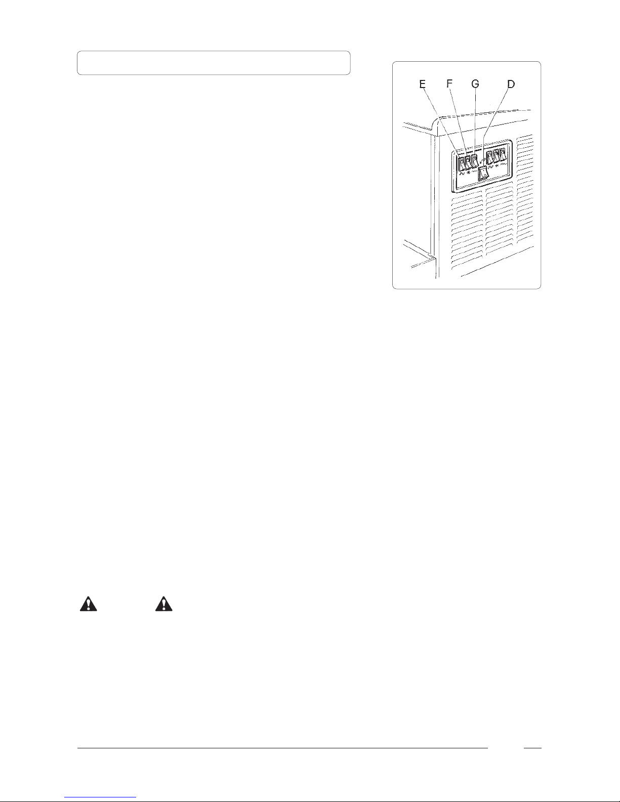
a) Attivare l’interruttore generale (D) (vedi fig. 7);
b) Ogni vasca è comandata da 3 interruttori che
azionerete come segue:
- per ottenere granita o sorbetto: selezionare
l’interruttore (E) per avviare gli organi miscelatori (la
contemporanea accensione del led verde, collocato
sull’interruttore, conferma l’avvenuta selezione),
successivamente selezionare l’interruttore (F) per
azionare l’impianto frigorifero.
Nota: La macchina è dotata di un sistema di ritardo
per l’accensione dei compressori per cui il led verde
relativo all’interruttore (F) si accenderà solamente
dopo 4 minuti dalla sua accensione.
- Per ottenere bibita fredda: selezionare l’interruttore
(E) per avviare gli organi miscelatori (la contem poranea accensione del led verde, collocato
sull’interruttore, conferma l’avvenuta selezione),
successivamente, selezionare l’interruttore (G) per
azionare il sistema di raffreddamento a temperatura
positiva.
Attenzione !!
Nel caso in cui la macchina venga spenta alla sera, con
le vasche piene, anche parzialmente, si può verificare la
formazione di uno strato di ghiaccio solido in superficie,
per effetto della naturale separazione del prodotto non
mescolato. In tal caso, prima di riaccendere la macchina
è bene togliere questo strato di ghiaccio superficiale onde
evitare danni alla coclea miscelatrice.
Fig. 7
Attenzione: Gli interruttori F e G non devono mai essere
accesi contemporaneamente.
6 - SPIEGAZIONE DEGLI INTERRUTTORI E RELATIVO USO

8
Fig. 8
7 - COLLEGAMENTO ALLA RETE ELETTRICA
Prima di inserire la spina nella presa di alimentazione,
come già spiegato nel paragrafo precedente, è
necessario che per la Vs. sicurezza prendiate attenta
visione delle seguenti precauzioni.
- La sicurezza elettrica di questo apparecchio è
raggiunta soltanto quando lo stesso è
correttamente collegato ad un efficace
impianto di messa a terra eseguito
come previsto dalle vigenti normative
nazionali di sicurezza. Il costruttore non
può essere quindi considerato responsabile per
eventuali danni causati dalla mancanza di messa a
terra dell’impianto.
- E’ indispensabile predisporre, per una corretta e
sicura installazione, un’apposita presa comandata
da un interruttore onnipolare con distanza di
apertura dei contatti uguale o superiore a 3 mm,
conforme alle vigenti normative nazionali di
sicurezza (vedi fig. 8).
- Accertarsi che il cavo di alimentazione, per tutta la
sua lunghezza non venga in nessun modo
schiacciato, non usare prolunghe e, per staccare la
spina, afferrare la stessa effettuando trazione
dolce, dopo azionato (staccato) l’interruttore.
- Non ostruire le griglie di ventilazione e di
dissipazione del calore in quanto una cattiva
aerazione, oltre a determinare la diminuzione di
rendimento ed un cattivo funzionamento, può
provocare seri danni all’apparecchio.
IMPORTANTE:
SE IL CAVO D’ALIMENTAZIONE È DANNEGGIATO,
ESSO DEVE ESSERE SOSTITUITO SOLAMENTE DA
PERSONALE QUALIFICATO, IN MODO DA PREVENIRE
OGNI RISCHIO.

9
8 - MODALITA’ D’USO
a) Per erogare il prodotto, posizionare il bicchiere sotto al
rubinetto
(I) ed tirare la leva (L) (vedi fig. 9).
b) Regolazione della consistenza:
per variare la consistenza del prodotto, agire sulla vite
collocata nel retro della macchina (fig. 10); girando in
senso orario, il prodotto diventerà meno denso, girando
in senso antiorario, il prodotto diventerà più denso.
Attenzione !!
Questo dispositivo agisce solo sulla consistenza del
prodotto da erogare (più o meno denso) e non agisce
assolutamente sulla temperatura di raffreddamento
del prodotto.
Attenzione !!
Quando il livello della granita all’interno della vasca è
sotto alla coclea miscelatrice, onde evitare che il prodotto
diventi troppo denso, è necessario spegnere l’impianto
frigorifero mediante l’interruttore
(F) oppure provvedere al rabbocco della vasca.
Fig. 9
Fig. 10

10
9 - OPERAZIONI DI PULIZIA E SANITIZZAZIONE
Fig. 11
Fig. 12
Attenzione !!
Tutte le operazioni devono essere effettuate dopo aver
spento l’interruttore generale della macchina.
Al fine di avere sempre un buon funzionamento
dell’apparecchio, è indispensabile effettuare, tutte le
sere, le operazioni di pulizia attenendosi alle seguenti
istruzioni:
a) Estrarre il dispositivo di miscelazione superiore (O)
spingendolo leggermente all’indietro per poterlo
disincastrare dalla propria sede (vedi fig. 11).
b) Svitare e sfilare i pomelli (P), abbassare la vasca (A)
al fine di eliminare eventuali residui di prodotto
attraverso il rubinetto di uscita (I) (vedi fig. 12).
c) Tirare la vasca verso l’esterno, come raffigurato, per
poterla togliere totalmente dalla propria sede (vedi fig. 13).
Lavare accuratamente la vasca evitando l’uso di
detersivi o polveri abrasive che potrebbero
danneggiarla.
Fig. 13

11
d) Pulizia del rubinetto:
- premere contemporaneamente sulle due alette di
blocco (Q) e sollevare il rubinetto (I) per estrarlo
dalla propria sede (vedi fig. 14).
- Smontare il rubinetto tenendo premuto verso il
basso il corpo (R) sfilando al leva (L) dalla propria
sede (vedi fig. 15).
- Lavare accuratamente ogni singola parte con acqua
calda e detersivo per stoviglie, risciacquare bene e
procedere al rimontaggio.
e) Svitare il pomello di fissaggio (S) nel senso della
freccia (filettatura a sinistra) e procedere
all’estrazione del gruppo di miscelazione (U) e delle
guarnizioni di tenuta (X) e (T) (vedi fig. 16).
f) Lavare accuratamente ogni singola parte, pulire bene
il piano (Y) e l’evaporatore (Z) (vedi fig. 17).
Fig. 14
Fig. 15
Fig. 16
Fig. 17

12
g) Procedere al rimontaggio del gruppo di miscelazione
attenendosi alle seguenti operazioni (vedi fig. 18):
- è indispensabile spalmare la guarnizione (O) con
grasso di vaselina per ridurre l’attrito e limitarne
l’usura.
- rimontare la guarnizione (P) prestando attenzione al
verso (fig. 18 bis);
- rimontare la spirale raschiante (N) avendo cura che
la sua testata si incastri perfettamente con l’albero
di guida.
- fissare tutti i componenti avvitando il pomello (M) in
senso antiorario.
h) Rimontare la vasca (A) collocandola nella propria sede
accertandosi che faccia esattamente tenuta con la
propria guarnizione (vedi fig. 19). Per agevolare il
rimontaggio consigliamo inoltre di inumidire la parte
posteriore della vasca nel punto in cui la stessa
combacia con la sua guarnizione di tenuta.
i) Fissare la vasca (A) tenendola sollevata fino a quando
il pomello (S) è in fase con la sua sede (K); dopodichè
avvitare saldamente, ma senza esercitare forza
eccessiva, onde correre il rischio di incrinare i raccordi
della filettatura, i due pomelli (P) (vedi fig. 20).
l) Rimontare il rubinetto avendo cura di cospargere con
grasso di vaselina le guarnizioni (J) per agevolare lo
scorrimento del rubinetto nella propria sede fino a
completo inserimento (vedi fig. 21).
Attenzione: il non perfetto scorrimento del rubinetto
compromette la tenuta dello stesso.
Fig. 18
Fig. 18 bis
Fig. 19
Fig. 20

13
m) Procedere al rimontaggio del dispositivo di
miscelazione superiore (O) facendo in modo che la
sua corona dentata sia in fase con quella inferiore in
modo da facilitare il perfetto incastro del perno
anteriore nella propria sede collocata sulla vasca (vedi
fig. 22).
n) Smontare la vaschetta raccogligocce (AA) ruotandola
leggermente verso l’alto e tirandola verso l’esterno
(vedi fig. 23).
Lavare accuratamente ogni parte e procedere al
rimontaggio seguendo le operazioni sopracitate al
contrario avendo cura di reinserire il tubo di scarica
condensa (AB) nella propria sede.
Fig. 23
Fig. 22
Fig. 21

14
10 - MANUTENZIONE STRAORDINARIA
11 - ESCLUSIONE DI RESPONSABILITÁ
Attenzione !!
Al fine di garantire un buon rendimento dell’impianto frigo
è indispensabile effettuare periodicamente una buona
pulizia del condensatore, procedendo come segue:
- togliere tensione alla macchina;
- togliere il pannello sinistro FROSTY DREAM 2;
- togliere il pannello sinistro FROSTY DREAM 3;
- con un pennello rimuovere la polvere infiltratasi tra le
lamelle del condensatore (vedi fig. 24).
Per poter accedere alla lampadina del coperchio luminoso
per eventuali sostituzioni, fare leva sul coperchietto (AC)
posizionato sopra al coperchio (vedi fig. 25).
Per accedere alla regolazione dei termostati ed alle sedi
dei fusibili, togliere il fianchetto grigliato del lato destro
(lato comandi).
Per accedere inoltre al vano apparecchiature per
effettuare eventuali operazioni di manutenzione
straordinaria, svitare tutta la carcassa inox.
Fig. 24
Fig. 25
La casa costruttrice declina ogni forma di responsabilità
per eventuali danni che possono direttamente od
indirettamente derivare a persone, cose, animali in
conseguenza della mancata osservanza di tutte le
prescrizioni indicate nel presente manuale e concernenti
specialmente le avvertenze in tema di installazione, uso e
manutenzione dell’apparecchio.
Il produttore non risponde delle eventuali inesattezze
imputabili ad errori di stampa o di trascrizione contenute
nel presente manuale; si riserva di apportare quelle
modifiche che ritenesse necessarie o utili, anche
nell’interesse dell’utilizzatore, senza pregiudicare le
caratteristiche essenziali di funzionalità e sicurezza.

15
INDEX
1 IMPORTANT WARNINGS AND
SUGGESTIONS pg. 16
2 TECHNICAL CHARACTERISTICS pg. 16
3 INSTRUCTIONS FOR MACHINE
TRANSPORT pg. 16
4 INSTALLATION pg. 17
5 START-UP PROCEDURES pg. 18
6 EXPLANATION OF THE SWITCHES
AND THEIR USES pg. 19
7 CONNECTION TO POWER SUPPLY
MAINS pg. 20
8 MACHINE OPERATION pg. 21
9 CLEANING AND SANITISING
PROCEDURES pg. 22
10 SELECT MAINTENANCE pg. 26
11 DISCLAIMER pg. 26
Dear Client,
we would like to congratulate you for having chosen a
high quality product which will surely meet all your expectations. While thanking you for the preference you
have given us, we invite you to carefully read the following
instruction manual before operating your
FROSTY DREAM 2, FROSTY DREAM 3 slush machine.

16
1 - IMPORTANT WARNINGS AND SUGGESTIONS
The present instruction manual is an important part
of the FROSTY DREAM slush machine and must be
kept for any future consultation.
Carefully read the warnings contained in this
instruction manual before installing and operating
the FROSTY DREAM slush machine.
Besides providing information on routine
maintenance of the slush machine and aiding the
technical assistants in the detection and repair of
possible malfunctions, the objective of this manual is
to take advantage of the maximum potentials of the
FROSTY DREAM slush machine in order to adapt
the machine to the specific needs of the various
countries where it will be used.
Modification of, or any attempt to modify this
machine, is extremely dangerous and will cancel any
form of warranty.
All maintenance procedures must be performed by
expertly qualified personnel. The attempt to repair
the machine by unqualified persons is dangerous
and may cause serious damage to the machine.
2 - TECHNICAL CHARACTERISTICS
Specification plate
The voltage and frequency rates are found on the
specification plate.
3 - INSTRUCTIONS FOR MACHINE TRANSPORT
In order to prevent the oil contained in the compressor
from flowing into the cooling circuit, it is necessary to
always carry, store and handle the slush machine in a
vertical position, following the instructions found on the
packaging.
The special wooden pallet, equipped with fork-lift slots,
allow the machine to be moved with common handling
and lifting equipment.

17
Fig. 2
a) Remove the packing material from the machine, then
slide it off from the top (see fig. 1).
b) Identifying the machine
- once the packaging has been removed, check that
the machine which has been delivered is exactly the
machine ordered by verifying that the specifications
indicated on the invoice or on the shipping bill are
the same as those found on the specification plate.
c) Tool kit:
on opening the machine’s packing you will find the
following equipment:
- this instruction manual plus the EU certificate of
conformity;
- 1 tube of Vaseline to be used for the machine’s
maintenance (see paragraph h. page 24) and one
front seals for each bowl;
- 2 bags, each one containing a drip container and an
upper mixing device; proceed with the installation of
these two components for each individual tank
following the figures 22 and 23, found on page 25 of
this manual.
d) Insert the electricity cable for the illuminated cover in
the respective plug located on the cover itself.
e) Positioning the machine
- the main body of the machine must be well
ventilated. Installation of the machine near a heat
source should be avoided. A room temperature
between 15°C and 25°C is suggested (fig. 2).
The luminous covers can be positioned back to front
according to the needs of the operators.
Important
Any packing materials left within the reach of children may
become potential safety hazards.
Fig. 1
4 - INSTALLATION

18
5 - START-UP PROCEDURES
Fig. 6
Fig. 5
Fig. 4
Fig. 3
a) In a separate container, dilute and mix the product with
water, according to the directions given by the
manufacturer (see figure 3).
Warning !!
Make sure that the mixture has a 13% minimum sugar
content; a lower concentration could seriously damage the
mixing parts, as well as the gearmotors.
NEVER USE ONLY WATER.
b) Pour the product obtained into the bowl (A) (see figure
4).
c) Replace the luminous cover (B) (see figure 5).
d) Insert the plug into an electrical outlet (see fig. 6).
e) Turn on the main switch
(D) (see figure 7).
BEFORE STARTING THE MACHINE, CARRY OUT
THE CLEANING AND SANITIZATION OPERATIONS
DESCRIBED IN PARAGRAPH 9

19
a) Activate the general switch (D) (see figure 7):
b) Each tank is controlled by three switches which are
activated as follows:
- to make ice slush or sorbets: first select the switch
(E) to start up the mixer components (the green
LED on the switch will light up to confirm the
selection has been made), then select the switch
(F) to activate the cooling system.
N.B. The machine is equipped with a delay system
for the activation of the compressors, so the green
LED for the switch (F) will not light up until four
minutes after it has been turned on.
- To make cold drinks: first select the switch (E) to
start up the mixer components (the green LED on
the switch will light up to confirm the selection has
been made), then select the switch (G) to activate
the cooling system at a positive temperature.
Warning: Never turn all the switchs F and G on at the
same time.
Warning !!
If the machine is turned off at night, with the bowls filled,
or just partially filled, a layer of solid ice may form on the
surface, due to the natural separation of the unmixed
product. In this case, before turning the machine back
on, remove the layer of superficial ice, so as to prevent
damage to the mixing spiral.
6 - EXPLANATION OF THE SWITCHES AND THEIR USES
Fig. 7

20
Fig. 8
7 - CONNECTION TO POWER SUPPLY MAINS
For your personal safety, before inserting the plug
into the electrical outlet, as previously explained in
paragraph 7, carefully read the following
precautions:
- The electrical safety of the FROSTY DREAM slush
machine can only be achieved if the machine is
properly connected to an efficient grounding
system, in compliance with current national safety
standards. Therefore, the manufacturer cannot be
held responsible for damage and/or injury caused
by failure to properly ground the machine.
- For a safe and correct installation, it is necessary to
provide for a special outlet, with contacts having an
open distance equal to or greater than 3 mm,
controlled by an omnipolar circuit breaker,
conforming to current national security standards
(see fig. 8).
- The power supply cable must not, in any way, for its
entire length, be compressed, extension cords may
not be used, and finally, the plug must be removed
from the outlet with a slight pulling movement, after
having first cut-off the power supply.
- Do not obstruct the ventilating grill and heat
dispersion grill, since an insufficient ventilation
may not only reduce the efficiency of the machine,
causing it to function inadequately, but may also
cause serious damage to the machine.
IMPORTANT:
IF THE POWER SUPPLY CABLE IS DAMAGED,
IT MUST BE REPLACED BY QUALIFIED PERSONNEL
ONLY IN ORDER TO PREVENT ALL POSSIBLE RISKS.

21
8 - MACHINE OPERATION
a) To dispense the product, position the cup under the
tap (I) and pull the dispensing lever (L) (see figure 9).
b) Adjusting the consistency.
To alter the consistency of the product, turn the screws
located on the back of the machine in the following
way: clockwise to make the product less dense,
anticlockwise to make the product denser.
Warning !!
This device only changes the consistency of the
product to be dispensed. It does not effect the cooling
temperature of the product.
Warning !!
When the level of the slush inside the bowl is below the
mixing spiral, to prevent the product from becoming too
thick, it is necessary to turn off the refrigerating system by
using the appropriate switch
(F) or by refilling the bowl.
Fig. 9
Fig. 10

22
Fig. 11
Fig. 12
Warning !!
All cleaning procedures must be carried out only after
having turned the general switch of the machine off.
For the machine to function properly, it is indispensable
that the cleaning procedures be carried out every
evening, according to the following instructions:
a) Pull out the upper mixing device (O) by pushing it
slightly backwards, to remove it from its fixed position
(see figure 11).
b) Unscrew and slip off the knobs (P) then lower the
bowl (A) to eliminate any product residue through the
dispensing tap (I) (see fig. 12).
c) Pull the tank outwards, as shown in the figure, and
remove it fully from its seating (see figure 13). Wash
the tank carefully without using detergents or abrasive
powders which could damage it.
Fig. 13
9 - CLEANING AND SANITISING PROCEDURES

23
d) Cleaning the dispensing tap:
- simultaneously apply pressure to the two securing
tabs (Q), and lift the dispensing tap (I) to pull it out of
its fixed position (see figure 14).
- Remove the dispensing tap by keeping the indicated
part (R) pressed down and slipping off the
dispensing lever (L) (see figure 15).
- Thoroughly wash each single part with hot water
and dish washing detergent, rinse well, and
reassemble the parts.
e) Unscrew the securing bolt (S) in the direction of the
arrow (threading on the left), pull off of the mixing unit
(U), and remove the sealing washers (X) and (T) (see
figure 16).
f) Thoroughly wash each single part, and properly base
(Y), as well as the evaporator (Z) (see figure 17).
Fig. 14
Fig. 15
Fig. 16
Fig. 17

24
g) Mount the mixing unit back together, according to the
following procedures (see figure 18):
- it’s indispensable to spread the gaskets (O) with
vaseline grease to reduce friction and thus limit
wear.
- mount the washer (P) making sure it faces the right
direction (fig.18 bis);
- replace the scraper spiral (N), making sure the head
is perfectly engages with the driving shaft;
- secure all the parts into place by screwing the bolt
(M) in a counterclockwise direction.
h) Mount the bowl (A) back on, positioning it into place,
and making sure that it has a tight hold on its washer
(see figure 19). To facilitate this procedure, we also
suggest that the rear part of the bowl be moistened at
the point in which it fits together with its sealing
washers.
i) Secure the bowl (A) by keeping it lifted until the bolt (S)
is aligned with its hole (K), then tightly screw the two
knobs (P), without exerting excessive pressure, so as
not to risk cracking the threading fillets (see
figure 20).
l) Rassemble the parts of the dispensing tap, making
sure that the gaskets (J) are covered with vaseline
grease so that the tap slides smoothly back into its
fixed position, until it’s completely insered (see figure
21).
Warning: the not perfect sliding of the tap compromises its
own seal.
Fig. 18
Fig. 18 bis
Fig. 19
Fig. 20

25
m) Reassemble the upper mixing unit (O) so that its
toothed crown is aligned with the lower crown. This will
allow the front pin to fit perfectly into its fixed position
on the bowl (see figure 22).
n) Remove the liquid-collector tray (AA) turning it slightly
upwards and pulling it forward (see figure 23). Wash
each part thoroughly, then reassemble the parts by
inversely following the procedures described above.
Make sure that the condensation drainage tube (AB)
is reinserted into its correct fixed position.
Fig. 23
Fig. 22
Fig. 21

26
10 - SELECT MAINTENANCE
11 - DISCLAIMER
Warning !!
In order to guarantee for the efficiency of the refrigerating
system, it is essential that the condenser be properly
cleaned at regular intervals, according to the following
procedures:
- disconnect the machine from its power supply;
- remove the left panel of FROSTY DREAM 2;
- remove the left panel of FROSTY DREAM 3;
- with a brush, remove any dust that has infiltrated
between the blades of the condenser (see figure 24).
In order to access the bulb of the luminous cover for
future replacement, press on the small panel (AC) which
is foud on the cover (see figure 25).
To adjust the thermostats and to access the fuses,
remove the grating panel on the right side (control side).
Furthermore, in order to access the instrument
compartment of the machine, so as to carry out any
further select maintenance operations, unscrew the
entire stainless steel casing.
Fig. 24
Fig. 25
The manufacturer declines all responsibility for any
damage and/or injury that might be brought on, directly or
indirectly, to persons, animals or things as a consequence
of failure to comply with the instructions given in this
manual, and particularly, with the warnings concerning
installation, use and maintenance of the machine.
The manufacturer cannot be held responsible for possible
mistakes due to printing or copying errors contained in this
manual.
In addition, the manufacturer reserves the right to modify
his machines in any way deemed necessary or useful for
the machines, as well as for the benefit of the user, yet at
the same time maintaining the essential operative and safety
characteristics of said machines.

27
SOMMAIRE
1 RECOMMANDATIONS ET
CONSEILS IMPORTANTS page 28
2 DONNEES TECHNIQUES page 28
3 INDICATIONS UTILES POUR LE
TRANSPORT page 28
4 INSTALLATION page 29
5 MISE EN MARCHE page 30
6 EXPLICATIONS SUR LES
INTERRUPTEURS ET LEUR
FONCTIONNEMENT page 31
7 CONNEXION AU RESEAU
ELECTRIQUE page 32
8 MODE D’EMPLOI page 33
9 OPERATIONS RELATIVES A LA
PROPRETE ET A L’HYGIENE page 34
10 TRAVAUX D’ENTRETIEN
EXTRAORDINAIRES page 38
11 EXCLUSION DE RESPONSABILITE page 38
Cher Client,
nous sommes heureux que vous ayez choisi un produit
de qualité qui saura sûrement répondre à vos attentes.
Nous vous remercions de la confiance que vous avez
bien voulu nous accorder et nous vous invitons à consulter attentivement ce manuel d’instructions avant d’utiliser
votre machine à granité FROSTY DREAM 2, FROSTY
DREAM 3.

28
Le présent manuel fait partie intégrante du FROSTY
DREAM et vous devrez le garder soigneusement afin
de pouvoir le consulter à n’importe quel moment.
Lisez attentivement les recommandations qui sont
contenues dans cette notice avant d’installer et
d’employer l’FROSTY DREAM.
Ce manuel donne des informations sur l’entretien
ordinaire de la machine à granité et il aide les
techniciens à rechercher les pannes éventuelles et à
les réparer. En outre, il se propose de stimuler au
maximum l’exploitation des capacités de la machine
afin de pouvoir l’adapter aux exigences propres aux
différents pays dans lesquels elle sera utilisée.
Modifier ou essayer de modifier cet appareil est
extrêmement dangereux et, en plus, cela comporte la
déchéance de toute sorte de garantie.
Il est nécessaire que les travaux d’entretien soient
effectués par un personnel qualifié
professionnellement; n’essayez jamais de le réparer
vous-même car l’intervention de personnes non
compétentes est non seulement dangereuse mais en
plus elle peut provoquer de graves dommages.
2 - DONNEES TECHNIQUES
Données de la plaque d’immatriculation
Les valeurs de la tension de la fréquence sont
indiquées sur la plaque d’immatriculation.
1 - RECOMMANDATIONS ET CONSEILS IMPORTANTS
3 - INDICATIONS UTILES POUR LE TRANSPORT
Afin d’éviter que l’huile qui se trouve dans le
compresseur ne coule dans le circuit réfrigérant, il faut
transporter, emmaganiser et déplacer la machine en
position verticale et en respectant les indications écrites
sur l’emballage.
Sa platte-forme spéciale en bois, munie des
emplacements spéciaux pour enfiler les fourches, permet
de la déplacer en employant les moyens habituels de
déplacement et de levage.

29
Fig. 2
4 - INSTALLATION
Fig. 1
a) Libérez l’appareil de son emballage et ensuite
retirez-le par le haut (voir fig. 1).
b) Reconnaissance de la machine
- après avoir enlevé l’emballage vous devez vérifier
que l’appareil qui vous a été livré soit exactement
celui que vous avez commandé en contrôlant que
les données indiquées en détail sur la facture ou
sur le bulletin de livraison correspondent bien à
celles qui se trouvent sur la plaque
d’immatriculation.
c) Equipement de la machine:
quand vous ouvrirez l’emballage, vous trouverez, à
l’intérieur des bacs, l’équipement suivant:
- la présente notice d’instructions accompagnée de la
déclaration de conformité CE relative;
- 1 tube de vaseline à utiliser pour les différents
travaux d’entretien sur la machine (voir paragraphe
n° h, page 36) et une joint d’étanchéité frontaux pour
chaque bac;
- 2 sacs contenant chacun un petit bac pour recueillir
les gouttes et 1 dispositif supérieur pour mélanger;
procédez à l’installation de ces éléments pour
chacun des bacs en suivant les figures n° 22, page
37 et n° 23, page 37 de la présente notice;
d) Branchez le câble pour la lumière du couvercle
lumineux sur la prise correspondante qui se trouve sur
ce couvercle.
e) Mise en place
- faites en sorte que le revêtement métallique de la
machine soit bien aéré et ne l’installez pas, si
possible, à proximité de sources de chaleur; nous
conseillons une température ambiante allant de 15
à 25 degrés C (fig. 2).
Selon les exigences de l’opérateur, les couvercles
lumineux peuvent être positionnés avec le devant
derrière.
Important
Ne laissez à la portée des enfants aucun des éléments
de l’emballage car ils pourraient représenter une source
de danger.

30
a) Délayez et mélangez, dans un récipient à part, le
produit avec de l’eau en suivant les indications du
producteur (voir fig. 3).
Fig. 6
Attention !!
Vérifiez que le mélange contienne un minimum de 13%
de sucre; une concentration plus faible pourrait
endommager gravement les organes mélangeurs et les
motoréducteurs. N’EMPLOYEZ JAMAIS DE L’EAU
TOUTE SEULE.
b) Versez le produit que vous avez obtenu dans le bac
(A) (voir fig. 4).
c) Repositionnez le couvercle lumineux (B) (voir fig. 5).
d) Introduisez la fiche dans la prise d’alimentation
électrique (voir fig. 6).
e) Actionnez l’interrupteur général
(D) (voir fig. 7).
Fig. 5
Fig. 4
Fig. 3
5 - MISE EN MARCHE
AVANT D’EFFECTUER LA MISE EN MARCHE DE
LA MACHINE, PROCÉDER AUX OPÉRATIONS DE
NETTOYAGE ET D’ASSAINISSEMENT DÉCRITES
DANS LE PARAGRAPHE 9.

31
a) Actionnez l’interrupteur général (D) (voir fig. 7):
b) Chaque bac est commandé par 3 interrupteurs que
vous devez actionner comme il suit:
- pour obtenir un granité ou un sorbet: sélectionnez
l’interrupteur (E) afin de mettre en marche les
organes qui servent à mélanger (le voyant lumineux
vert s’allume, confirmant que la sélection s’est
effectuée), ensuite, sélectionnez l’interrupteur (F)
pour mettre en marche l’installation frigorifique.
Nota: la machine est équipée d’un système de
retardement pour l’allumage des compresseurs et,
par conséquent, le voyant lumineux vert qui
correspond à l’interrupteur (F) ne s’allume que 4
minutes après son allumage.
- pour obtenir une boisson froide: sélectionnez
l’interrupteur (E) afin de mettre en marche les
organes qui servent à mélanger (le voyant lumineux
vert s’allume, confirmant que la sélection s’est
effectuée), ensuite, sélectionnez l’interrupteur (G)
pour mettre en marche le système de
refroidissement à température positive.
Attention: Les interrupteurs F et G ne doivent pas être
allumés simultanément.
Attention !!
Au cas où vous éteindriez la machine, le soir, avec les
bacs pleins, même partiellement, il peut arriver qu’il se
forme une couche de glace solide sur le dessus, à cause
de la séparation naturelle du produit quand il n’est pas
mélangé. Dans ce cas-ci, avant de réallumer la machine,
il vaut mieux enlever cette couche de glace superficielle
afin d’éviter qu’elle n’endommage le groupe mélangeur.
6 - EXPLICATIONS SUR LES INTERRUPTEURS ET LEUR
FONCTIONNEMENT
Fig. 7

32
Fig. 8
7 - CONNEXION AU RESEAU ELECTRIQUE
Avant d’introduire la fiche dans la prise
d’alimentation, comme il a déjà été expliqué au
paragraphe précédent, il faut, pour votre propre
sécurité, que vous preniez attentivement
connaissance des précautions suivantes.
- La sécurité électrique de cet appareil n’est assurée
que s’il est correctement connecté à une installation
de mise à terre efficace et exécutée comme il est
prévu par les règlementations nationales sur la
sécurité en vigueur. Le constructeur ne peut par
conséquent être tenu pour responsable des
dommages éventuels qui seraient causés par
l’absence de mise à terre de l’installation.
- Il faut absolument prévoir, pour avoir une
installation correcte et sûre, une prise spéciale
commandée par un interrupteur omnipolaire dont la
distance d’ouverture des contacts soit de 3 mm ou
plus, conformément aux règlementations nationales
sur la sécurité en vigueur (voir fig. 8).
- Vérifiez que le câble d’alimentation ne soit écrasé
en aucune façon et en aucune partie, n’employez
pas de rallonges et, pour détacher la fiche, prenez
celle-ci en tirant doucement après avoir actionné
(détaché) l’interrupteur.
- N’obstruez pas les grilles de ventilation et de
dispersion de la chaleur car une mauvaise aération,
non seulement entraîne une diminution du
rendement et un mauvais fonctionnement, mais en
plus, peut provoquer de graves dommages à
l’appareil.
IMPORTANT:
SI LE CABLE D’ALIMENTATION EST ENDOMMAGÉ, IL
NE DOIT ETRE REMPLACÉ QUE PAR UN PERSONNEL
QUALIFIÉ POUR NE PAS COURIR DE RISQUES.

33
a) Pour distribuer le produit, placez le verre sous le
robinet (I) tirez sur (L) (voir fig. 9).
b) Réglage de la consistance:
pour changer la consistance du produit, agissez sur la
vis qui se trouve sur le derrière de la machine (fig. 10);
quand vous la tournez dans le sens des aiguilles d’une
montre, le produit deviendra moins dense; quand vous
la tournez dans le sens inverse des aiguilles d’une
montre, le produit deviendra plus dense.
Attention !!
Ce dispositif n’agit que sur la densité du produit à
distribuer (plus ou moins dense) et n’agit absolument
pas sur la température de refroidissement du produit.
Attention !!
Quand le niveau du granité qui est à l’intérieur du bac est
au-dessous du groupe mélangeur, pour éviter que le
produit ne devienne trop dense, vous devez éteindre
l’installation frigorifique au moyen de l’interrupteur
(F) ou vous devez remplir le bac.
Fig. 9
Fig. 10
8 - MODE D’EMPLOI

34
Fig. 11
Fig. 12
Fig. 13
9 - OPERATIONS RELATIVES A LA PROPRETE
ET A L’HYGIENE
Attention !!
On ne doit effectuer aucune opération de nettoyage
avant d’avoir étendu l’interrupteur général de la
machine.
Pour que votre appareil fonctionne toujours bien, il est
indispensable que vous le nettoyiez tous les soirs en
vous conformant aux instructions suivantes:
a) Retirez le dispositif supérieur (O) qui sert à mélanger,
en le poussant légèrement en arrière pour pouvoir le
dégager de son propre logement (voir fig. 11).
b) Dévissez et retirez le pommeaux (P), baissez le bac
(A) afin d’éliminer les résidus de produit éventuel à
travers le robinet de sortie (I) (voir fig. 12).
c) Tirez le bac vers l’extérieur, comme sur la figure, pour
pouvoir le retirer entièrement de son logement (voir
fig. 13). Lavez soigneusement le bac mais
n’employez pas de détergents ou de poudres
abrasives l’endommager.

35
d) Nettoyage du robinet:
- appuyez en même temps sur les deux ailettes de
blocage (Q) et soulevez le robinet (I) pour le faire
sortir de son propre logement (voir fig. 14).
- Démontez le robinet en tenant son corps (R) pressé
vers le bas et en retirant le levier (L) de son propre
logement (voir fig. 15).
- Lavez soigneusement chaque partie avec de l’eau
chaude et du détersif pour la vaisselle. Rincez
soigneusement et procédez au remontage.
e) Dévissez le pommeau de fixation (S) dans le sens de
la flèche (filetage à gauche) et retirez le groupe
mélangeur (U) ainsi que les joints d’étanchéité (X) et
(T) (voir fig. 16).
f) Lavez soigneusement chacune de ces parties,
nettoyez bien le plan (Y) et l’évaporateur (Z) (voir fig.
17).
Fig. 14
Fig. 15
Fig. 16
Fig. 17

36
g) Procédez au remontage du groupe mélangeur en vous
conformant aux instructions suivantes (voir fig. 18):
- c’est indispensable de étaler le joint (O) avec du
gras de vaseline réduire le frottement et limiter ainsi
l’usure.
- remontez le joint (P) en faisant attention à son sens
(voir fig. 18 bis).;
- remontez la spirale qui sert à racler (N) en faisant
attention à ce que sa tête s’encastre parfaitement
avec l’arbre de direction.
- fixez tous les éléments en vissant le pommeau (M)
dans le sens contraire à celui des aiguilles d’une
montre.
h) Remontez le bac (A) en le plaçant dans son propre
logement et en contrôlant qu’il adhère parfaitement
avec sa propre jointe pour que l’étanchéité soit
garantie (voir fig. 19). Pour que le remontage soit plus
facile, nous vous conseillons, en outre, d’humidifier la
partie postérieure du bac à l’endroit où il se joint à la
jointe d’étanchéité.
i) Fixez le bac (A) en le tenant soulevé jusqu’à ce que le
pommeau (S) soit en correspondance de son
logement (K); après quoi, vissez solidement les deux
pommeaux (P), mais sans exercer une force excessive
pour ne pas courir le risque de fendiller les raccords
du filetage (voir fig. 20).
l) Remontez le robinet en ayant soin de graisser les
joints (J) avec de la vaseline pour faciliter l’introduction
du robinet dans son propre logement jusqu’à ce qu’il y
entre complètement (voir fig. 21).
Attention: un pas perfect fluage du robinet compromet sa
propre étanche.
Fig. 18
Fig. 18 bis
Fig. 19
Fig. 20

37
m) Procédez au remontage du dispositif supérieur (O) qui
sert à mélanger, en veillant à ce que sa couronne
dentée soit en correspondance avec celle qui se
trouve au-dessous, de façon à faciliter l’encastrement
parfait du pivot antérieur dans son propre logement
qui est situé sur le bac (voir fig. 22).
n) Démontez la cuve qui sert à recueillir les gouttes (AA)
faisant tourner légèrement vers le haut et en la tirant
vers l’extérieur (voir fig. 23).
Lavez soigneusement chaque partie et procédez au
remontage en suivant les opération décrites ci-dessus
mais dans le sens contraire et en ayant soin de
réintroduire le tube de décharge de l’eau de
condensation (AB) dans son propre logement.
Fig. 23
Fig. 22
Fig. 21

38
10 - TRAVAUX D’ENTRETIEN EXTRAORDINAIRES
11 - EXCLUSION DE RESPONSABILITE
Attention !!
Afin de garantir un bon rendement de l’installation
frigorifique, il est indispensable d’effectuer périodiquement
un nettoyage à fond du condensateur, en procédant
comme il suit:
- débranchez la machine;
- retirez le panneau gauche FROSTY DREAM 2;
- retirez le panneau gauche FROSTY DREAM 3;
- a l’aide d’un pinceau, enlevez la poussière qui s’est
infiltrée entre les lamelles du condensateur (voir fig. 24).
Pour pouvoir accéder à l’ampoule du couvercle
lumineux, éventuellement pour la remplacer, faites levier
sur le petit couvercle (AC) qui se trouve au-dessus du
couvercle (voir fig. 25).
Pour accéder au dispositif de réglage des thermostats
et aux logements des fusibles, enlevez la petite grille du
côté droit (côté des commandes).
Pour accéder en outre à l’emplacement des
appareillages pour effectuer d’éventuelles opérations
d’entretien extraordinaire, dévissez tout le revêtement
en inox.
Fig. 24
Fig. 25
La Maison constructrice décline toute forme de
responsabilité pour d’éventuels dommages aux
personnes, aux animaux ou aux choses qui peuvent
dériver directement ou indirectement du non-respect de
toutes les prescriptions indiquées dans le présent manuel
d’instructions et concernant spécialement les
recommandations au sujet de l’installation, de l’emploi et
de l’entretien de l’appareil.
Le producteur ne répond pas des éventuelles
inexactitudes imputables à des fautes d’impression ou de
transcription contenues dans ce manuel; il se réserve le
droit d’apporter les modifications qu’il jugerait nécessaires
ou utiles, ne serait-ce que dans l’intérêt de l’utilisateur,
sans compromettre les caractéristiques essentielles de
fonctionnement et de sécurité.

39
INHALT
1 WICHTIGE HINWEISE UND
RATSCHLÄGE Seite 40
2 TECHNISCHE DATEN Seite 40
3 NÜTZLICHE ANGABEN FÜR DEN
TRANSPORT Seite 40
4 INSTALLATION Seite 41
5 INBETRIEBNAHME Seite 42
6 ERKLÄRUNG DER SCHALTER UND
IHRER BENUTZUNG Seite 43
7 ELEKTRISCHER ANSCHLUSS Seite 44
8 EINSATZ Seite 45
9 REINIGUNG UND STERILISIERUNG Seite 46
10 AUSSERORDENTLICHE
WARTUNGSARBEITEN Seite 50
11 HAFTUNGSAUSSCHLIESSUNGEN Seite 50
Sehr geehrter Kunde,
Sie haben sich für ein Qualitätsprodukt entschieden, das
mit Sicherheit Ihre Erwartungen erfüllen wird.
Wir danken Ihnen für diese Wahl und möchten Sie bitten,
diese Bedienungsanleitung sorgfältig zu lesen, bevor
Sie Ihre Granita-Maschine FROSTY DREAM 2, FROSTY
DREAM 3 in Betrieb nehmen.

40
1 - WICHTIGE HINWEISE UND RATSCHLÄGE
Die vorliegende Anleitung stellt einen integralen
Bestandteil von FROSTY DREAM dar und muß zur
Konsultation aufbewahrt werden.
Lesen Sie die in diesem Handbuch enthaltenen
Hinweise aufmerksam durch, bevor Sie FROSTY
DREAM installieren und benutzen.
Dieses Handbuch informiert über die
ordnungsgemäße Wartung der Granita-Maschine,
dient den Technikern bei der Suche und der
Reparatur eventueller Störungen und setzt sich das
Ziel, eine optimale Nutzung der Maschine zu
ermöglichen, um sie an die spezifischen
Anforderungen der verschiedenen Länder
anzupassen, in denen sie eingesetzt wird.
Abänderungen und versuchte Abänderungen des
Gerätes führen zum sofortigen Verfall jeder Art von
Garantie und sind ausgesprochen gefährlich.
Die erforderlichen Wartungsarbeiten müssen von
qualifiziertem Fachpersonal ausgeführt werden;
versuchen Sie nie, selbst Eingriffe durchzuführen,
denn dies ist gefährlich und kann schwere
Beschädigungen hervorrufen.
2 - TECHNISCHE DATEN
Daten auf dem Typenschild
Die Werte für die Spannung und die Frequenz
werden auf dem Typenschild angegeben.
3 - NÜTZLICHE ANGABEN FÜR DEN TRANSPORT
Der Getränkeautomat muß unter Beachtung der
Angaben auf der Verpackung aufrecht transportiert,
gelagert und bewegt werden, um zu verhindern, daß das
im Kompressor enthaltene Öl ausläuft.
Das eigene Holzverpackung ist mit Schlitzen versehen,
vorgesehen und ermöglicht eine Aufstellung mit
herkömmlichen Stapel- und Hebegeräten.

41
4 - INSTALLATION
Abb. 1
a) Entfernen Sie die Verpackung, indem Sie den Karton
nach oben abziehen (siehe Abb. 1).
b) Identifizierung der Maschine
- Nach der Entfernung der Verpackung muß überprüft
werden, ob das gelieferte Gerät mit dem von Ihnen
bestellten genau übereinstimmt, indem kontrolliert
wird, ob die Angaben auf der Rechnung oder dem
Lieferschein mit den Angaben auf dem Typenschild
übereinstimmen.
c) Ausstattung der Maschine
beim Öffnen der Verpackung befindet sich die folgende
Ausstattung in der Wanne:
- das vorliegende Anweisungshandbuch und die
entsprechende CE-Konformitätserklärung;
- 1 Tube Vaseline für die Wartungsarbeiten an der
Maschine (siehe Abschnitt Nr. h, Seite 48) und eine
Dichtungen für jede Wanne;
- 2 Beutel, die jeweils Schale zum Auffangen der
Tropfen und 1 obere Mischvorrichtung; bei der
Installation dieser beiden Komponenten für jede
einzelne Wanne die Abbildungen Nr. 22 und Nr. 23
auf Seite 49 des vorliegenden Handbuches
beachten;
d) Das Kabel für den Leuchtdeckel in den
entsprechenden Anschluss auf dem Deckel selbst
einstecken.
e) Aufstellung
- stellen Sie die Granita-Maschine so auf, daß das
Gehäuse gut gelüftet wird und vermeiden Sie
Installationen in der Nähe von Wärmequellen; es
wird eine Umgebungstemperatur von 15°C - 25°C
empfohlen (siehe Abb. 2).
Je nach Bedarf können die beleuchteten Deckel in
Richtung Vorder- bzw. Rückseite angebracht werden.
Wichtig
Sämtliche Teile der Verpackung müssen von Kindern
ferngehalten werden, denn sie stellen eine mögliche
Gefahrenquelle dar.
Abb. 2

42
Abb. 6
Abb. 5
Abb. 4
Abb. 3
a) Das Ausgangsprodukt in einem Behälter in Wasser
lösen und vermischen, berücksichtigen Sie dabei die
entsprechende Gebrauchsanweisung (siehe Abb. 3).
Achtung !!
Der Mindestgehalt an Zucker muß bei 13% liegen, da
eine niedrigere Konzentration die Mischteile sowie den
Motor selbst ernsthaft schädigen kann.
NIEMALS NUR WASSER VERWENDEN.
b) Das vorbereitete Gemisch in die Wanne (A) leeren
(siehe Abb. 4).
c) Den beleuchteten Deckel aufsetzen und darauf
achten.
d) Den Netzstecker einstecken (siehe Abbildung 6).
e) Den Hauptschalter betätigen
(D) (siehe Abb. 7).
5 - INBETRIEBNAHME
VOR ANSCHALTEN DER MASCHINE DIE IN
ABSCHNITT 9 BESCHRIEBENEN REINIGUNGS- UND
DESINFIZIERUNGSARBEITEN DURCHFÜHREN.
43
a) Den Hauptschalter (D) betätigen (siehe Abb. 7);
b) Jede Wanne wird von 3 Schaltern guesteuert, die wie
folgt betätigt werden:
- Für Granita oder Sorbett: Den Schalter (E) wählen,
um die Mischvorrichtung zu starten (das
gleichzeitige Aufleuchten der grünen Led auf dem
Schalter bestätigt die Wahl); anschlieβend den
Schalter (F) wählen, um die Kühlanlage zu
aktivieren.
Anmerkung: Die Maschine ist mit einem
System für die Verzögerung der Einschaltung der
Kompressoren ausgestattet und deshalb leuchtet
die Led des Schalters (F) erst 4 Minuten nach
seiner Betätigung auf.
- Für kalte Getränke: Den Schalter (E) wählen, um
die Mischvorrichtung zu starten (das gleichzeitige
Aufleuchten der grünen Led auf dem Schalter
bestätigt die Wahl); anschlieβend den Schalter (G)
wählen, um das Kühlsystem mit positiver
Temperatur zu aktivieren.
Achtung: Die Shalter F und G dürfen nie gleichzeitig
Geschlossen sein.
Achtung !!
Falls das Gerät nach Betriebsschluß mit, auch nur
teilweise, gefüllten Wannen ausgeschaltet wird, bildet
sich eine Eisschicht an der Oberfläche in Folge der
natürlichen Trennung des unvermischten Produktes. In
diesem Falle muß die Eisschicht vor dem Einschalten des
Gerätes entfernt werden, um Schäden an den Mischteilen
zu vermeiden.
Abb. 7
6 - ERKLÄRUNG DER SCHALTER UND IHRER BENUTZUNG

44
Abb. 8
7 - ELEKTRISCHER ANSCHLUSS
Vor dem Einstecken des Netzsteckers, das im
vorausgehenden Abschnitt bereits beschrieben
wurde, müssen die folgenden Sicherheitsmaßnahmen
beachtet werden:
- Die elektrische Sicherheit dieses Geräts wird nur
erreicht, wenn es wie von den geltenden nationalen
Sicherheitsbestimmungen vorgeschrieben
ausreichend geerdet wird. Der Hersteller kann daher
nicht haftbar gemacht werden für Schäden, die auf
einer unzureichenden Erdung der Anlage
zurückzuführen sind.
- Für eine sichere und korrekte Installation muß dem
elektrischen Anschluß ein den geltenden nationalen
Sicherheitsbestimmungen entsprechender
Trennschalter mit einer Kontaktöffnungsweite von
zumindest 3 mm vorgeschaltet werden (siehe
Abbildung 8).
- Stellen Sie sicher, daß das Netzkabel auf seiner
gesamten Länge nicht gequetscht wird, verwenden
Sie keine Verlängerung und ziehen Sie nie am
Netzkabel, sondern immer am Netzstecker selbst,
nachdem Sie den Trennschalter geöffnet haben.
- Achten Sie darauf, daß die Lüftungsschlitze stets
frei sind, da eine schlechte Lüftung die Leistung des
Geräts verringert, zu einem schlechten
Funktionieren führt und außerdem schwere
Beschädigungen des Geräts verursachen kann.
WICHTIG:
WENN DER STROMVERSORGUNGSKABEL
BESCHADIGT IST, MUSS ER NUR DURCH
QUALIFIZIERTES PERSONAL ERSETZT WERDEN, UM
JEGLICHEN RISIKEN ZU VERMEIDEN.

45
Abb. 9
Abb. 10
8 - EINSATZ
a) Zur Produktausgabe das Glas unter den
Ausgabehahn (I) positionieren und den Hebel (L)
ziehen (siehe Abb. 9).
b) Einstellung der Konsistenz:
Zur Änderung der Konsistenz des Produkts die
Schraube auf der Rückseite der Maschine (Abb. 10)
drehen; beim Drehen in Uhrzeigerrichtung wird das
Produkt weniger dicht, beim Drehen in
Uhrzeigerrichtung wird das Produkt dichter.
Achtung !!
Diese Vorrichtung dient lediglich zur Regelung der
Konsistenz des auszugebenden Produkts (mehr
oder weniger zäh) und hat keinen Einfluss auf die
Kühltemperatur.
Achtung !!
Wenn der Mengeninhalt der Granita unter die Mischteile
sinkt, ist es notwendig, das Kühlsystem mittels Schalter
(F) außer Betrieb zu setzen oder die Wanne
wieder aufzufüllen, um eine Eindickung des
Produktes zu vermeiden.

46
Abb. 11
Abb. 12
Achtung !!
Alle Eingriffe mussen vorgenommen werden Nach
dem Öffnen des Hauptschalters der Maschine.
Um stets ein korrektes Funktionieren des Gerätes zu
erlangen, ist es unbedingt notwendig, nach Betriebsende
sämtliche Reinigungsarbeiten wie folgt durchzuführen:
a) Die obere Vorrichtung für das Mischverfahren (O)
herausnehmen, indem man sie leicht nach rückwärts
drückt, um sie aus der Halterung zu heben.
b) Die Knäufe abschrauben und lösen (P), dann die
Wanne (A) senken um samtlichen Restinhalt durch
den Ausgabehann (I) zu leeren (Abb. 12).
c) Die Wanne wie abgebildet nach auβen ziehen, um sie
aus ihrem Sitz zu entfernen (siehe Abb. 13). Die
Wanne sorgfältig reinigen und dabei keine Reiniger
oder Scheuerpulver verwenden, durch die sie
beschädigt werden könnte.
Abb. 13
9 - REINIGUNG UND STERILISIERUNG

47
d) Reinigung des Ausgabehahns:
- gleichzeitig auf die Halterungsrippen (Q) drücken
und den Hahn (I) heben, um ihn aus der
Haltevorrichtung zu lösen (siehe Abb. 14).
- Den Ausgabehahn zerlegen, indem man den
Hauptkörper (R) nach unten drückt und den Hebel
(L) aus der Halterung abzieht (siehe Abb. 15).
- Sämtliche Einzelteile mit warmem Wasser und
Geschirrspülmittel gründlich reinigen und sorgfältig
nachspülen. Alle Teile wieder zusammensetzen.
e) Den fixierknopf (S) in Pfeilrichtung herausdrehen
(Drehrichtung nach links) und sämtliche Mischteile (U),
sowie die Schutzdichtung (X) und (T) entfernen (siehe
Abb. 16).
f) Sämtliche Einzelteile, sowie die Unterlage (Y) und den
Verdampfer (Z) gründlich reinigen (siehe Abb. 17).
Abb. 14
Abb. 15
Abb. 16
Abb. 17

48
g) Den Bauteilsatz des Mischers wie folgt
zusammensetzen (siehe Abb. 18):
- Die Dichtung (O) muss mit Vaselinefett geschmiert
werden, um die Reibung und somit den Verschleiß
zu reduzieren.
- Beim Einsetzen der Dichtung auf die richtige Lage
achten (Abb. 18 bis).;
- Die Schaberspirale (N) wieder einbauen und
dabei darauf achten, dass das Kopfteil perfekt in die
Führungswelle einrastet.
- Sämtliche Einzelteile durch Drehen des
Drehknopfes (M) gegen den Uhrzeigersinn
befestigen.
h) Die Wanne (A) in ihre Halterung einrasten, dabei
auf ein genaues Abschließen mit der Dichtung
achten (siehe Abb. 19). Um das Zusammensetzen
zu erleichtern, empfehlen wir die Wannenrückseite in
Dichtungshöhe zu befeuchten.
i) Die Wanne (A) befestigen, indem man sie bis zum
Einrasten des Drehknopfes (S) in der Halterung (K)
hochhebt; danach schließend, jedoch ohne
Kraftanwendung, anschrauben, um das
Schraubengewinde der beiden Drehknöpfe (P) nicht zu
beschädigen (siehe Abb. 20).
l) Den Ausgabehahn aufsetzen, dabei die Dichtungen (J)
gründlich mit Vaseline einfetten, um das Einfügen und
schließlich das Einrasten des Hahns in der
Halterungsvorrichtung zu erleichtern (siehe Abb. 21).
Achtung: Ein unperfektes Gleiten des Hahns
Beeinträchtigt die Dichtigkeit desselben.
Abb. 18
Abb. 18 bis
Abb. 19
Abb. 20

49
m) Die obere Vorrichtung des Mischsatzes (O) einsetzen,
dabei die beiden Zahnkränze aufeinander einrichten,
um das genaue Einrasten des vorderen Zapfens in die
Halterungsvorrichtung an der Wanne zu erleichtern
(siehe Abb. 22).
n) Die Auffangtasse (AA) abnehmen, indem man sie
leicht nach oben dreht und abzieht (siehe Abb. 23),
danach gründlich reinigen. Das Zusammensetzen der
Einzelteile erfolgt wie oben beschrieben in
umgekehrter Richtung, dabei darauf achten, daß das
Abflußrohr (AB) in seine Halterungsvorrichtung genau
eingepaßt wird.
Abb. 23
Abb. 22
Abb. 21

50
Achtung !!
Um eine gute Leistungsfähigkeit des Kühlsystems zu
garantieren, ist es unbedingt notwendig, den Kondensator
folgendermaßen regelmäßig und sorgfältig zu reinigen:
- die Speisung der Maschine abschalten;
- das linke Paneel der FROSTY DREAM 2 abnehmen;
- das linke Paneel der FROSTY DREAM 3 abnehmen;
- den Staub, der sich zwischen den Lamellen des
Kondensators abgesetzt hat, mit einem Pinsel entfernen
(siehe Abb. 24).
Für ein eventuelles Austauschen der Glühlampe den
kleinen Deckel (AC) an der Oberseite hochheben (siehe
Abb. 25).
Zur Einstellung und Regulierung des Thermostates bzw.
der Sicherungen die rechte Seitenwand
(Kommandoseite) abnehmen.
Für eventuelle außerordentliche Wartungsarbeiten am
Gerät die Edelstahlverkleidung abschrauben.
Abb. 24
Abb. 25
10 - AUSSERORDENTLICHE WARTUNGSARBEITEN
11 - HAFTUNGSAUSSCHLIESSUNGEN
Der Hersteller lehnt jede Art von Haftung für Schäden ab,
die bei Nichtbeachtung der in dem vorliegenden
Handbuch enthaltenen Hinweise und Vorschriften zur
Installation, Benutzung und Wartung des Geräts direkt
oder indirekt an Personen, Gegenständen oder Tieren
verursacht werden.
Der Hersteller haftet nicht für eventuell in dem
vorliegenden Handbuch vorhandene Ungenauigkeiten,
Druckfehler oder Übersetzungsfehler; er behält sich das
Recht vor, auch im Sinne des Benutzers jederzeit und
ohne Vorankündigung ihm notwendig oder nützlich
erscheinende Änderungen an der Maschine
vorzunehmen, ohne daß dadurch die wesentlichen
Eigenschaften der Maschine hinsichtlich Funktionalität
und Betriebssicherheit beeinträchtigt werden.

51
INDICE
1 ADVERTENCIAS Y CONSEJOS
IMPORTANTES pág. 52
2 DATOS TECNICOS pág. 52
3 INDICACIONES ÚTILES PARA
EL TRANSPORTE pág. 52
4 INSTALACIÓN pág. 53
5 OPERACIONES DE PUESTA EN
MARCHA pág. 54
6 FUNCIONALIDAD DE LOS
INTERRUPTORES Y USO
CORRESPONDIENTE pág. 55
7 CONEXIÓN A LA RED
ELÉCTRICA pág. 56
8 MODALIDADES DE USO pág. 57
9 OPERACIONES DE LIMPIEZA Y
SANEAMIENTO pág. 58
10 OPERACIONES DE MANTENIMIENTO
EXTRAORDINARIAS pág. 62
11 EXCLUSION DE
RESPONSABILIDAD pág. 62
Estimado Cliente,
Nos alegramos por Usted que ha elegido un producto de
calidad que seguramente responderá a sus expectativas.
Agradeciendo su preferencia, le invitamos amablemente
a leer atentamente este manual de instrucciones, antes
de utilizar su nueva granizadora FROSTY DREAM 2,
FROSTY DREAM 3.

52
1 - ADVERTENCIAS Y CONSEJOS IMPORTANTES
2 - DATOS TÉCNICOS
Datos de la placa
Los valores de tensión y de la frecuencia aparecen
en la placa de la matrícula.
El presente manual de instrucciones forma parte
de su Granizadora FROSTY DREAM y, por lo tanto,
deberá conservarse para efectuar cualquier tipo de
consulta.
Lean atentamente las advertencias que aparecen en
el presente manual de instrucciones antes de instalar
o utilizar su Granizadora FROSTY DREAM.
Este manual, además de informar sobre el
mantenimiento diario del expendedor y de servir de
ayuda a los técnicos que deban encontrar o reparar
posibles averías, tiene como finalidad que Uds.
aprovechen al máximo las capacidades productivas
de la máquina, para que puedan adaptarla a las
exigencias específicas de los países donde será
utilizada.
Modificar o intentar modificar este aparto no sólo
acarrea la pérdida de cualquier forma de garantía,
sino que puede resultar peligroso.
Es necesario que las operaciones de mantenimiento
sean realizadas por personal especializado; les
aconsejamos vivamente que se abstengan de
intentar reparar la máquina por sí mismos, ya que
además de ser peligroso puede causar daños graves
al sistema.
3 - INDICACIONES ÚTILES PARA EL TRANSPORTE
Para evitar que el aceite que contiene el compresor se
derrame en el circuito refrigerador, es necesario
transportar, almacenar y desplazar el aparato en
posición vertical respetando las indicaciones que
aparecen en el embalaje.
Los modelos están dotados de una base de madera que
presenta unos alojamientos por los que se pueden
introducir las horquillas de las carretillas elevadoras o
cualquier otro medio de desplazamiento o elevación.

53
Fig. 2
a) Liberen el aparato de su embalaje, extrayéndolo
cuidadosamente por la parte superior (véase fig. 1).
b) Inspección de la máquina
- después de haber quitado el embalaje, asegúrense
de que el aparato que han recibido corresponda con
el que Uds. han solicitado y controlen que los
detalles que aparecen en la factura o en el albarán
sean iguales a los mencionados en la placa.
c) Equipo de la máquina
Curando abran el embalaje, dentro de los depósitos
encontrarán el siguiente equipo:
- el presente manual de instrucciones más la
declaración CE de conformidad correspondiente;
- 1 tubo de vaselina para las operaciones de
mantenimiento en la máquina (véase apartado n° h,
página 60) y una junta de estanqueidad frontales por
cada placa;
- 2 bolsas que contienen cada una un recipiente
recoge-gotas y 1 dispositivo de mezcla superior;
instalen estos dos componentes en cada depósito
ateniéndose a las figuras n° 22 de la página 61 y
n° 23 de la página 61 del presente manual;
d) Coloquen el cable de la luz de la tapadera
luminosas en la toma correspondiente que se
encuentra en la misma tapadera.
e) Colocación
- asegúrense de que la carrocería de la máquina esté
bien aireada y procuren no instalarla cerca de
fuentes de calor; se aconseja una temperatura
ambiente entre los 15º y 25º C (véase fig. 2).
Según las exigencias del usuario las tapas luminosas
pueden colocarse en una u otra dirección.
Importante
Todos los elementos del embalaje deben estar fuera del
alcance de los niños ya que pueden ser posibles fuentes
de peligro.
Fig. 1
4 - INSTALACIÓN

54
Fig. 6
Fig. 5
Fig. 4
Fig. 3
a) Diluyan y mezclen, en un recipiente a parte, el
producto con agua respetando las indicaciones del
productor (véase fig. 3).
¡¡ Atención !!
Asegúrense de que la mezcla contenga un mínimo de un
13% de azúcar; una concentración menor podría
provocar serios daños en los órganos mezcladores así
como en los motorreductores. NUNCA USEN SÓLO
AGUA.
b) Viertan el producto así obtenido en el depósito (A)
(véase fig. 4).
c) Vuelvan a colocar la tapa luminosa (B) (véase fig. 5).
d) Introduzcan el enchufe en la toma de corriente
eléctrica (véase fig. 6).
e) Aprieten el interruptor general
(D) (véase fig.7).
5 - OPERACIONES DE PUESTA EN MARCHA
ANTES DE EFECTUAR LA PUESTA EN MARCHA DE
LA MÁQUINA REALIZAR LAS OPERACIONES DE
LIMPIEZA Y ESTIRILIZACIÓN DESCRIPTAS EN EL
PÁRRAFO 9.

55
a) Activen el interruptor general (D) (véase fig.7);
b) Cada depósito está controlado por 3 interruptores que
pueden activar de la siguiente manera:
- para obtener granizado o sorbete: seleccionen el
interruptor (E) para activar los órganos de mezclado
(el encendido contemporáneo del led verde, que se
halla en el interruptor, confirma que la selección se
ha producido), luego seleccionen el interruptor (F)
para activar la instalación frigorífica.
Nota: la máquina está dotada de un sistema que
retrasa el encendido de los compresores por lo que
el led verde correspondiente al interruptor (F) se
iluminará 4 minutos después de su encendido.
- Para obtener una bebida fría: seleccionen el
interruptor (E) para poner en marcha los órganos
de mezclado (el encendido contemporáneo del led
verde, que se halla en el interruptor, confirma que la
selección se ha producido), luego, seleccionen el
interruptor (G) para activar el sistema de
refrigeración a temperatura positiva.
Atención: Los interruptores F y G nunca tienen que ser
encendidos en el mismo tiempo.
¡¡ Atención !!
En el caso de que apaguen la máquina por la noche, con
los depósitos total o parcialmente llenos, se puede formar
una capa de hielo sólido en la superficie, causado por la
natural separación del producto no mezclado. En tal
caso, antes de volver a encender la máquina, es
conveniente que quiten esta capa de hielo superficial
para evitar daños en la cóclea mezcladora.
Fig. 7
6 - FUNCIONALIDAD DE LOS INTERRUPTORES Y USO
CORRESPONDIENTE

56
Fig. 8
7 - CONEXIÓN A LA RED ELÉCTRICA
Antes de que introduzcan el enchufe en la toma de
corriente, como hemos explicado en el apartado
anterior, es necesario que Uds. adopten las siguientes
precauciones.
- La seguridad eléctrica de este aparato depende
de que esté correctamente conectado a una eficaz
instalación de puesta a tierra realizada tal y como
está previsto por las normas nacionales vigentes de
seguridad. Por lo tanto, el constructor no puede ser
considerado responsable por los posibles daños
causados por la falta de puesta a tierra de la
instalación.
- Es indispensable colocar, para una correcta y
segura instalación, una toma gobernada por un
interruptor omnipolar que tenga una distancia de
abertura de los contactos igual o superior a 3 mm.,
conforme a lo establecido por las normas vigentes
de seguridad de la nación (véase fig. 8).
- Asegúrense de que el cable de alimentación no
sufra aplastamientos en ninguna de sus partes;
eviten el uso de alargadores y, para sacar el
enchufe, tiren suavemente de la cabeza, después de
haber desactivado (apagado) el interruptor.
- No obstruyan las rejillas de ventilación y de
disipación del calor ya que una mala ventilación, no
sólo provoca la disminución del rendimiento y el
mal funcionamiento del aparato, sino que puede
acarrear serios daños a todo el sistema.
IMPORTANTE:
SI EL CABLE DE ALIMENTACION ESTA DANADO DEBE
SER SOSTITUIDO POR PERSONAL ESPECIALIZADO
PARA EVITAR RIESGOS.

57
8 - MODALIDADES DE USO
a) Para distribuir el producto, coloquen el vaso bajo el
grifo (I) y tiren hacia ustedes de la palanca (L) (véase
fig. 9).
b) Regulación de la consistencia:
para variar la consistencia del producto, muevan el
tornillo que se encuentra en la parte trasera de la
máquina (Fig. 10); si lo giran en el sentido de marcha
de las agujas del reloj el producto se volverà menos
denso, si giran en sentido contrario, el producto se
volverá más denso.
¡¡ Atención !!
Este dispositivo actúa solamente sobre la
consistencia del producto que se distribuye (más o
menos denso) por tanto, no influencia en ningún
modo la temperatura de refrigeración del producto.
¡¡ Atención !!
Cuando el nivel del granizado en el interior del depósito
está por debajo de la cóclea mezcladora, para evitar que
el producto se vuelva demasiado denso, es necesario
apagar la instalación de refrigeración mediante el
interruptor
(F) o bien, encargarse de restaurar el nivel del
depósito.
Fig. 9
Fig. 10

58
Fig. 11
Fig. 12
¡¡ Atención !!
Todas las operaciones de limpieza deben efectuarse
después de haber apagado el interruptor general de
la maquina.
Para garantizar siempre un buen funcionamiento del
aparato, es imprescindible efectuar, todas las noches,
las operaciones de limpieza que describimos en las
siguientes instrucciones:
a) Extraigan el dispositivo de mezcla superior (O)
empujándolo ligeramente hacia atrás para poder
desencajarlo de donde está alojado (véase fig. 11).
b) Desenrosquen y extraigan los botones (P), inclinen el
depósito (A) para eliminar los posibles residuos de
producto a través del grifo de salida (I) (véase fig.12).
c) Tiren del depósito hacia afuera, como aparece en la
figura, para poder sacarla de su alojamiento
completamente (véase fig. 13). Laven
esmeradamente el depósito evitando el uso de
detergentes o polvos abrasivos, ya que podrían
dañarlo.
Fig. 13
9 - OPERACIONES DE LIMPIEZA Y SANEAMIENTO

59
d) Limpieza del grifo:
- aprieten contemporáneamente las dos aletas de
bloqueo (Q) y levanten el grifo (I) para extraerlo de
donde está alojado (véase fig. 14).
- Desmonten el grifo manteniendo apretado hacia
abajo el cuerpo (R) extrayendo la palanca (L) de
donde está alojada (véase fig. 15).
- Laven concienzudamente cada una de las partes
con agua caliente y detergente para vajillas, aclaren
bien y vuelvan a montar las piezas.
e) Desenrosquen el botón de fijación (S) en el sentido de
la flecha (rosca a izquierdas) y extraigan el grupo de
mezclado (U) y las juntas estancas (X) y (T) (véase
fig. 16).
f) Laven concienzudamente cada una de las piezas,
limpien cuidadosamente el plano (Y), así como el
evaporador (Z) (véase fig. 17).
Fig. 14
Fig. 15
Fig. 16
Fig. 17

60
g) Vuelvan a montar el grupo de mezclado ateniéndose
escrupulosamente a las siguientes operaciones
(véase fig. 18):
- es indispensable untar la guarnición (O),
con grasa de vaselina para reducir el rozamiento y
el desgaste.
- monten la junta (P) en el sentido correcto.
- vuelvan a montar la espiral rascadora (N)
observando la precaución de que su cabeza esté
perfectamente encajada con el árbol de guía.
- fijen todos los componentes enroscando el botón
(M) en sentido inverso a las agujas del reloj.
h) Vuelvan a montar el depósito (A) colocándolo en su
propio alojamiento y asegurándose de que encaje
perfectamente con su propia junta estanca (véase fig.
19). Para facilitar esta operación de montaje, les
aconsejamos que humedezcan la parte posterior del
depósito por la parte en la que encaja con su junta
estanca.
i) Fijen el depósito (A) manteniéndolo levantado hasta
que el botón (S) esté alineado con su alojamiento (K);
después, enrosquen firmemente los dos botones (P),
pero sin ejercitar una fuerza excesiva, para evitar que
se resquebrajen las uniones roscadas, (véase fi g. 20).
l) Vuelvan a montar el grifo, observando la precaución
de untar con grasa de vaselina las juntas (J) para
facilitar el deslizamiento del grifo en su proprio
alojamiento hasta conseguir que entre completamente
(véase fig. 21).
Atención: una no perfecta salida del grifo compromite su
misma finca.
Fig. 18
Fig. 18 bis
Fig. 19
Fig. 20

61
m) Vuelvan a montar el dispositivo de mezclado superior
(O) de manera que su corona dentada esté alineada
con la inferior para que el perno delantero encaje
perfectamente en su alojamiento que se encuentra en
el depósito (véase fig. 22).
n) Desmonten el recipiente recoge-gotas (AA) girándolo
ligeramente hacia arriba y tirando de él hacia el
exterior (véase fig. 23). Laven concienzudamente
cada parte y vuelvan a montarlas siguiendo las
operaciones anteriormente mencionadas en sentido
inverso observando la precaución de introducir el tubo
de descarga del líquido de condensación (AB) en su
propio alojamiento.
Fig. 23
Fig. 22
Fig. 21

62
¡¡ Atención !!
Para garantizar un buen rendimiento de la instalación de
refrigeración, es indispensable llevar a cabo
periódicamente una esmerada limpieza del condensador,
procediendo como sigue:
- quitar la tensión de la máquina;
- quitar el panel izquierdo FROSTY DREAM 2;
- quitar el panel izquierdo FROSTY DREAM 3;
- con una brocha retirar el polvo infiltrado en las láminas
del condensador (véase fig. 24).
Para poder acceder a la bombilla de la tapa luminosa,
en el caso de que tuvieran que sustituirla, levanten la
cubierta (AC) que se encuentra sobre la tapa, haciendo
palanca con un destornillador (véase fig. 25).
Para acceder a la regulación de los termostatos y a los
alojamientos de los fusibles, extraigan la rejilla del lado
derecho (lado mandos).
Para acceder al hueco donde se encuentran los
equipos, en el caso de que tuvieran que efectuar
operaciones de mantenimiento extraordinario,
desenrosquen todo el armazón de acero inox.
Fig. 24
Fig. 25
10 - OPERACIONES DE MANTENIMIENTO
EXTRAORDINARIAS
La empresa fabricante declina cualquier responsabilidad
derivada de los daños que puedan causarse a personas,
cosas y animales como consecuencia del incumplimiento
de todas las prescripciones indicadas en el presente
manual de instrucciones y concernientes, especialmente,
a las advertencias referentes a la instalación, uso y
mantenimiento del aparato.
El productor no responde de las inexactitudes imputables
a errores de imprenta o de transcripción que contenga el
presente manual; se reserva el derecho de aportar
cualesquiera modificaciones que considere necesarias o
útiles, incluidas las realizadas por interés del usuario, sin
perjudicar las características esenciales de funcionalidad
y seguridad.
11 - EXCLUSION DE RESPONSABILIDAD

63
ESPLOSO FROSTY DREAM 2 - EXPLODED VIEW FROSTY DREAM 2

64
SCHEMA ELETTRICO FROSTY DREAM 2 - WIRING DIAGRAM FROSTY DREAM 2

65
ESPLOSO FROSTY DREAM 3 - EXPLODED VIEW FROSTY DREAM 3

66
SCHEMA ELETTRICO FROSTY DREAM 3 - WIRING DIAGRAM FROSTY DREAM 3

67
Per l’ordinazione dei ricambi operare come segue:
1) individuare il numero relativo ai componenti da sostituire aiutandoVi con lo spaccato qui allegato.
2) Individuare il tipo ed il numero di matricola della macchina riportati sulla targhetta di identificazione.
3) Richiedere i ricambi indicando:
- nome della macchina
- numero di matricola
- numero di identificazione dei ricambi richiesti
- voltaggio della macchina.
4) Indirizzare le richieste a:
S.P.M. DRINK SYSTEMS Spa
Fax 0039 059 781761
E-mail: info@spm-ice.it
PARTI DI RICAMBIO
When ordering spare parts, proceed as follows:
1) specify the number relevant to the component parts to be replaced using the vertical section
drawing as a reference.
2) Specify the machine type and serial number shown on the identification plate.
3) Request the spare parts by indicating:
- machine name
- serial number
- spare part identification number
- voltage of the machine.
4) Address yuor orders to:
S.P.M. DRINK SYSTEMS Spa
Fax 0039 059 781761
E-mail: info@spm-ice.it
SPARE PARTS
Pour commander des pièces de rechange, voici ce que vous devez faire:
1) trouver les numéros correspondant aux pièces à remplacer en vous aidant du dessin détaillé ci-joint.
2) Trouver le type et le numéro d’immatriculation de la machine qui sont indiqués sur la plaque
d’identification.
3) Demander les pièces de rechange en indiquant:
- le nom de la machine
- son numéro d’immatriculation
- les numéros d’identification des pièces de rechange que vous désirez
- voltage de la machine.
4) Adresser vos demandes à:
S.P.M. DRINK SYSTEMS Spa
Fax 0039 059 781761
E-mail: info@spm-ice.it
PIECES DE RECHANGE

68
Gehen Sie bei der Bestellung von Ersatzteilen wie folgt vor:
1) stellen Sie die Nummer der zu ersetzenden Bauteile in der Explosionszeichnung.
2) Stellen Sie den Typ und die Kennummer der Maschine fest, die auf dem Typenschild angegeben sind.
3) Geben bei der Bestellung des Ersatzteils an:
- Name der Maschine;
- Kennummer;
- Identifizierungsnummer des betreffenden Ersatzteils;
- machinenspannung.
4) Richten Sie Ihre Anfragen an:
S.P.M. DRINK SYSTEMS Spa
Fax 0039 059 781761
E-mail: info@spm-ice.it
ERSATZTEILE
Para efectuar el pedido de piezas de recambio, aténganse a las siguientes instrucciones:
1) encuentren el número relativo de las piezas que quieran sustituir, sirviéndose de la sección de
las piezas de los componentes que aquí alegamos.
2) Encuentren el tipo y el número de matrícula de la máquina que aparecen en la placa de
identificación de la misma.
3) Soliciten sus repuestos indicando:
- nombre de la máquina
- número de matrícula
- número de identificación de los repuestos solicitados
- voltaje de la maquina.
4) Dirijan sus solicitudes a:
S.P.M. DRINK SYSTEMS Spa
Fax 0039 059 781761
E-mail: info@spm-ice.it
PIEZAS DE RECAMBIO

69
NOTES

70
NOTES

71
Conforme alla normativa RoHS.
Questo apparecchio è conforme alla direttiva europea 2002/95/CE e successive modifiche per quanto riguarda la restrizione
all’uso di sostanze pericolose nella produzione di apparecchiature elettriche ed elettroniche.
Smaltimento
Ai sensi della direttiva RAEE 2002/96/CE e successiva modifica 2003/108/CE questa apparecchiatura viene contrassegnata con
il seguente simbolo del contenitore di spazzatura con ruote barrato. “ INFORMAZIONE AGLI UTENTI: Ai sensi dell’art. 13 del
Decreto Legislativo 25 Luglio 2005 n. 151 - Attuazione delle Direttive 2002/95/CE e 2002/96/CE, relative alla riduzione dell’uso di
sostanze pericolose nelle apparecchiature elettriche ed elettroniche, nonchè allo smaltimento dei rifiuti. Il simbolo del cassonetto
barrato indica che il prodotto, alla fine della sua vita utile, deve essere raccolto separatamente dagli altri rifiuti. L’utente deve conferire
l’apparecchiatura giunta a fine vita ad idonei centri di raccolta differenziata dei rifi uti elettrici ed elettronici, oppure consegnarla al
rivenditore al momento dell’acquisto di nuova apparecchiatura di tipo equivalente, in ragione di uno ad uno. L’adeguata raccolta
differenziata per l’avvio successivo al trattamento e allo smaltimento ambientalmente compatibile contribuisce ad evitare possibili
effetti negativi sull’ambiente e sulla salute e favorisce il reimpiego e il riciclo dei materiali di cui è composta l’apparecchiatura.
Lo smaltimento abusivo del prodotto da parte dell’utente comporta l’applicazione delle sanzioni amministrative di cui al D.Lgs.
n. 22/1997.”
Complying with the RoHS directive.
Disposal
This symbol means the device cannot be disposed of as common waste. It must be handled in compliance with the provisions
of European directive 2002/96/CE (Waste Electrical and Electronic Devices - WEEE) and the national legislation derived therefrom
to prevent all possible harm to the environment and creating health risks.
Conforme à la réglementation RoHS.
Elimination
Le symbole indique que l’appareil ne peut pas être éliminé comme un déchet commun, mais d’après les pres-criptions de
la directive européenne 2002/96/CE (Waste Electrical and Electronics Equipments - WEEE) et par la législation nationale qui en
découle, pour prévenir les conséquences négatives possibles pour l’environnement et la santé humaine.
Entspricht der Norm RoHS
Entsorgung
Das Symbol gibt an, dass das Gerät nicht dem Hausmüll zugeführt werden darf, sondern gemäß den Fest-legungen der
europäischen Richtlinie 2002/96/EG (Waste Electrical and Electronics Equipments - WEEE) und den dar-aus folgenden nationalen
Gesetzgebungen entsorgt werden muss, um möglichen negativen Folgen für die Umwelt und die Gesundheit des Menschen
vorzubeugen.
Conforme a la directiva RoHS
Eliminaciòn
El simbolo indica que la máquina no puede ser eliminada como residuo común sino que, al respecto, deberá respetarse lo
establecido por la directiva europea 2002/96/CE (Waste Electrical and Electronics Equipments - WEEE) y por las leyes nacionales
que de ella derivan, a fin de prevenir posibles consecuencias negativas para el ambiente y para la salud humana.

E’ vietata la riproduzione, anche solo parziale, del presente manuale istruzioni.
It is strictly forbidden to reproduce this instruction manual or any part thereof.
La reproduction, même partielle, de ce manuel d’instructions, est interdite.
Eine vollständige oder auszugsweise Reproduktion des vorliegenden Handbuches ist verboten.
Se prohíbe la reproducción, total o parcial, del presente manual de instrucciones.
COSTRUZIONE DISTRIBUTORI DI BEVANDE - MANUFACTURER OF BEVERAGE DISPENSER
S.P.M. Drink Systems S.p.a. - 41057 Spilamberto (Mo) Italy - Via Panaro, 2/b
Tel. + 39 - 059 789811 - Fax + 39 - 059 781761
E-mail: info@spm-ice.it - Internet: www.spm-ice.it
Cod. Fisc. e Partita IVA 03195610369 - REA MO-366825
Cap. Soc. € 1.000.000,00 i.v. - Foro Competente Modena - Cod. ident. CEE IT 03195610369
Timbro centro di assistenza
Technical assistance Centre seal
Timbre du centre d’assistance
Stempel der Kundendienststelle
Sello del centro de asistencia
COD: ST/230 - 50/60 - CE - IMQ
Il costruttore si riserva il diritto di modificare il progetto e di apportare migliorie al prodotto senza comunicarlo ai clienti già in possesso di modelli similari.
The manufacturer reserves the right to make changes to or improve the products without contacting the clients who already own similar models.
Der Hersteller behält sich das Recht vor, Änderungen am Projekt und Verbesserungen am Produkt durchzuführen, ohne die Kunden zu informieren, die sich bereits im Besitz ähnlicher Modelle befinden.
La Maison constructrice se réserve le droit de modifier le projet et d’apporter toutes modifications au produit sans devoir les communiquer aux clients déjà en possession de modèles similaires.
El fabricante se reserva el derecho de modificar y mejorar el producto sin comunicarselo a los clientes.
™
Azienda con sistema
qualità
certificato
UNI EN ISO 9001
 Loading...