

Page 1
SPM Instrument AB • Box 504 • SE-645 25 Strängnäs • Sweden
Technical data are subject to change without notice.
Tel +46 152 225 00 • Fax +46 152 15075 • info@spminstrument.se • www.spminstrument.com
ISO 9001 certified. © Copyright SPM 2008-06. 71796 B
User Guide
Page 2

Page 3

Contents
Instrument Overview ........................................................................2
Instrument parts ................................................................................ 2
General description ...........................................................................2
Displays and icons ............................................................................. 3
Start up ..............................................................................................4
Batteries ............................................................................................5
Settings .............................................................................................. 6
Battery type ....................................................................................6
Unit for temperature measurement ..................................................6
Unit for bearing diameter setting .....................................................6
Accessories ................................................................................... 7
Shock Pulse Measurement ...................................................... 8
The Shock Pulse Method ................................................................... 8
Carpet value dBc .............................................................................8
Maximum value dBm .......................................................................8
dBm/dBc.........................................................................................8
Normalized shock pulse values with dBi ............................................9
Unnormalized readings............................................................................9
The dBm/dBc technique................................................................... 10
Rules for measuring points................................................................ 11
Measuring points, examples ............................................................. 12
Measuring range .............................................................................14
Creating acceptable measuring conditions ....................................... 15
Measuring intervals .........................................................................16
Shock pulse transducers.................................................................... 17
Bearing Measurement ............................................................... 19
Input data .......................................................................................... 19
Entering shaft diameter and rpm for dBi calculation ..........................19
Entering dBi manually ...................................................................... 19
Shock pulse measurement ................................................................20
Transducer Line Test ..........................................................................21
Storing measurement results ............................................................ 21
Listening to the shock pulse pattern ................................................22
Evaluating the Bearing Condition ........................................... 23
Identifying the shock pulse source ...................................................24
Shock pulse patterns – condition codes ........................................... 25
Typical shock pulse patterns from rolling bearings ..........................26
Confirming bearing damage ............................................................. 30
Evaluation flow chart .........................................................................32
Temperature Measurement ...................................................... 34
Using the Stethoscope Function ............................................. 35
Technical Specifications ............................................................. 36
Maintenance and calibration .............................................................37
Page 4

Page 5

1
Document Outline
This User Guide contains useful information about the Bearing Checker, beginning with general information about instrument parts, user interface, batteries and settings.
A chapter explaining the theories of shock pulse measurement follows. It is advisable that you read this
as it is valuable in order to understand measurement results and to evaluate them correctly.
The shock pulse theories chapter is followed by chapters describing the hands-on use of the instrument
and how to confirm and evaluate measurement results.
References to icons, displays and modes in the instrument are in bold text. References to instrument
keys are in capital letters.
Page 6

2
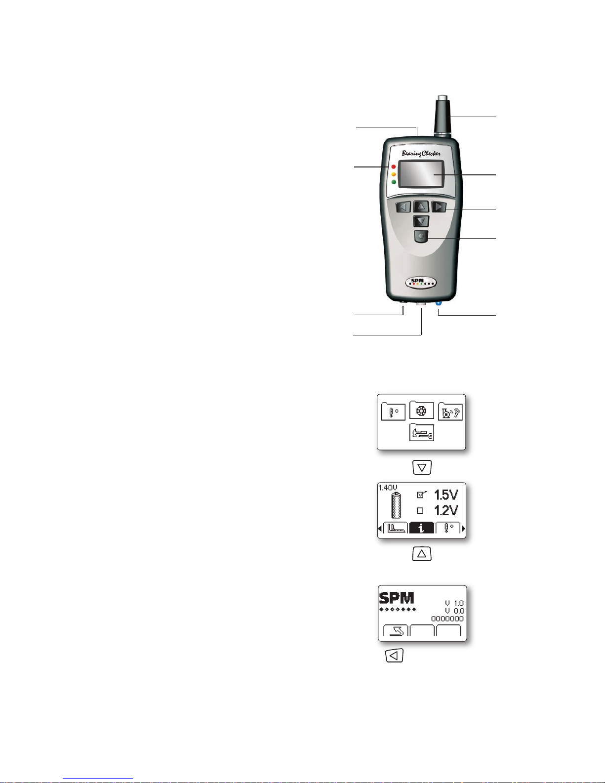
Instrument parts
1 Measuring probe
2 Temperature IR sensor
3 Condition indicators
4 Graphical display
5 Navigation keys
6 Measuring key and power on
7 Output for headphones
8 Transducer input
9 Measuring LED
10 Battery compartment
11 Serial number label
Instrument Overview
1
3
4
7 9
2
5
6
8
General description
The Bearing Checker is a shock pulse meter based on the well proven SPM method for quick and easy
identification of bearing faults. The instrument has a built-in microprocessor programmed to analyze
shock pulse patterns from all types of ball and roller bearings and display evaluated information on the
operating condition of the bearing.
Bearing Checker is battery powered and designed for use in harsh industrial environments. The graphic
display (4) gives the condition readings and the LED indicators (3) give an immediate evaluated bearing
condition in green-yellow-red.
The shock pulse transducer (1) of probe type is built-in. All types of SPM shock pulse transducers for adapters and permanent installation can also be used, connected to the transducer input (8). The dBi value is
programmed into the instrument and the measurement is started with key (6). The actual condition reading
is displayed on the graphical display (4) as a carpet value “dBc” and a maximum value “dBm”. The condition indicators (3) indicate the evaluated bearing condition in green-yellow-red. Headphones for listening
to the shock pulse pattern can be connected to the output (7).
The Bearing Checker can also be used for measuring surface temperature via the IR sensor (2), and for
detecting machine sound irregularities via headphones using the stethoscope function.
Internal or external probes can be used for listening.
11
10
Page 7

3
Displays and icons
Bearing measurement
Temperature
measurement
Stethoscope
function
General settings
Bearing measurement
Input data Measurement
Input dBi
MemoryTLT test Listening
Back/Return
Main display
Temperature measurement Stethoscope function
Measure (or press the probe tip)
Back/Return
Back/Return
Volume (1– 8)
Back
to main menu
Battery Unit
About
Temperature
General settings
Page 8
4
Pressing the measuring key (6) switches on the instrument.
Set up and measuring modes are selected with the arrow keys (5).
Measuring is started automatically whenever the internal
probe is pressed in. When using external probes, measuring is started manually by pressing the measuring key
(6) while in the Bearing mode.
The blue measuring LED (9) stops blinking when an SPM
measuring cycle is completed.
The green, yellow and red LEDs (4) beside the display
indicate the bearing condition after an SPM measurement.
If not used, the instrument will automatically shut off
after 2 minutes. It can also be shut off by simultaneously
pressing the LEFT and RIGHT arrow keys.
When switched back on, the instrument will resume its
last mode.
Start up
1
3
4
7 9
2
5
6
8
Serial number and software version
To check which software version is in your instrument
and find out the instrument serial number, go to the
Main display. Press the DOWN arrow key to enter the
General Settings mode. Use LEFT/RIGHT arrow keys
to highlight the Information icon (i), then press the UP
arrow key to see the software version and serial number.
To return to the General Settings mode, press the LEFT
arrow key.
To return to the Main display, use LEFT/RIGHT arrow
keys to highlight the Return icon, then press the UP
arrow key.
General
settings
Software version
and serial number
Back/Return
Main display
Page 9
5
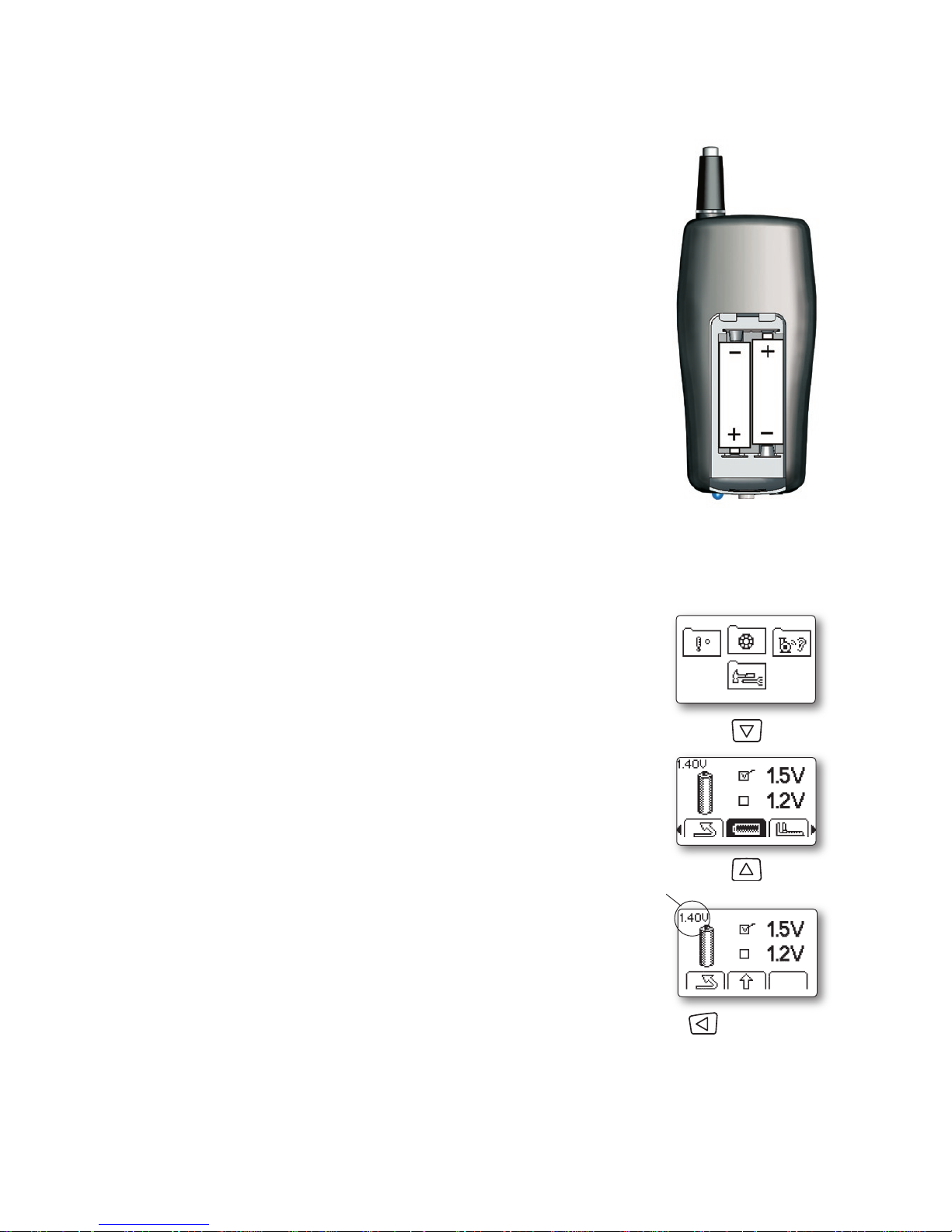
The instrument is powered by two batteries type MN 1500 LR6. Alkaline
or rechargeable batteries can be used. Please note that rechargeable
batteries must be removed from the instrument before recharging. The
battery compartment is located at the back. Press and push the lid to
open the compartment.
The battery test on the setup menu shows the present battery voltage.
The battery status icon will show when the batteries are low and have
to be replaced or recharged.
The battery life depends on how the instrument is used. Full power is
only consumed while a reading is in progress: from pressing the measuring key until a measured value is displayed.
Before long-time storage of the instrument, keep in mind to remove
the batteries.
Batteries
Battery check
For exact battery voltage, go to the battery setup menu:
From the Main display, press the DOWN arrow key to enter the General
Settings folder. Use LEFT/RIGHT arrow keys to highlight the battery icon,
then press the UP arrow key to enter battery type setup. The present battery voltage is shown in the upper left corner.
To return to the General Settings menu press the LEFT arrow key.
General
settings
Battery type
Battery
voltage
Back/Return
Main display
Page 10
6
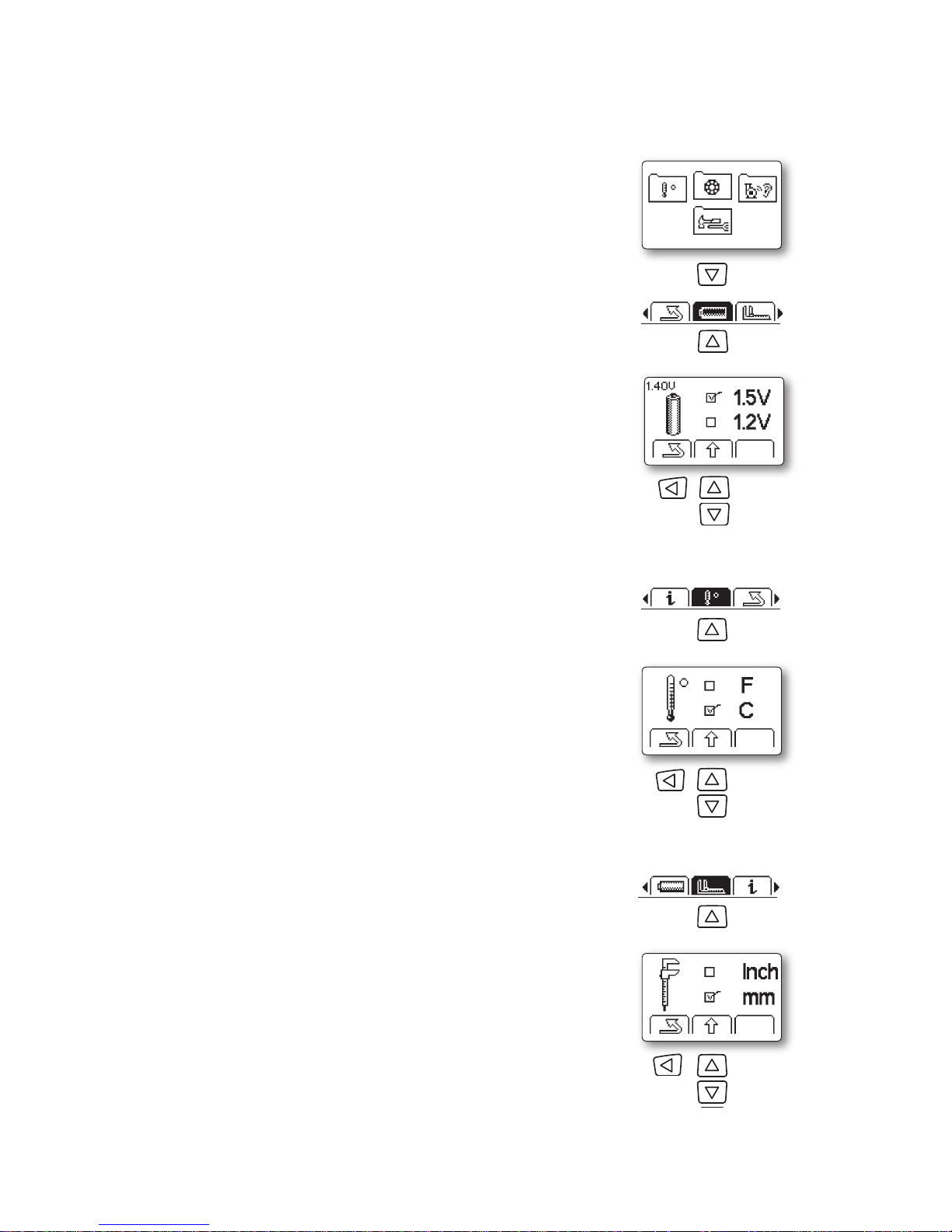
Battery type
Alcaline or rechargeable batteries can be used in Bearing Checker. The
battery type has no influence on instrument functionality or operation, but
should be set for the battery status icon to correctly show battery level.
From the Main display, press DOWN arrow key to enter the General Set-
tings folder. Use LEFT/RIGHT arrow keys to highlight the Battery icon,
then press the UP arrow key to enter battery type setup. Use UP/DOWN
arrow keys to set the battery type of your choice (1.2 V for rechargeable,
1.5 V for alcaline batteries). To save and return to the General Settings
menu press the LEFT arrow key.
To return to the Main display, use LEFT/RIGHT arrow keys to higlight the
Return icon, then press the UP arrow key.
Unit for temperature measurement
Temperature can be displayed in either Celsius or Fahrenheit. To choose
your unit of measurement, use the DOWN arrow key in the Main display
to enter the General Settings mode. Use the LEFT/RIGHT arrow keys
to highlight the Temperature icon, then press the UP arrow key. Use the
UP/DOWN arrow keys to set the measurement unit of your choice. To save
and return to the General Settings menu press the LEFT arrow key.
To return to the Main display, use the LEFT arrow key to highlight the
Return icon, then press the UP arrow key.
Unit for bearing diameter setting
Bearing diameter can be displayed in either mm or inch. To choose your
unit of measurement, use the DOWN arrow key in the Main display to
enter the General Settings mode. Use the LEFT/RIGHT arrow keys to
highlight the Measurement icon, then press the UP arrow key. Use the
UP/DOWN arrow keys to set the measurement unit of your choice. To save
and return to the General Settings menu press the LEFT arrow key.
To return to the Main display, use the LEFT arrow key to highlight the
Return icon, then press the UP arrow key.
Settings
Unit for temperature
General
settings
Select
type
Battery type
Back/Return
Main display
Select
inch or
mm
Unit for diameter
Select
°F or °C
Back/Return
Back/Return
Page 11
7
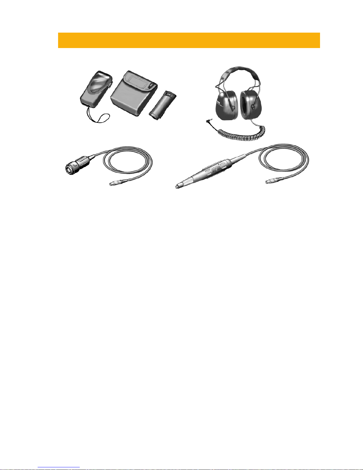
Accessories
Accessories
EAR12 Headphones with ear defenders
TRA73 External transducer with probe
TRA74 Transducer with quick connector for adapters
CAB52 Measuring cable with slip-on connector for permanently installed transducers, 1,5 m
15286 Belt holder for external probe transducer
15287 Belt case for accessories
15288 Protective cover with wrist strap
15455 Protective cover with belt clip and wrist strap
93363 Cable adapter, LEMO-BNC
93062 Cable adapter, BNC-TNC, plug-jack
Spare parts
13108 Rubber sleeve for probe tip, chloroprene, maximum 110 °C (230 °F)
15288
15455
15287 15286
EAR12
TRA74
TRA73
Page 12
8
The Shock Pulse Method
The Bearing Checker is based on the Shock Pulse Method. Measurements with the SPM method give an
indirect measure of impact velocity, i.e. the difference in velocity between two bodies at the moment of
impact. At the point of impact, a mechanical compression wave (a shock pulse) arises instantly in each
body. The peak value of the shock pulse is determined by the impact velocity and is not influenced by
the mass or the shape of the colliding bodies. Shock pulses in rotating ball and roller bearings are caused
by impacts between raceways and rolling elements. From the points of impact the shock pulses travel
through the bearing and the bearing housing. Extensive experience proves that there is a simple relationship between the bearing’s operating condition and the value of the shock pulses.
A transducer detects the shock pulses in the bearing. The transducer signals are processed in the bearing
detector’s microprocessor and the measured shock pulse values are shown on the display. An headphone
can be connected to the instrument for listening to the shock pulse pattern. Please note that this instrument cannot be used for plain bearings.
Shock pulses are short duration pressure pulses which are generated by mechanical impacts. Mechanical
impacts occur in all rotating rolling bearings because of irregularities in the surfaces of the raceways and
the rolling elements. The magnitude of the shock pulses depends on the impact velocity.
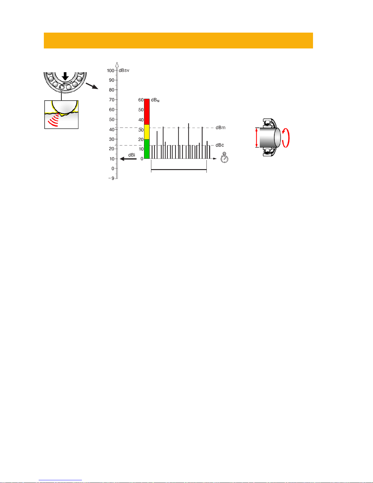
Carpet value dBc
Surface roughness (small irregularities) will cause a rapid sequence of minor shock pulses which together
constitute the shock carpet of the bearing. The magnitude of the shock carpet is expressed by the carpet
value dBc (decibel carpet value). The carpet value is affected by the oil film between rolling elements and
raceways. When the film thickness is normal, the bearing’s carpet value is low. Poor alignment and installation as well as insufficient lubrication will reduce the thickness of the oil film in the whole or parts of the
bearing. This causes the carpet value dBc to rise above normal.
Maximum value dBm
Bearing damage, i.e. relatively large irregularities in the surfaces, will cause single shock pulses with higher
magnitudes at random intervals. The highest shock pulse value measured on a bearing is called its maximum value dBm (decibel maximum value). The maximum value dBm is used to determine the operating
condition of the bearing. The carpet value dBc helps to analyze the cause of reduced or bad operating
condition.
Shock Pulse Measurement
dBi = Initial value of a bearing
dBc = Carpet value (weak pulses)
dBm = Maximum value (strong pulses)
dBn = Unit for normalized shock level
dBsv = Unit for absolute shock level
rpm
d
The initial value dBi
depends on rpm and
shaft diameter d.
2 seconds
Page 13

9
Normalized and unnormalized readings
The Bearing Checker measures impact velocity over a large dynamic range. In order to simplify readout
and evaluation, a logarithmic measuring unit is used: decibel shock value (dBsv).
dBsv is the general measuring unit for shock pulses. By measuring the shock pulses from a bearing in dBsv
a value for their magnitude is obtained, for instance 42 dBsv. However, this value is only part of the information needed to judge the operating condition of the bearing. We also need a standard of comparison,
i.e. a norm value for identical or similar bearings.
Such norm values have been obtained empirically, by measuring the shock pulses from a large number of
new, perfect ball and roller bearings. They are called “initial values” dBi (decibel initial). The dBi value can
be set manually or calculated by the instrument after input of rpm and shaft diameter (see chapter “Input
data”). The highest dBi value that can be entered is +60, the lowest -9. Any attempt to enter values below
this will result in dBi “- -” and an unnormalized shock pulse reading (see below).
By subtracting the dBi from the dBsv value we obtain the “normalized” shock pulse value or dBn (decibel
normalized) of the bearing, for example: 42 dBsv–10 dBi = 32 dBn”. The normalized shock pulse value dBn
is the measuring unit for the operating condition of bearings. A maximum value of 32 dBn means “32 dB
above normal”, which implies “reduced operating condition” for the measured bearing. By programming
the Bearing Checker with the dBi before taking a reading, the bearing condition will be indicated directly
on the condition display in green-yellow-red for “good”, “reduced” or “bad” operating condition for the
measured bearing. “Bad operating condition” can be synonymous with “bearing damage”, but the term
also includes a number of other “bearing faults” which can be detected by shock pulse measurement. The
initial value dBi of a bearing is directly related to its rotational speed and shaft diameter.
The absolute shock pulse level of a bearing, measured in dBsv (decibel shock value), is both a function of
rolling velocity and of bearing condition. The dBi value of the bearing must be entered in order to neutralize the effect of rolling velocity on the measured value.
The Bearing Checker takes a sample count of the shock pulses occurring over a period of time and displays:
• the maximum value dBm for the small number of strong shock pulses.
• the carpet value dBc for the large number of weaker shock pulses.
• a lit-up LED on the condition scale (for normalized readings only): green for dBn up to 20 dBn =
good condition, yellow for 21-34 dBn = caution, red for 35 dBn and more = bad condition.
The maximum value dBm defines the bearing’s position on the condition scale. The difference between
dBm and dBc is used for a finer analysis of the causes for reduced or bad condition.
Unnormalized readings
For unnormalized readings, set the dBi value to “- -” (see chapter “Input data”). You will then measure in
dBsv (absolute shock values) and get no condition indication, as the condition scale is graded in normalized shock values, dBn. This method is used for comparative readings on different bearings and/or other
shock pulse sources.
Page 14

10
The dBm/dBc technique
The dBm/dBc technique has been successfully applied for more than 35 years and continues to be widely
used. It is well suited for industrial condition monitoring, because it works with few, easy to understand
in- and output data.
Even on a logarithmic scale, there is normally a large, distinct difference between the maximum values
from good and bad bearings. Thus, minor inaccuracies in the input data (rpm and shaft diameter) have
little effect on the evaluated measuring result.
Lubrication condition is indicated by the delta value, i.e. the difference between dBm and dBc. High readings and a small delta value indicate poor lubrication or dry running. This is sufficient for maintenance
purposes.
dBm and dBc are measured in a fixed time window and automatically displayed.
The headphone is used to listen to the shock pulse pattern in case of suspect or high readings. This,
and the possibility to search for shock pulse sources with the probe transducer, are means to verify the
measuring result and its cause.
Life time
Page 15

11
The rules for the selection of SPM measuring points have a
very practical purpose. We are trying to capture low energy
signals which are getting weaker the farther they travel and
the more they are bounced about inside a piece of metal. We
know that they lose strength when they cross over from one
piece of metal to another. We cannot know, for all bearing
applications, how much of the strength of the signal emitted
by the bearing will reach the measuring point. However, by
necessity we try to apply general evaluation rules, i. e. treat
all measured signals as if they were of the same quality.
The rules for SPM measuring points try to assure that most
of them are ”within tolerance” and that the green-yellow-red
condition zones are valid:
1 The signal path between bearing and measuring
point shall be as short and straight as possible.
2 The signal path must contain only one mechanical
interface: that between bearing and bearing housing.
3 The measuring point shall be located in the load zone
of the bearing.
“Short” means up to 75 mm (3 in.), but that depends also
on how straight the path is: bends cause re- and deflections
whose effects are hard to judge. The load zone is the load
carrying half of the bearing housing, normally the lower one.
Allow for the pull of belts or other forces which can shift the
load to one side. Use the probe to find the spot yielding the
strongest signal. When a measuring point cannot conform to
the rules (because an ideal spot cannot be reached), make
allowance for a weaker signal.
Measuring
point
Load
1. Straight and short path
2. No interface!
3. In the load zone of the
bearing
Rules for measuring points
Page 16

12
The following two pages show measuring points and possible adapter or transducer installations. How to install
measuring equipment is described in the SPM installation
manual.
Through hole for long adapter
Figure A shows how a measuring point beneath a fan cover
can be reached with a long adapter, through a hole in the
cover.
Adapter with lock nut
In figure B, the fan cover is fastened directly to the motor shield, which is also the bearing housing. One of the
cover’s holding screws can be replaced by an adapter with
lock nut.
Bearing housings beneath brackets
Consult machine drawings and identify the bearing housing
before selecting a measuring point.
In figure C, showing a pump, the bearings are placed in two
separate housings inside the bearing bracket.
The bearing pair at measuring point 1 can be reached with
a long adapter through a clearance hole in the bracket. The
hole must be large enough to allow bearing adjustment
and still prevent metallic contact between bracket and
adapter.
Measuring point 2, placed below and opposite to the pump
outlet (load direction!) can be reached with a long adapter
through an opening in the pump shield.
Multiple bearings in one housing
If there are several bearings in the same housing, they are
normally treated as a single bearing. Figure D shows the
bearing arrangement for a vertical pump. It is not possible
to distinguish between the shock pulses from the paired
bearings in point 1.
There is also a risk for cross talk between point 1 and point
2, which means that the shock pulses from the bearing in
worst condition are picked up at both points. Check signal
strength with the probe. Use one measuring point only if
readings are identical in both points. This point (x) can be
placed halfway between points 1 and 2.
A
Measuring points, examples
1
2
C
B
D
Page 17

13
On large electric motors, the bearings are often mounted in
housings which are welded or bolted to the motor shields.
Because of the damping in the interface between the bushing and the shield, the measuring point should be on the
bushing.
The bearing housing at the drive end (A) is usually within
reach. A long adapter is installed at an angle to the shield, so
that there is enough space for connecting the transducer.
Installed transducer
The bearing at the fan end (B) requires a permanent transducer installation. The transducer is installed in the bushing.
The coaxial cable is run through a slit in the fan cover to a
measuring terminal on the stator frame.
Check installed equipment
Incorrectly installed adapters or transducers can cause a
significant damping of the shock pulse signal.
Check all installations. Make sure that mounting holes are correctly countersunk and that the seat surfaces of adapters have
good contact with the material of the bearing housings.
Any metallic machine part knocking or rubbing against the
adapter will produce a disturbance. This must be avoided by
making large clearance holes and using soft, elastic sealing
material.
Use high temperature cables and moisture proof equipment
where required, and protect installations against damage.
Adapters should be fitted with protective caps.
Mark the measuring points
Measuring points for the probe transducer should be clearly
marked. To get comparable readings, one must always use
the same measuring point.
A
drive end
A
B
B
fan end
Page 18

14
The measuring range of the Bearing Checker is large and
covers most bearing applications, but there are a few cases
where shock pulse monitoring should only be attempted with
installed measuring equipment, or not at all.
High speed bearings: The Bearing Checker accepts max.
19 999 rpm, 1 999 mm shaft diameter, and a dBi of 40. The
upper part of the table contains examples of possible combinations of shaft diameter and rpm giving a maximum dBi
of 40. The lower part of the table examplifies combinations
that give dBi = 0. The instrument calculates the dBi up to 40.
However, it is possible to manually set the dBi to max. 60. A
reason for setting dbi > 40 is when measuring on e.g. turbo
chargers, high speed gear boxes etc.
Low speed bearings: The lowest acceptable dBi is -9 dB.
However, it is nearly impossible to get a meaningful reading from bearings in the extremely low speed ranges. The
practical limit are bearings with a dBi around 0 dB (see lower
half of the table).
A heavy load with a well defined direction and a low interference level make it easier to get readings from low speed
bearings. Successful SPM monitoring has been carried out
on bearings with dBi = –3 (54 rpm, shaft diameter 260 mm).
Note that the dynamic measuring range decreases when dBi
values get below 0. For example, a bearing with dBi = –3
showed very heavy damages at dBn = 40.
Installed adapters required: The installation of adapters is
strongly recommended for all systematic shock pulse monitoring. In some cases it is a requirement:
• on bearings with dBi below 5
• on heavily vibrating bearing housings
• on covered bearing housings.
Low speed: Do not use a handheld probe on low speed
bearings. As a rule, the measurement should cover at least
10 full revolutions of the shaft. A single damaged part in the
raceway will cause a strong pulse only when hit by a rolling
element while passing through the load zone. It can take
several revolutions before that event occurs or is repeated.
Adapters required!
Covered
housing
dBi < 5
Heavy vibration
Shaft, mm rpm dBi
50 19 999 40
100 13 000 40
180 10 000 40
300 6 000 40
500 5 000 40
1 000 3 400 40
1 999 2 200 40
1 999 24 0
1 000 35 0
650 45 0
500 52 0
300 72 0
180 100 0
100 140 0
50 210 0
Measuring range
Page 19

15
The clicking of valves, high pressure steam flow, mechanical rubbing, damaged or badly adjusted gears,
and load shocks from machine operation can cause a general high shock level on the machine frame. This
interference can mask the bearing signal in cases where he shock level measured outside of the bearing
housings is as high or higher than the shock level on the bearing housings.
Remove sources of interference
In most cases, interference is the result of bad machine condition. For example – cavitation in a pump is
due to flow conditions for which the pump was not designed. Cavitation does more than interfere with
bearing monitoring – it slowly erodes the material of the pump.
Monitoring the bearings is pointless if the machine breaks down or requires frequent repairs because of
other poorly maintained parts or badly adjusted operating parameters. Therefore, do not accept interference – try to remove the cause.
Coping with interference
If the source of interference cannot be removed, there are several possibilities:
• If it is intermittent, measure while there is no interference.
If interference is persistent, measure its shock pulse level with the same dBi setting as the bearing and
compare it with the condition zones:
• If interference masks the green zone, you can get true bearing condition readings in the yellow and
red zone.
• If interference masks the yellow zone, you can get true bearing condition readings in the red zone,
i.e. find a damaged bearing.
If the interference level is persistently higher than the shock level that would be caused by bad bearing
condition (35 to 40 dB above the dBi), do not try to monitor the bearing.
Alignment
Scraping,
alignment
Cavitation
Gear tooth
damage
No interference Low level interference High level interference
Creating acceptable measuring conditions
Page 20

16
Unpredicted, very rapid damage development is rare. Normally, surface damage develops slowly, over
a period of many months. These are the general guidelines for selecting the interval between periodic
readings:
• The bearings should be checked at least once every three months.
• The bearings in critical machinery and heavily preloaded bearings (e.g. spindle bearings) should be
measured more often than other bearings.
• The bearings should be measured more frequently when their condition is unstable (rising or irregular readings).
• Damaged bearings should be closely watched until they can be replaced.
This implies that one has to allow time for extra checks on bearings in dubious or bad condition.
Check stand-by equipment
Vibration and corrosion can damage the bearings in stand-by machines. Check bearing condition each
time such machines are being tested or used.
Synchronize with lubrication
It may be necessary to synchronize regreasing and measuring intervals. Grease lubricated bearings should
not be measured until they have run for approximately one hour after regreasing (except when doing a
lubrication test).
Keep in mind that bad bearing condition is often connected with lubrication problems. For grease lubricated bearings, a lubrication test usually provides the final proof of bearing damage. Make sure that the
right type and quantity of grease is used.
Measuring personnel
should know about:
• lubricant type
• maximum quantity
• lubricating intervals
1-3 months
several days,
one week
measure
often
Measuring intervals
Page 21

17
Shock pulse transducers
Rubber sleeve in contact with
the surface
Point at the bearing
Hold steady
Built-in transducer with probe
Measuring points for the built-in probe should be clearly
marked. Always measure in the same spot. In addition, the
probe is used to measure elsewhere on the machine, in case
it is necessary to search for other shock pulse sources such as
pump cavitation or rubbing parts.
The probe tip is spring loaded and moves within a sleeve of
hard rubber. To maintain a steady pressure on the tip, press the
probe tip against the measuring point until the rubber sleeve
is in contact with the surface.
Hold the probe steady to avoid rubbing between probe tip
and surface.
The probe is directionally sensitive. It has to be pointed straight
at the bearing.
The centre of the probe tip should touch the surface. Avoid
pressing the probe tip against cavities and fillets which are
smaller than the probe tip.
Shock pulse transducer with handheld
probe
The handheld probe can be used to reach measuring points in
narrow spaces and has the same construction and method of
operation as the built-in transducer (see above).
The only part likely to wear out is the rubber sleeve for the
probe tip. It is made of chloroprene rubber (neoprene) and
tolerates 110° C (230° F). Spare sleeves have part number
13108.
Avoid small cavities and fillets
Transducer with probe
TRA73
Page 22

18
Transducer with quick connector
All types of shock pulse transducers are connected to the transducer
input (8). The choice of transducer type depends on how the measuring point is prepared. For systematic shock pulse monitoring, SPM
recommends the use of permanently installed adapters and quickconnect transducer wherever possible.
Adapters are solid metal bolts of different length and thread sizes,
tuned for correct signal transmission. They are installed in threaded,
countersunk mounting holes on the bearing housings. Glue-on adapters are available.
To attach the transducer with quick connector, press it against the
adapter and twist clockwise. Twist counter-clockwise to remove it.
Adapter surfaces must be clean and plane. Use an adapter cap to
protect them.
Check that installed transducers and adapters are properly mounted
(see the instruction on SPM installations) and in good condition. You
cannot expect a useful signal by attaching the quick connect transducer to a rusty lump of metal, or from a transducer that is rolling
on the floor on the other side of a partition.
Push and
twist
Installed
transducer
Measuring
terminal
Permanently installed transducers and
measuring terminal
A permanently installed transducer and a measuring terminal (BNC
or TNC connector) are used when the bearing cannot be reached
directly. Use a measuring cable to connect instrument and terminal.
Use SPM dust caps to protect the connector.
Check that installed transducers and adapters are properly mounted
(see the instruction on SPM installations) and in good condition. You
cannot expect a useful signal by attaching the quick connect transducer to a rusty lump of metal, or from a transducer that is rolling
on the floor on the other side of a partition.
TRA74
Standard
adapter
Standard
transducer
Page 23

19
Bearing Measurement
Input data
For a reading of bearing condition with Bearing Checker, you need
the initial value, dBi. If you do not know the bearing´s dBi, Bearing Checker will calculate and display the dBi given the rotational
speed (rpm) and the shaft diameter. Neglecting to enter this
information will produce incorrect measurement results.
Entering shaft diameter and rpm for dBi
calculation
From the Main display, press the UP arrow key to enter Bearing
mode. Use LEFT/RIGHT arrow keys to highlight the Input Data
icon, then press the UP arrow key. Use the LEFT/RIGHT arrow keys
to position the cursor and the UP/DOWN arrow keys to increase or
decrease the rpm value, respectively. To enter the shaft diameter,
first press the measuring key, then use the arrow keys to set the
diameter value the same way rpm was set.
Press the measuring key to return to Bearing mode.
Entering dBi manually
Changing the dBi directly is faster when you know it from your
records:
From the Main display, press the UP arrow key to enter Bearing
mode. Use LEFT/RIGHT arrow keys to highlight the dBi icon,
then press the UP arrow key. First, position the cursor using the
LEFT/RIGHT arrow keys, then use the UP/DOWN arrow keys to
increase or decrease the dBi value, respectively.
The highest dBi value that can be entered is +60, the lowest -9.
Any attempt to enter values below this results in dBi = “- -” and an
unnormalized shock pulse reading (see also chapters “Normalized
shock pulse values with dBi” and “Readings on gearboxes”). To
set the dBi value back from “- -” to “+” or “-”, press the UP arrow
key, then position the cursor as required to set the dBi.
Press the measuring key to return to Bearing mode.
The dBi value, whether calculated by the instrument or manually
input, is shown in the lower right part of the Bearing display.
shaft
diameter ø
rpm
Bearing
measurement
Enter rpm
OK
OK
Enter shaft diameter
Enter dBi value
OK
Page 24

20
For shock pulse measurement, press the UP arrow key in
the Main display to enter the Bearing display. Make sure
the shaft diameter and rotational speed of the bearing,
or its dBi, have been entered (se chapter Input data), or
the reading will be incorrect.
From the Bearing display, press the transducer to the meas-
uring point. Measurement starts automatically, taking a few
seconds, during which the blue measuring LED is lit up.
The two measuring results are the maximum value, dBm,
and the carpet value, dBc. Depending on the dBm value,
the green, yellow or red light LED to the left of the display
will light up.
When an external transducer is used, the instrument will
display a TLT warning sign if the transducer line test result
is unsatisfactory. To see the TLT value for the latest reading, go to the TLT menu. For further information about TLT,
please see chapter “Transducer Line Test”.
When measurement is finished, the LED indicators show
the bearing condition, and an evaluation code is displayed.
The code refers to the Evaluation Flow Chart on page 3233, which must be used to further evaluate the bearing
condition.
When you get high readings (yellow and red zone), you
should immediately verify their nature and probable cause.
Do not give the verdict ”bearing damage” before making
a further investigation. As a first measure:
• use the headphones to identify the shock pulse pattern.
• measure on and outside of the bearing housing to
identify the shock pulse source.
Surface temperature is measured automatically when an
SPM measurement is made. To see the temperature reading, use LEFT/RIGHT arrow keys to activate the Return
icon in the Bearing display, then press the UP arrow key to
enter the Main display. Press the LEFT arrow key to enter
Temperature mode and see the reading. To return to the
Main display, press the LEFT arrow key.
Shock pulse measurement
Condition indicators:
red - bad (≥35)
yellow - caution (21–34)
green - good (≤ 20)
Check:
- Shaft diameter and rpm, dBi setting
- Measuring point in the load zone
- Probe pointed straight at the
bearing
- Adapter (transducer) properly
mounted
- Adapter surface clean, undamaged
- Quick connect transducer firmly
attached
Bearing measurement
Evaluation
code
Measure
(or press the
probe tip)
TLT warning
Page 25

21
Transducer Line Test
When measuring shock pulses with external transducers, a
transducer line test (TLT) will automatically be made to check
the quality of the signal transmission between transducer and
instrument (the TLT value for the latest reading is always saved
and is shown in the TLT window). Part of your signal will be
lost in a poor transducer line, so your measuring results will
be lower than they should be. If an SPM measurement is made
with a poor transducer line, the instrument will display a TLT
warning sign.
To perform a transducer line test (TLT) manually, connect the
external transducer to the instrument. From the Main display,
press the UP arrow key to enter the Bearing folder, then use
LEFT/RIGHT arrow keys to highlight the TLT icon. Press the
UP arrow key to enter the TLT menu. Press the measuring key
briefly. The blue measuring LED lights up and the reading is
shown in the display.
The TLT test window also displays transducer type: IPR (internal
probe), EPR (external probe), TRA (40000 type) or TMU (42000
type). TRA is also displayed in case of a cable breakdown. The
TLT value then depends on the distance to the breakage point
(1-2 dB/meter). In case of a shortcircuit, TMU and the value 0
(normally) is displayed.
At TLT values from 15 upward, there is normally no signal loss
due to poor transmission between transducer and instrument.
If the value is below 15, or if it is deteriorating from a previously higher value, you need to check cables, connectors and
transducers for poor connections and moisture.
The TLT test can be temporarily turned off to force evaluated
measurement results on transducers with TLT below 15, e.g.
when measuring via coupling transformers. In the TLT menu,
press the RIGHT arrow key to turn the test off. The TLT test is au-The TLT test is automatically turned back on by entering the TLT menu again and
when the instrument is automatically or manually turned off.
Storing measurement results
This function is useful for easy comparison of measurement
results for a particular measuring point. It can also be used to
store measurement results temporarily until they can be recorded on paper for trending and follow-up. On the last page
iof the User Guide is a follow-up form which can be copied and
used for this purpose.
The Bearing Checker can store up to ten SPM measurement
results.
In the Bearing display, use LEFT/RIGHT arrow keys to highlight
the Memory icon, then press the UP arrow key to enter Memory
mode. Select memory place (1-10) by using the UP/DOWN arrow keys. Press the RIGHT arrow key to store the reading. This
action will overwrite any previously stored value in the memory
place selected.
To return to the Bearing display, press the LEFT arrow key.
Latest reading
Stored reading
Current memory place
dBi
Transducer Line Test
Bearing measurement
Measure
TLT
Save
Select place
Memory
Bearing measurement
TLT off
Page 26

22
The stream of shock pulses from a rotating bearing is continuous. They vary in strength, depending on the relative
positions of rolling elements and raceways.
The headphone is a means to verify and trace shock pulse
sources. The headphones allow you to listen to the shock
pulse pattern. In the headphone, the noise carpet is represented by a continuous tone. The dBc level is approximately
where you can start to distinguish between an even sound
and individual pulses. Typical for bearing signals is a random
sequence of strong pulses with no discernable rhythm, best
heard a few dB below the dBm level.
A spot of surface damage causing a strong shock pulse will
only register, if a roller hits it during the measuring interval.
Especially at low rotational speeds, the instrument can miss
the strongest pulse, simply because it does not occur during
the measuring interval.
To listen to the shock pulse pattern after taking an SPM
reading, connect your headphones to the output connector
(7). From the Main display, press the UP arrow key to enter
Bearing mode. Use the LEFT/RIGHT arrow keys to highlight
the Listening icon, then press the UP arrow key to enter
listening mode, where the dBm value of the latest reading
is displayed. Use the UP/DOWN arrow keys to adjust the
amplitude level at which you wish to listen; anything below
this value will be filtered out.
To adjust the headphone volume use the RIGHT arrow key.
NOTE! Setting the volume to the maximum level may harm
your hearing.
To return to the Bearing display, press the LEFT arrow
key.
Headphones
dBn
Listening to the shock pulse pattern
Adjust
amplitude
level
Headphone volume
Adjustment of
amplitude level
Listening
Adjust
volume
Back
Bearing measurement
Page 27

23
NOTE! A reading taken with an incorrect dBi value causes an incorrect evaluation of the bearing condition! Always check that the correct dBi for the bearing in question has been entered!
Evaluation simply means that you make sure that the information you pass on to the maintenance personnel is as correct as possible and as detailed as necessary. Always remember that
• some machines can contain many types of shock pulse sources other than the bearing, and
• there can be a number of different causes for bad bearing condition other than damage.
Evaluation requires only normal care and common sense. Use the probe transducer and the headphone,
and also use your senses: look, touch, listen. By being thorough you can avoid raising false alarms or
missing damaged bearings.
Initial readings and changes
There are only two situations where an evaluation is necessary. The first is when you start with bearing
monitoring:
• Always evaluate the first readings on new measuring points and newly installed bearings.
The purpose is to establish a reliable base for routine measurements. You want to be quite sure that you
are measuring shock pulses from the bearing and that the reading itself is correct. If you find that bearing
condition is good, you do not have to evaluate the following readings on that measuring point as long as
there is no significant change.
The other situation is when you notice a change in the readings (or get high readings from the start):
• Investigate any significant increase or decrease of the shock pulse level.
Again, you want to be quite sure that you are measuring shock pulses from the bearing and that the reading itself is correct.
If you find that bearing condition is not good, you have to distinguish between bad installation, poor
lubrication, overload and damage, in order to decide what kind of maintenance work is needed. If you
are getting an interference signal, it is probably caused by machine faults which have to be reported and
repaired.
Machine Bearing Bearing Bearing
alignment lubrication installation damage
High maximum value
Interference
Cross talk from
other bearings
Interference from
mechanical shocks
Operating condition not good
Evaluating the Bearing Condition
1 Reading correct ? Check!
Measuring point? Installation ? Correct dBi ?
dBm?
Look, feel, check data.
2 Shock pulse source? Search!
Bearing ? Interference? Signal pattern? Loose
parts?
Look, listen. Use probe transducer, headphone
.
3
Bearing fault? Analyse!
Lubrication? Alignment? Installation?
Bearing damage?
Identify shock pulse pattern.
Check trend. Test lubrication.
Page 28

24
Sources of interference
Any kind of metallic clatter, hard impacts or scraping produces shock pulses which may interfere with the
measurement on the bearings. Some of the more common sources of interference are:
• Shocks between poorly fastened machine feet and foundation.
• Rubbing between shafts and other machine parts.
• Loose parts striking the machine frame or the bearing housing.
• Excessive play and misalignment of couplings.
• Vibration in connection with loose parts and excessive bearing play (vibration alone does not affect
the reading).
• Cavitation in pumps.
• Gear tooth damage.
• Load and pressure shocks arising during the normal operation of certain machines.
Identifying the shock pulse source
Excessive
play
Gear tooth
damage
Cavitation
Play,
scraping
Shock pulses are strongest close to the source. They spread through the material of all machine parts, but
are dampened (loss of signal) with distance and when passing through interfaces in the material.
• Measure on and near the bearing housing to find the strongest shock pulse source.
• Listen for unusual noises.
Page 29

25
The headphone is a means to verify and trace shock pulse
sources. The signal from a bearing should be highest on the
bearing housing. If you get a higher signal outside of the
bearing housing (across an interface in the material), you are
most likely measuring shock pulses from another bearing
or some other source. Typical for bearing signals is that the
stronger shock pulses, best heard a few dB below the peak
level, appear at random intervals.
The codes refer to the Evaluation Guide, or the Flow Chart
on page 32-33, which must be used to further evaluate the
bearing condition.
If instrument displays “2/3” or “4/5”, use the headphones
to determine the condition code.
1 For a good bearing, the dBm is within the green zone.
dBm and dBc are close together.
2 The shock pulse pattern from a damaged bearing contains strong pulses in the red zone, a random sequence, and
a large difference between dBm and dBc. When you lubricate the bearing, the values should drop but rise again.
3 A dry running bearing has a high carpet value very close
to the dBm. When you lubricate the bearing, the values
should drop and stay low. A similar pattern is caused by
pump cavitation, in which case readings on the pump housing are stronger than those taken on the bearing housing,
and are not influenced by lubricating the bearing.
4 A regular pattern, containing bursts of strong pulses in
a rhythmic sequence, is caused by e.g. scraping parts.
5 Individual pulses in a regular sequence are cause by clicking valves, knocking parts, regular load shocks.
6 A sudden drop in the shock pulse level is suspicious.
Check your measuring equipment. If the reading is correct,
you may have a slipping bearing ring.
Shock pulse patterns – condition codes
Page 30

26
A) Maximum value dBm
B) Difference between dBm and dBc
C) Rhythm of the strongest pulses
A shock pulse pattern is a sequence of either random
or rhythmical strong pulses (dBm level) above a carpet
of very rapid weaker pulses (dBc level). You have to be
aware of:
• the dBm value
• the difference between dBm and dBc
• the rhythm of the strongest pulses.
The rhythm of the strongest pulses is best discerned by
listening with the headphone at a setting a few dB below
the dBm level. Typical for bearing signals is a random
sequence of strong pulses (no discernable rhythm).
Rhythmical shocks can come from a bearing but are
more often a sign of interference. Typical patterns are
described on the next pages.
The Bearing Checker recognizes the pattern of the
reading taken and determines which of the six patterns
below is a match. The matching number is displayed in
the upper left corner of the Bearing display when the
measurement is completed. This number corresponds
to the pattern numbers below.
There may be times when the instrument displays a
combination of the numbers “2/3” or “4/5”, in which
case the instrument can not distinguish between the two
codes. Use the headphones and listen to the pattern to
determine condition code.
1 Pattern from a good bearing
A bearing in good condition should have a dBm value
below 20 and a dBc value approximately 5 to 10 dB lower.
Once you have verified the reading, there is no need for
any further evaluation.
The maximum value can be lower than 0. However, be
suspicious when the measured value is very low. The
cause is often a bad measuring point or an incorrectly
installed adapter or transducer. If the reading is very
low, check the installation. Measure on other parts of
the bearing housing and try to pick up a stronger signal.
Another possible reason for a very low reading is that
there is no load on the bearing. This can happen with well
balanced fans and similar rotating machines.
Typical shock pulse patterns from rolling bearings
A
B
C
dBm
dBc
Evaluation code
Page 31
27
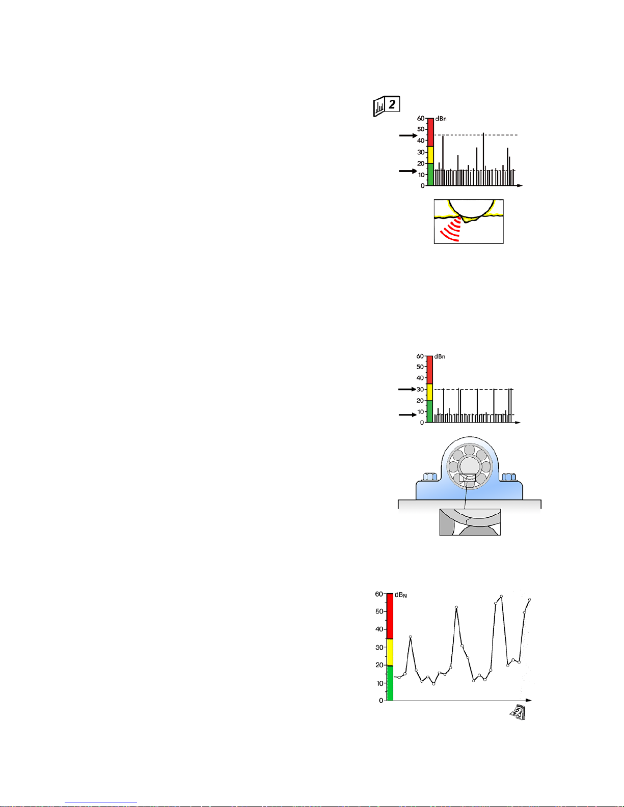
2 Signal from a damaged bearing
The pattern shown is typical for damaged bearing surfaces:
a dBm above 35 dB, a large gap between dBm and dBc,
and a random pattern of strong pulses. The strength of the
maximum value dBm indicates the degree of damage:
35 – 40 dBN Slight damage
40 – 45 dB
N
Severe damage
> 45 dBN High breakdown risk.
First signs of damage
dBm values between 20 and 35 dB (in the yellow zone)
and a moderate increase of the carpet value are a sign of
stress in the bearing surfaces or minor damage. Note that
the gap between dBm and dBc gets larger.
Bearings with dBm values in the yellow zone should be
measured more frequently, to determine if their condition
is stable or deteriorating.
Note: a similar pattern is caused by contaminations in the
lubricant (metal or dirt). The particles either originate from
parts of the bearing itself, for instance from a damaged
cage, or they are transported by the lubricant into the
(undamaged) bearing. Test bearing and lubricant according to the description “Confirming bearing damage” in
this manual.
Cracked inner ring
A clean crack in the inner ring of a bearing is difficult to
detect, especially at a low rpm. You may get low readings
through most of the bearing’s rotation, then one or two
peaks while the crack is in the load zone. Signal strength
can differ considerably as the crack opens or closes depending on bearing temperature. In time, the surface
tends to spall along the crack, leaving sharp edges and
metal particles which cause high shock values until they
are rolled out.
dBm
dBc
dBm
dBc
Irregular measuring results
Large variations between consecutive readings are a danger sign. Damaged bearings do not improve with time,
although their shock values may temporarily drop.
Make sure the measuring interval is established according
the variations in production load (e.g. air compressors).
Always measure under the same production conditions.
Wide variations in the readings taken at different times
can occur on heavily loaded roller bearings with surface
damage. The high readings are caused by metal particles
breaking off the surfaces and by the sharp edges of new
spallings. When particles and edges are rolled out, the
readings will drop again.
Page 32

28
3 Patterns from poorly lubricated bearings
A high carpet value, very close to the maximum value, is
typical for dry running bearings. The dBm does not always
reach the red zone – typical for poor lubrication is that
the gap between dBm and dBc is very small. If the signal
is strongest on the bearing housing, it can have several
causes:
• insufficient lubricant supply to the bearing (poor oil
flow; old , caked, or cold grease)
• very low or very high bearing speed (preventing the
build-up of an oil film separation between the loaded
rolling elements and the raceway)
• installation fault (excessive preload) or out-of-round
bearing housing
• misalignment or bent shaft.
If possible, lubricate the bearing or increase the oil flow.
Measure immediately afterwards, and again a few hours
later. If the problem was insufficient lubricant supply, the
shock pulse level should drop and stay low.
In the case of very low or very high bearing speed, one
can try lubricants of a different viscosity or use additives
to prevent metal to metal contact between the bearing
surfaces.
In cases of installation faults, unround housings, and misalignment) the shock pulse level may drop after lubrication
but will soon rise again. Misalignment normally affects the
bearings on both sides of the coupling or at both ends of
the shaft.
Cavitation and similar interference
The shock pulse pattern caused by a cavitating pump or by
persistent rubbing is identical with that from a dry running
bearing. You have an interference signal when the shock
pulse level is highest outside of the bearing housing and
is not affected by lubricating the bearing.
If you cannot remove the cause of interference, you have a
“blind spot”: up to a certain level, the interference signal
will mask the signal from one or more bearings. However,
you may still be able to detect bearing damage. When the
dBm rises above the interference level, it must be caused
by something else – probably bad bearing condition. In
that case, lubricating the bearing should cause the value
to drop, at least temporarily.
Cavitation
Poor lubrication
dBm
dBc
Page 33

29
6 Large drop in the readings
If the shock pulse level drops after a sequence of
normal readings, you have either a malfunction of the
instrument, a failure in a transducer installation, or a
serious bearing fault.
Check the instrument by measuring on some other
bearing. In case of an installed transducer, try to get
a reading by tapping on the bearing housing. If your
reading is correct, it is possible that one of the bearing
races is slipping, either on the shaft or in the housing. In
case of a heavily loaded bearing with previous readings
in the red zone, suspect cage failure.
dBm
dBc
dBm
dBc
5 Rhythmical peaks
Single, rhythmical peaks can be caused by load and
pressure shocks which occur during the machine’s
normal operation. Other possible causes are clicking
valves or loose parts knocking regularly against the
machine frame.
If the signal is strongest on the bearing housing, you
can suspect a cracked inner ring.
4 Periodic bursts
Periodic bursts are a typical interference signal, caused
by rubbing between machine parts, e.g. shaft against
bearing housing or seal. The burst occurs at an rpm
related frequency.
Page 34

30
On receiving the typical bearing damage signal – high dBm, large
difference between dBm and dBc, random peaks, strongest signal
on the bearing housing – you must confirm one of the following
causes for the reading:
• tapping of loose parts against the bearing housing
• excessive bearing play in combination with vibration
• particles in the lubricant
• bearing damage.
Interference can usually be detected by a careful inspection.
Lubrication test
A lubrication test is the best means to reach a conclusive verdict:
• Make sure that the lubricant is clean and not contaminated.
• Lubricate the bearing and repeat the measurement. Meas-
ure immediately after lubricating and again a few hours later.
Make sure that the lubricant reaches the bearing. Typically, you
will get the following results:
A The shock pulse level remains constant. The signal is caused
by interference or cross talk from another bearing.
B The shock pulse level drops immediately after lubricating
and remains low. Foreign particles in the bearing were removed by the fresh lubricant.
C The shock pulse level drops immediately after lubricating
but rises again within a few hours.
The bearing is damaged.
Note that metal particles in the lubricant can originate from the
bearing itself. Measure the bearing again over the next few days
and make sure that the values stay low.
Confirming bearing damage
Page 35

31
Shock pulses can sometimes spread through a machine
housing without significant damping. This means that the
shock pulses from the bearing with the highest shock
pulse level can, under unfavourable circumstances, interfere with the readings on all the other bearings.
The problem is aggravated when the bearings are of different sizes and rotating at different speeds, as in a gear
box. A bearing with high rotational speed has a high dBi
value and generates relatively strong pulses even when
its operating condition is good. The same shock pulse
level measured on a bearing with a low dBi may indicate
bad bearing condition.
In such cases, you must proceed as follows:
1 Take a reading with dBi set to “--” on all bearings.
This will reveal the strongest shock pulse source on
the machine. In the example in the figure, you get
a reading of 53 dBsv for bearing A and 47 dBsv for
bearing B.
NOTE! When taking readings with dBi set to “--”
the evaluation in green - yellow- red does not
apply! See also chapters “Normalized shock pulse
values with dBi” and “Input data”.
2 Work out the direction of possible cross talk. You
know that the stronger source can mask the signal
of the weaker source. In this case, cross talk must
go from bearing A to bearing B.
3 Subtract the dBi values from the dBsv values. In the
example, you get 26 dBN for bearing A, 40 dBN for
bearing B.
You can now draw two conclusions: The reading for
bearing A, coming from the stronger source, is probably
accurate. The bearing condition is reduced (26 dB = yellow zone) but not seriously so.
The reading from bearing B is either true or false. If true,
it indicates bad bearing condition (40 dB = red zone), but
you cannot confirm that with the instrument before condition gets worse and bearing B becomes the stronger
shock pulse source. Your solution is to take frequent
readings and compare the results from both bearings.
1 Readings with dBi = “--” reveal
the stronger source
3 The reading from the
stronger source is
normally accurate
The reading from the
weaker source cannot
be confirmed
Cross talk !?
2 Cross talk must go from the
stronger to the weaker source
Readings on gear boxes
Page 36

32
Evaluation flow chart
On the
bearing
housing
Where
do you
get the
highest
reading?
Adjacent to
the bearing
housing
On the
bearing
housing
Locate the signal source.
Probable causes:
• Load or pressure shocks from equipment installed on
the machine frame.
• Other mechanical shocks from the machine’s operation
If possible, isolate the source of disturbance and test
again.
Probable causes:
• Load or pressure shocks in the machine’s operation
causing mechanical shocks in the bearing.
• Individual gear tooth damage
• Bearing damage
Probable causes:
• The shaft rubs against the bearing housing or the end of
the shaft rubs against the bearing cap.
• Gear tooth damage
• Other mechanical rubbing
Newly installed bearing?
Locate the signal source. The reading can be caused by
interference from other defective bearings, cavitation
in pumps or mechanical rubbing. If possible, isolate the
source of disturbance and test again.
Locate the signal source. If possible, isolate the source of
disturbance and test again.
Adjacent to
the bearing
housing
Check the value of adjacent bearings.
Are the signals from these bearings similar to the tested
bearing?
Locate the signal source. The reading can be caused by
cross talk from other defective bearings or disturbances
from other mechanical shocks. If possible, isolate the
source of disturbance and test again.
Adjacent to
the bearing
housing
On the
bearing
housing
Where
do you
get the
highest
reading?
Adjacent to
the bearing
housing
Where
do you
get the
highest
reading?
On the
bearing
housing
No signal or only a very low value can be obtained.
Where
do you
get the
highest
reading?
Good bearing condition, installation and lubrication.
Page 37

33
Probable causes: axial shocks, load shocks, defective shaft coupling, gear tooth damage, cross talk
from other defective bearings.
If possible, lubricate
the bearing and
check the reading at
the same time.
When lubricating,
check that the lubricant penetrates into
the bearing.
No
The reading does not drop.
Probable causes: disturbances from loose bearing cap,
protecting cover or similar items.
Can also be caused by: Large bearing damage.
The reading drops to normal level and does not increase
again. Cause: foreign particles in the bearing which have
been removed by the new lubricant.
Have normal values
been previous observed?
NOTE: Be suspicious
when sudden drastic
changes in readings
occur.
Probable causes:
• Insufficient lubrica
tion, possibly in
com-bination with
minor bearing damage
• Cavitation in pumps
• Mechanical rubbing
• Gear tooth damage
Yes
Probable causes:
• Bearing damage.
Measure in shorter
in-tervals, follow the
pro-gress of the damage .
• Foreign particles in
the lubricant.
Can also be caused by
disturbance from loose
bearing cap, protecting cover or similar
items.
If possible, isolate the
source of disturbance
The reading drops to normal level and does not increase
again. Cause: insufficient lubrication.
The reading does not drop.
Probably causes:
• Cavitation in pumps
• Mechanical rubbing
• Gear tooth damage
The reading drops but the max. value increases again
within a few hours.
Probable causes: insufficient lubrication which probably
has caused minor bearing damage.
The reading does not drop.
Probably causes:
• Incorrect bearing installation
• Cavitation in pumps
• Mechanical rubbing
• Gear tooth damage
The reading drops but the dBm increases again within a
few hours.
Probable causes: insufficient lubrication which probably
has caused minor bearing damage.
The reading drops to normal level and does not increase
again. Cause: insufficient lubrication.
Probably causes:
• The bearing’s inner ring is slipping on the shaft.
• The bearing’s outer ring is slipping in the housing.
• The reading has been taken just after lubricating a
grease lubricated bearing.
If possible, lubricate
the bearing and
check the reading at
the same time.
When lubricating,
check that the lubricant penetrates into
the bearing.
Probable causes:
• Incorrect bearing
installation
• Insufficient lubrica
tion possibly in combination with minor
bearing damage
• Cavitation in pumps
• Mechanical rubbing
• Gear tooth damage
Yes
No
If possible, lubricate
the bearing and
check the reading at
the same time.
When lubricating,
check that the lubricant penetrates into
the bearing.
Yes
• Is the instrument and the
transducer working ok?
• Is the measuring point cor
-
rect?
• Is the adapter or the trans
-
ducer correctly installed?
• Is the machine in operation?
The reading drops but increases again within a few hours.
Cause: bearing damage.
Shorten measuring intervals to follow the progress of the
damage.
Page 38

34
Temperature measurement is carried out with a contact-free infrared
sensor (IR). The sensor is placed on top of the instrument, next to the
probe transducer.
The window of the sensor is covered with a filter for infrared radiation.
If the window is covered or smudged with some other material, e.g.
water, the sensor will not be able to detect the correct amount of radiation and the instrument will therefore give an incorrect reading.
A polished metal surface emits less radiation than a painted surface.
If you want to measure on a polished metal surface, you may have
to attach a paper label or paint the surface to get a correct reading.
Also, bear in mind that a blank surface may reflect heat radiation from
surrounding objects.
Emissivity of some common materials:
Brass, polished 0,03
Brass, oxidized 0,61
Copper, roughly polished 0,07
Copper, black, oxidized 0,78
Paint, varnish, black 0,96
Aluminum foil 0,09
Lead, oxidized 0,43
Iron, corroded 0,78
Iron, oxidized 0,84
The viewing angle of the sensor is 60 degrees, giving a measuring
area of 36 mm diameter at the distance of the probe tip and 115 mm
at a 10 cm distance.
To measure temperature:
From the Main display, press the LEFT arrow key to enter Temperature
mode. Hold the probe tip against the surface you wish to measure
and press the measuring key to get a temperature reading. For most
accurate results, take two consecutive readings a few seconds apart.
Measurement will continue as long as the measurement key, or the
probe tip, is being pressed.
To return to the Main menu, press the LEFT arrow key.
NOTE: If you are using an optional transducer for shock pulse
measurement, measure temperature manually (see instructions in
paragraph above).
Machine surface temperature is also measured automatically when an
SPM measurement is made:
To see the temperature reading after an SPM measurement, use
LEFT/RIGHT arrow keys to activate the Return icon in the Bearing
display, then press the UP arrow key to enter the Main display. Press
the LEFT arrow key to enter Temperature mode and see the reading.
The value presented is always the latest reading, whether automatically or manually (see above) measured. To return to the Main display,
press the LEFT arrow key.
Temperature Measurement
Measurement area
Temperature measurement
Measure
Measurement
indicator
Back/
Return
Page 39

35
The stethoscope function is useful for detecting machine
sound irregularities, such as load shocks and scraping.
Connect your headphones to the output connector (7).
From the Main display, use the RIGHT arrow button to
enter the Stethoscope mode. Hold the probe tip against
the object. Use UP/DOWN arrow keys to adjust the
volume (1-8).
NOTE! Setting the volume to the maximum level may
harm your hearing.
To return to the Main display, press the LEFT arrow
key.
Using the Stethoscope Function
Stethoscope function
Volume (1–8)
(7)
Back/Return
Page 40

36
Technical Specifications
Material, casing: ABS/PC
Size: 158 x 62 x 30 mm
(6.2 x 2.4 x 1.2 in)
Weight: 185 g (6.5 ounces) including battery
Keypad: Sealed membrane (silicone rubber)
Display: Graphic monochrome, 64 x 128 pixels, LED backlight
Bearing condition indication: Green, yellow and red light LEDs
Measurement indication: Blue light LED
Power supply: 2 x 1.5 V AA batteries, alkaline or rechargeable
Battery life: > 20 hrs of normal use
Operating temperature: 0 to +50°C (32 to 122°F)
Input connector: Lemo coaxial, for external shock pulse transducers (probe or
quick connector)
Output connector: 3,5 mm stereo mini plug for headphones
General functions: Battery status display, transducer line test, metric or Imperial
units of measurement, language independent menus with
symbols, storage of up to 10 measurement values
Shock pulse measurement
Measurement technique: dBm/dBc, measuring range -9 to 90 dBsv, +3 dBsv
Transducer type: Built-in probe transducer
Temperature measurement
Temperature range: –10 to +185 °C (14 to 365°F)
Resolution: 1 °C (1°F)
Transducer type: Thermopile Sensor TPS 334/3161, built-in contact free IR-sensor
Stethoscope
Headphone mode: 8 level amplification
Article no.
BC100 Bearing Checker
Accessories
EAR12 Headphones with ear defenders
TRA73 External transducer with probe
TRA74 Transducer with quick connector for adapters
CAB52 Measuring cable with slip-on connector for permanently installed transducers, 1,5 m
15286 Belt holder for external probe transducer
15287 Belt case for accessories
15288 Protective cover with wrist strap
15455 Protective cover with belt clip and wrist strap
93363 Cable adapter, LEMO-BNC
93062 Cable adapter, BNC-TNC, plug-jack
Page 41

37
An instrument calibration, e.g. for the purpose of compliance with ISO quality standard requirements, is
recommended once a year. Please contact your SPM representative for service, upgrading the software
or calibration.
Maintenance and calibration
EU Directive on waste electrical and electronic equipment
WEEE is EU Directive 2002/96/EC of the European Parliament and of the Council on waste electrical
and electronic equipment.
The purpose of this directive is, as a first priority, the prevention of waste electrical and electronic
equipment (WEEE), and in addition, the reuse, recycling and other forms of recovery of such wastes so
as to reduce the disposal of waste.
This product must be disposed of as electronic waste and is marked with a crossed-out wheeled bin
symbol in order to prevent it being discarded with household waste.
Once the life cycle of the product is over you can return it to your local SPM representative
for correct treatment, or dispose of it together with your other electronic waste.
Page 42

40
50
30
20
10
dB
N
40
50
30
20
10
dB
N
40
50
30
20
10
dB
N
M
40
50
30
20
10
dB
N
dB
dB
C
dB
i
d
n
M
dB
dB
C
dB
i
d
n
d
dB
i
n
M
dB
dB
C
dB
i
dB
M
dB
C
d
n
. . . . . . . . . . . . . . . . . . . . . . . . . . . . . . . . . . . . . . .
. . . . . . . . . . . . . . . . . . . . . . . . . . . . . . . . . . . . . . .
. . . . . . . . . . . . . . . . . . . . . . . . . . . . . . . . . . . . . . .
. . . . . . . . . . . . . . . . . . . . . . . . . . . . . . . . . . . . . . .
. . . . . . . . . . . . . . . . . . . . . . . . . . . . . . . . . . . . . . .
. . . . . . . . . . . . . . . . . . . . . . . . . . . . . . . . . . . . . . .
SPM Follow-up form
 Loading...