

Page 1

Smart Voltmeter
User Manual
Multifunctional Digital Car Voltmeter with Protection Feature
2014
SPL-Laboratory
01.01.2014
Page 2

2
Table of Contents
Table of Contents ............................................................................................................................ 2
Functions and technical features of the device ................................................................................ 3
Description ................................................................................................................................... 3
Ergonomics .................................................................................................................................. 4
Technical features ........................................................................................................................ 5
Working with the device.................................................................................................................. 6
Important safety information: ...................................................................................................... 6
Identifying the functional parts of the device: ............................................................................. 7
Number of the element ................................................................................................................ 7
Description ................................................................................................................................... 7
Functional purpose of slot contacts.............................................................................................. 7
Number of the element ................................................................................................................ 7
Description ................................................................................................................................... 7
Typical device connection schemes ............................................................................................. 8
Contact ......................................................................................................................................... 8
Description ................................................................................................................................... 8
Contact ......................................................................................................................................... 8
Description ................................................................................................................................... 8
Contact ......................................................................................................................................... 8
Description ................................................................................................................................... 8
Contact ......................................................................................................................................... 9
Description ................................................................................................................................... 9
Button assignment ........................................................................................................................ 9
Button ........................................................................................................................................... 9
Assignment .................................................................................................................................. 9
Setup mode .................................................................................................................................. 9
Menu item .................................................................................................................................... 9
Assignment .................................................................................................................................. 9
Device work modes ................................................................................................................... 10
Page 3
3
Functions and technical features of the
device
Description
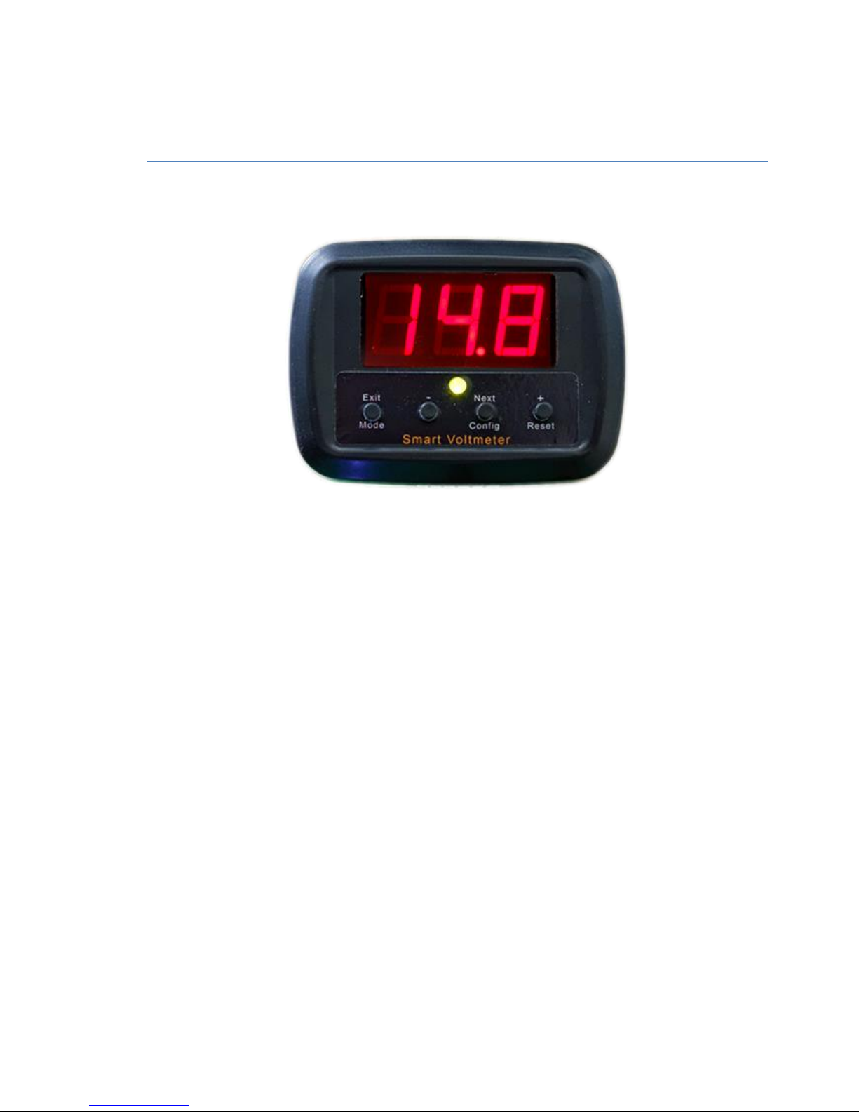
Spl-Lab Smart Voltmeter - is multifunctional digital car voltmeter. Although most of car
electronics manufacturers state that their products have inbuilt protection from supply voltage
sags or swells, in actual practice it turns out that not every, even expensive, amplifier is able to
cope with this task. It means that another voltage overrun can end with expensive repairs or
buying new unit. But if you add to your system an inexpensive device from Spl-Lab you can
forget about such problems once for all. Main functions of the Smart Voltmeter are the
following: measuring exact characteristics of a car electric network voltage, analysing voltage
sags and swells that appear in car electronics operation process, protection of electrical
equipment of a car from breakage, possibility of flexible setting and easy use. The voltmeter can
easily change data refresh speed onscreen (from once a second to once per quarter second),
which allows excluding the unnecessary details or to make measurements with maximum
possible accuracy. The device has three working modes that are changed with just one button:
voltmeter mode; voltmeter mode with sag and swell indication; voltmeter mode with sag and
swell indication and protection feature. For indicating current mode there is a three-coloured
LED. User can easily set permissible voltage range for setting the electrical equipment. In the
Page 4

4
with sag and swell indication mode the car voltmeter displays current voltage and in case if the
permitted range is overstepped, the voltmeter will inform the user about it by holding maximum
or minimum value onscreen for evaluating the degree of sag or swell. In the protection mode in
case if the permitted range is overstepped, the voltmeter will break the remote controlling circuit
before user’s interference, protecting electrical equipment from breakage in doing so. It stands to
mention that Smart Voltmeter is able to commutate the Remote controlling circuit with current
up to 3 ampere, thus in case of necessity replacing an additional relay.Smart Monitor form SplLab will protect your car audio components from breakage, will help in tuning sound in the car,
as well as will measure power of your sound system and acoustics characteristics. Actually the
Smart Monitor replaces amp clamp, True RMS digital voltmeter, and oscilloscope, and in
addition to this provides protecting functions.
Ergonomics
Spl-Lab car voltmeter has compact case, including a three-segment display, 4 control buttons,
three-coloured LED for indicating active working mode and a slot for five contacts that has
several variants of connection to the electric system of the car. The design of the device allows
including it practically in any car interior.
Page 5

5
Technical features
Measured value of direct
current voltage
from 0 to 18 Volt
Measurement accuracy
0.1 Volt
Data refresh speed
one second, half second, quarter
second
Commutated current of
the Remote circuit
3 ampere
Algorithm of measuring
direct voltage
Averaging by time
Display
Three-segment
Sockets/connectors:
five-contact slot
Supply voltage
from 6 to 18 Volt
Dimensions: (LBH)
69x50x21mm
Page 6

6
Working with the device
Important safety information:
! The protection features of the device are intended solely for providing information and do not
exempt from using safety fuses and other classical protection elements.
! The manufacturer does not bear responsibility for damage, caused directly or indirectly, as a
result of improper device use.
! Before using the device, examine its case for cracks and splits, because any depressurization
of the device will result in its breakage.
! To avoid the risk of electric shock all the connector cables should not have insulation defects.
! Avoid measuring load beyond the maximum limit.
! All operations of connecting and disconnecting cables should be performed with equipment
switched off.
! Do not use or store the device in the areas with high humidity or heat, as well as, close to the
devices, generating strong magnetic field.
! During the preventive maintenance of the device do not use the synthetic detergents, do not
apply solvents. Using wet wipes is more preferable.
! Before starting the device and a system on the whole, ensure that all the connection cables are
switched correctly.
Page 7
7
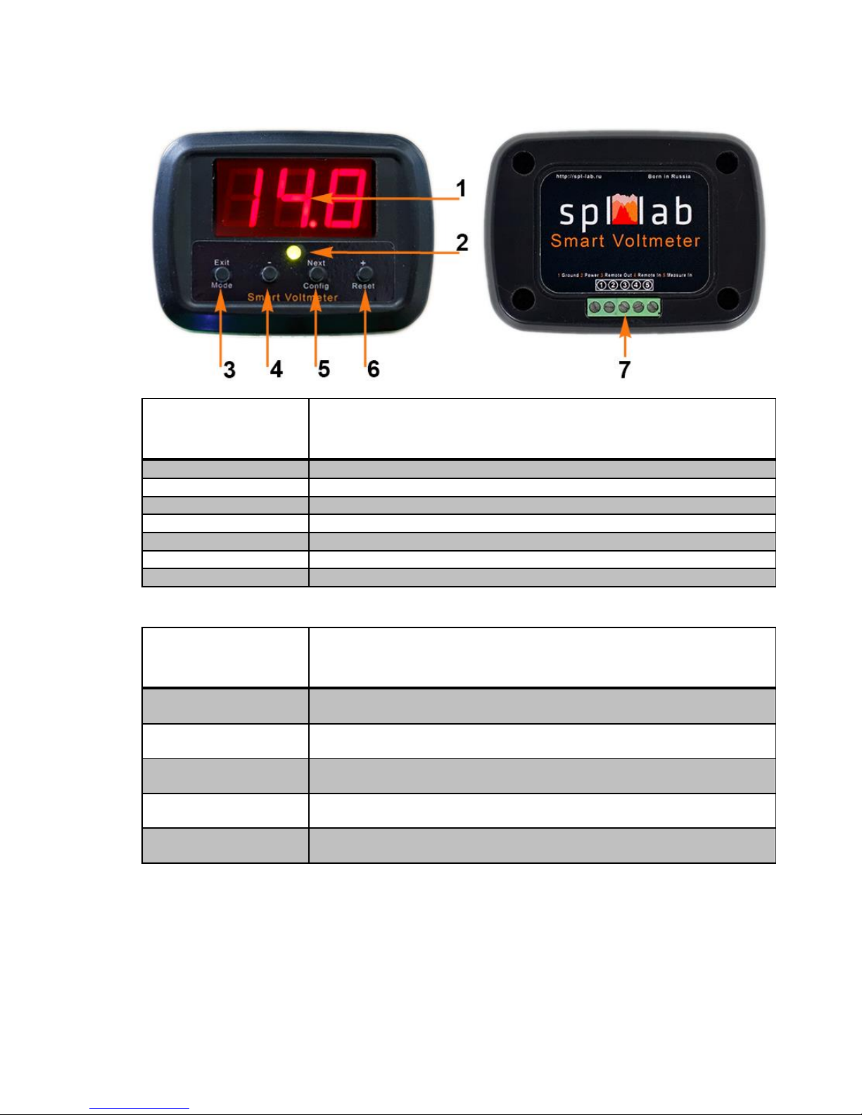
Identifying the functional parts of the device:
Number of the
element
Description
1
Display
2
Work mode indicator
3
Functional button #1
4
Functional button #2
5
Functional button #3
6
Functional button #4
7
The five-contact slot (contact numeration goes from left to right)
Functional purpose of slot contacts
Number of the
element
Description
1
Negative (common), should be connected to the negative contact of the car
electric network.
2
+ 12 V for feeding the device, it is possible to connect to any supply line, for
example to the ignition or to the Remote.
3
Output signal of the Remote controlling circuit should be connected to the
amplifier or other controllable equipment.
4
Input signal of the Remote controlling circuit should be usually connected to
the head unit.
5
Positive of the measured voltage should be connected to the amplifier feed
point or other controllable equipment.
Page 8
8
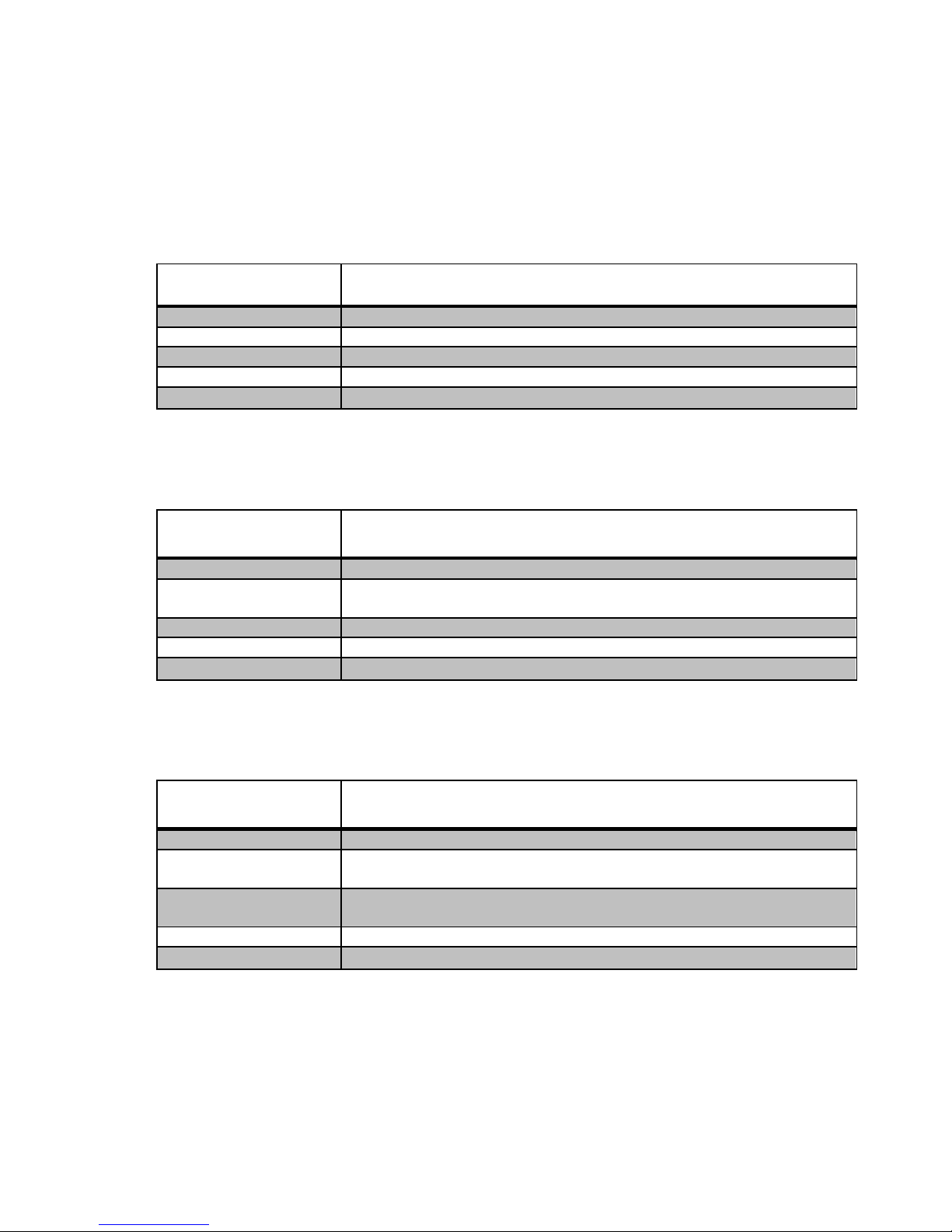
Typical device connection schemes
Simple voltmeter
Such scheme implies that the device works as a simple voltmeter. The two-contact connection
provides device power supply directly from the measured line. Measures voltage range in this
case is limited from 6 to 18 volts.
Contact
Description
1
Should be connected to the negative contact of the car electric network.
2
Should be connected to the measured network spot.
3
Not connected
4
Not connected
5
Connected with contact 2
Disconnectable voltmeter
Such voltmeter connection scheme allows to control switching the device on with or without
measures voltage, thus eliminating a possibility of unnecessary operation.
Contact
Description
1
Should be connected to the negative contact of the car electric network.
2
+ 12 V for feeding the device, it is possible to connect to any supply line, for
example to the ignition or to the Remote.
3
Not connected
4
Not connected
5
Should be connected to the measured network spot.
Voltmeter with protection feature without external control
This voltmeter connection scheme provides the use of external power amplifier protection
feature through Remote circuit. In this case the external control from the head unit is not used.
Contact
Description
1
Should be connected to the negative contact of the car electric network.
2
+ 12 V for feeding the device, it is possible to connect to any supply line, for
example to the ignition or to the Remote.
3
Output signal of the Remote controlling circuit should be connected to the
amplifier or other controllable equipment.
4
Connected with contact 2
5
Should be connected to the measured network spot.
Voltmeter with protection feature with external control
Connection involving all the device features, such as protection, external power supply, and
control. Allows determining the moment when to switch on the device and to use protection
feature for external equipment, such as power amplifiers, applying Remote circuit control for the
head unit.
Page 9
9
Contact
Description
1
Negative (common), should be connected to the negative contact of the car
electric network.
2
+ 12 V for feeding the device, it is possible to connect to any supply line, for
example to the ignition or to the Remote.
3
Output signal of the Remote controlling circuit should be connected to the
amplifier or other controllable equipment.
4
Remote is usually connected to the head unit.
5
Should be connected to the measured network spot.
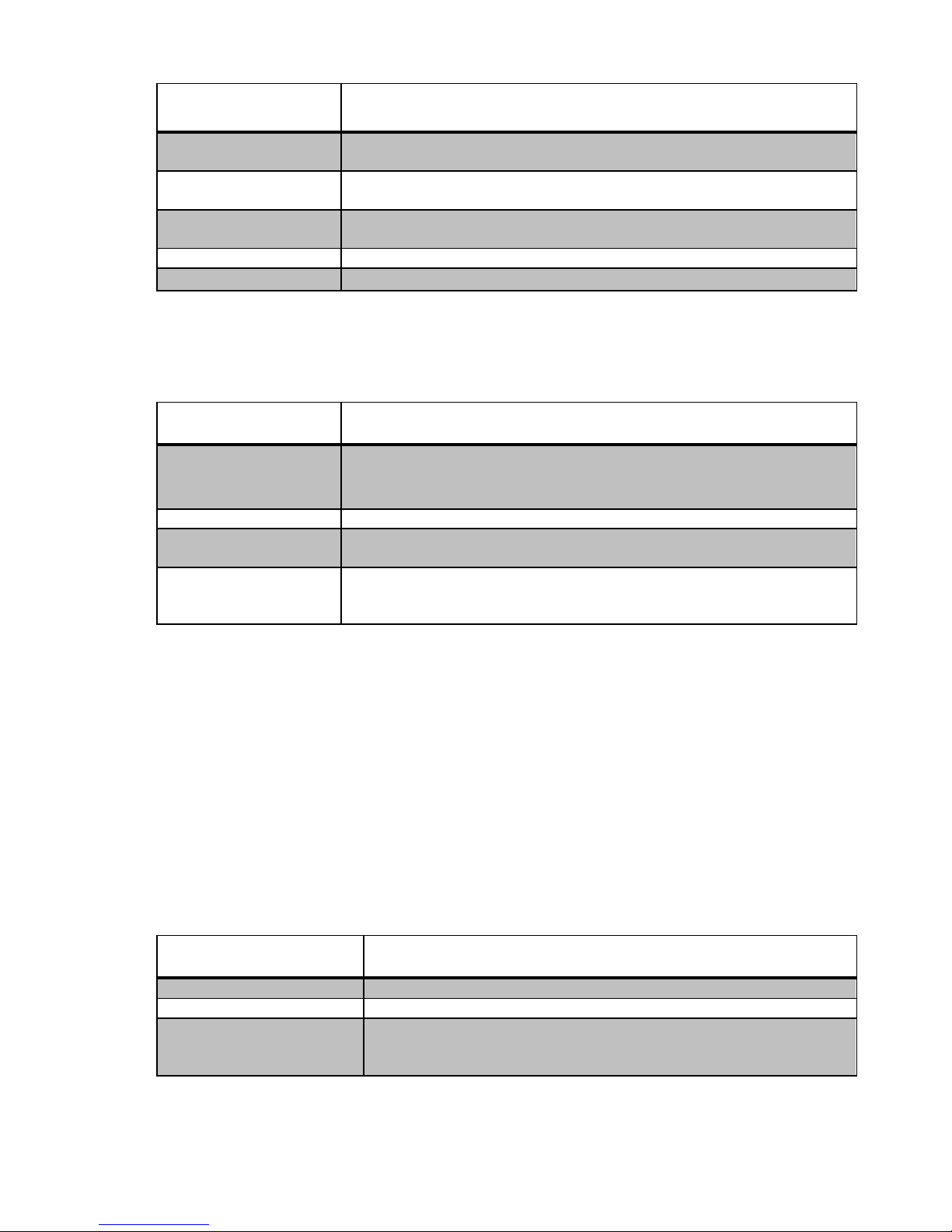
Button assignment
Button
Assignment
Functional button #1
Selecting the work mode or exiting the configuration menu
Functional button #2
Decreasing the selected value in the configuration menu
Functional button #3
Entering the configuration menu or selecting next parameter in the
configuration menu
Functional button #4
Resetting current values and restoring the remote circuit or increasing the
selected value in the configuration menu
Setup mode
For entering the configuration menu press Functional button #3.
Select necessary parameter by pressing Functional button #3.
Set the necessary parameter value using Functional buttons #2 (decreasing value) and #4
(increasing value).
After setting the last parameter and pressing Functional button #3 the device will save
selected parameters and will change to measuring mode.
To exit the configuration menu without saving press Functional button #1
Menu item
Assignment
LO
Setting the lower permissible voltage range value. from 0 to 17.9 Volt
HI
Setting the upper permissible voltage range value. from 0 to 17.9 Volt
SP
Setting data refresh speed onscreen. One dot means that data is refreshed
once a second; two dots - two times a second, and three - four times a
second. Protection actuation speed depends on data refresh speed.
Page 10

10
Device work modes
The Smart Voltmeter has three work modes. Working mode is changed by pressing the
Functional button #1. For indicating current working mode there is a three-coloured LED.
Detailed description of working modes:
Voltmeter (green LED) - the device displays present measured voltage value. The
Remote controlling circuit is closed if the signal on contact #4 (Remote In) of the slot is
present.
Voltmeter mode with sag and swell indication (yellow LED) - the device displays and
checks the value of measured voltage for correspondence with the range set in
configuration menu. If the voltage oversteps the defined range, the device comes into the
pick hold mode changing the value on-screen only in case if value overstepped the
permissible range even more, in so doing the LED and display start blinking until reset
button is pressed. The Remote controlling circuit is closed if the signal on contact #4
(Remote In) of the slot is present.
Voltmeter mode with sag and swell indication and feature of breaking the
controlling circuit (red LED) - the device displays and checks the value of measured
voltage for correspondence with the range set in configuration menu. If the voltage
oversteps the defined range, the device comes into the pick hold mode changing the value
on-screen only in case if value overstepped the permissible range even more, in so doing
the Remote controlling circuit is broken, the LED, and display start blinking until reset
button is pressed. The Remote controlling circuit is closed if the signal on contact #4
(Remote In) of the slot is present.
 Loading...