


Patents Pending
Kinetic Log Splitter
Owners Manual
Model #45-0503
IMPORTANT: The engine is shipped without
oil. Add oil before starting the engine.
Place Model Number Label in Center of this Box.
Before operating your Split Second
Log Splitter, read and understand
WARNING
http://www.splitsecondlogsplitter.com Form No. 41595
all instructions inside this manual.
French and Spanish language manuals
are available to download at
www.splitsecondlogsplitter.com

Table of Contents
Safety and Operational Labels ................................................................3
Safety Rules ..................................................................................4
General Safety ...................................................................................... 4
Engine Safety ....................................................................................... 4
Towing Safety....................................................................................... 4
Hardware Package Contents ..................................................................5
Assembly Instructions ........................................................................5
Assemble the Tow Bar ............................................................................... 5
Assemble the Tray................................................................................... 5
Position the Tow Bar ................................................................................ 5
Install the Bail Pin ................................................................................... 5
Assembly Instructions ........................................................................5
Assemble the Tow Bar ............................................................................... 5
Assemble the Tray................................................................................... 5
Position the Tow Bar and ............................................................................ 5
Operating Instructions........................................................................ 6
Before Using First Time ..............................................................................6
Before Each Use .....................................................................................6
Adjusting the Log Splitter Height ....................................................................6
Towing the Log Splitter .............................................................................. 6
Starting the Engine.................................................................................. 6
Using the Log Splitter ...............................................................................7
Maintenance Instructions .....................................................................9
Check For Loose Fasteners ...........................................................................9
Check Tire Pressure..................................................................................9
Grease the Rack .....................................................................................9
Grease the Flywheel Bearings ........................................................................ 9
Grease the Wheel Bearings .........................................................................10
Engine Maintenance ...............................................................................10
Cleaning...........................................................................................10
Storing ............................................................................................10
Service and Adjustments ....................................................................11
Adjusting the Belt Tension . . . . . . . . . . . . . . . . . . . . . . . . . . . . . . . . . . . . . . . . . . . . . . . . . . . . . . . . . . . . . . . . . . . . . . . . . . 11
Replacing the Belts .................................................................................11
Replacing the Centrifugal Clutch ...................................................................11
Replacing the Wheel Bearings.......................................................................12
Troubleshooting.............................................................................13
Specications ...............................................................................14
Accessories for the Log Splitter...............................................................15
Repair Parts ..............................................................................16-19
Parts Ordering ...................................................................... Back Page
Page 2
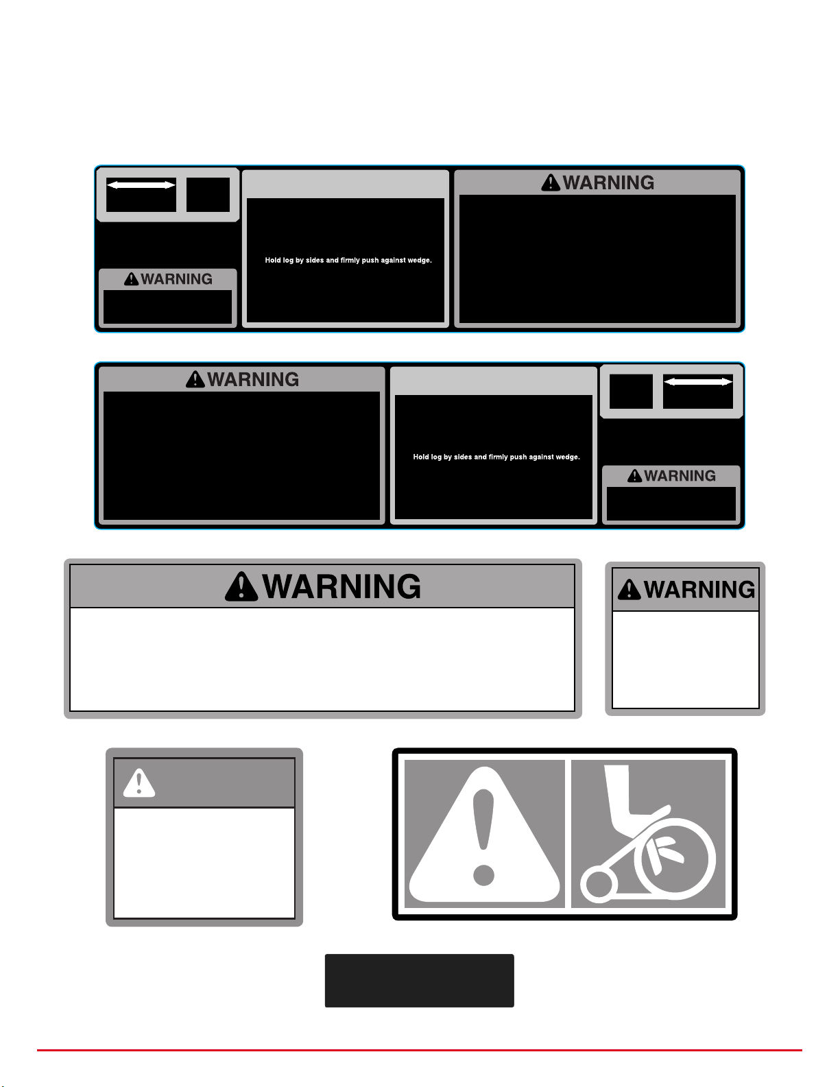
Safety and Operational Labels
This page contains copies of all the Safety and Informational labels that are found on your log splitter. Replace
any damaged or missing labels immediately. Order by the part number shown with each label. Refer to the back
cover for ordering information.
SAFETY
ONOFF
41597
LOADING AND OPERATING THE
MACHINE SHOULD ONLY BE DONE
BY THE SAME PERSON.
• Read owner's manual for safety and operating instructions.
• Read engine owner's manual for safety and operating instructions.
• Never grab log by cut ends when placing on beam against wedge.
• Always split wood in the direction of the grain.
• Always operate log splitter on level ground.
• Always operate log splitter in a well-ventilated area.
• Always secure wheels before operating log splitter.
• Keep hands, body parts, and clothing away from splitting wedge, ram, all
moving parts, and partially split wood.
• Before removing pieces of wood stuck on wedge or in ram area, shut off engine
and wait until all parts have stopped moving.
• Do not operate log splitter without housing and belt guards in place.
• Do not refuel engine while hot or running.
• Keep all bystanders at least 25 feet away during operation.
LOCK
Read owner's manual for safety and operating
instructions.
1. Start engine using instructions from engine manual.
2. Advance engine speed to max.
3. The splitting cycle:
4. Ram automatically retracts at end of stroke. To retract
OPERATION
1. Pick up log by sides and place on beam.
2.
3. .drawrof eldnah kcol ytefas hsuP
4. Pull up on control handle and hold until log is split.
5. Release handle at any time and the ram will retract.
the ram before the end of the stroke, release control
handle.
• Read owner's manual for safety and operating instructions.
• Read engine owner's manual for safety and operating instructions.
• Never grab log by cut ends when placing on beam against wedge.
• Always split wood in the direction of the grain.
• Always operate log splitter on level ground.
• Always operate log splitter in a well-ventilated area.
• Always secure wheels before operating log splitter.
• Keep hands, body parts, and clothing away from splitting wedge, ram, all
moving parts, and partially split wood.
• Before removing pieces of wood stuck on wedge or in ram area, shut off engine
and wait until all parts have stopped moving.
• Do not operate log splitter without housing and belt guards in place.
• Do not refuel engine while hot or running.
• Keep all bystanders at least 25 feet away during operation.
41597
OPERATION
Read owner's manual for safety and operating
instructions.
1. Start engine using instructions from engine manual.
2. Advance engine speed to max.
3. The splitting cycle:
1. Pick up log by sides and place on beam.
2.
3. .drawrof eldnah kcol ytefas hsuP
4. Pull up on control handle and hold until log is split.
5. Release handle at any time and the ram will retract.
4. Ram automatically retracts at end of stroke. To retract
the ram before the end of the stroke, release control
handle.
41598
41599
SAFETY
LOCK
LOADING AND OPERATING THE
MACHINE SHOULD ONLY BE DONE
BY THE SAME PERSON.
ON OFF
41598
• Do not exceed weight capacity of ball or load limits stamped on coupler.
• Always use safety chains when towing.
• Always check that coupler handle is locked before towing.
• Always use correct ball size that is stamped on coupler.
• Always adjust coupler locking pressure on ball before use.
• Check coupler tightness before and after towing 50 miles.
• Always check coupler and ball for damage before towing. Replace if damaged.
• Avoid sharp turns and steep vertical angles when towing to prevent damage to coupler and its components.
41717
DANGER
KEEP BODY
PARTS AND
CLOTHING AWAY
FROM OPENING
41647
41647
41648
LIFT TO ENGAGE
DO NOT
EXCEED
41599
45 MPH
4159941717
41648
41649
Page 3

Safety Rules
Remember, any power equipment can cause injury if operated
improperly of if the user does not understand how to operate the
WARNING
General Safety
y Read and understand the instructions in the owner's manual before operating the log splitter.
y Never allow anyone who has not read and understood these instructions to operate the log splitter.
y Never allow more than one person at a time to use the log splitter. The same person should both load and
operate the log splitter.
y Never allow children to operate the log splitter.
y Never allow children in the area while the log splitter is running. Stop the engine if a child approaches.
y Never allow bystanders in the area of operation when the log splitter is running.
y Never operate the log splitter without all guards and covers in place.
y Do not modify the safety controls. Make sure they are operating properly before each use.
y Do not make any modications to the log splitter.
y Do not use this log splitter for any purpose other than splitting logs.
y Do not exceed the manufacturer's recommended capacity of the log splitter.
y Always check for loose nuts and bolts before each use and tighten any that are found to be loose.
y Always wear safety glasses or goggles while using the log splitter.
y Never wear loose tting clothing or jewelry while operating the log splitter.
y Wear snug tting gloves while operating the log splitter.
y Never operate the log splitter while barefoot or while wearing sandals. Always wear protective shoes with
non-skid soles while operating the log splitter. Safety toe shoes are recommended.
y Always wear hearing protection when using the log splitter for prolonged periods of time.
y Only operate the log splitter on a at, level surface with secure footing.
y Always shut o the engine and make sure all moving parts have come to a stop before making adjustments.
equipment. Exercise caution at all times when using power equipment.
Engine Safety
y Always keep hands away from the engine, belts and pulleys when the engine is running.
y Never run engine in an enclosed area. Adequate ventilation is required to prevent carbon monoxide
poisoning.
y Do not ll the fuel tank indoors, or while the engine is running or while the engine is hot. Reinstall the fuel
tank cap and wipe o any spilled fuel before starting the engine.
y Do not store the log splitter near an open ame or a heat source when fuel is left in the tank.
y Do not operate engine with air cleaner or cover removed. Removal of these parts could create a re hazard.
y Never change the engine governor settings.
y Always allow the engine to cool completely before making adjustments or repairs or cleaning.
y Always disconnect the spark plug wire before making adjustments or repairs. Keep the wire away from the
plug to prevent accidental starting.
y Always allow the engine to cool completely before covering or storing in an enclosed area.
Towing Safety
y Do not exceed the 45 mph while towing the log splitter.
y Always use safety chains when towing.
y Always check that coupler handle is locked before towing.
y Always use correct ball size that is stamped on coupler.
y Check coupler tightness before towing and after towing 50 miles. Adjust locking pressure as required.
y Always check coupler and ball for damage before towing. Replace if damaged.
Page 4
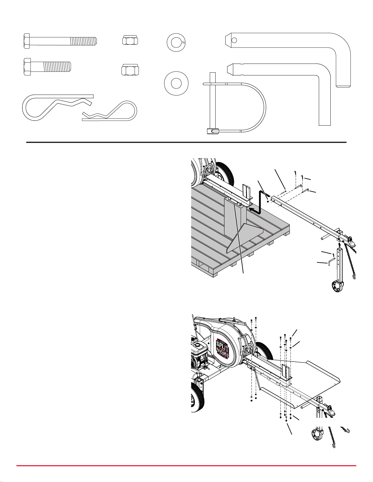
Hardware Package Contents
HAIR COTTER PIN
5/16” x 2-1/2” Hex Bolt
44292 (1 pc.)
3/8” x 1-1/2” Hex Bolt
43062 (6 pcs.)
Hairpin Cotter
714-0117 (2 pcs.)
Hairpin Cotter
43343 (1 pc.)
5/16” Hex Nut
47810 (1 pc.)
3/8” Hex Nut
HA21362 (6 pcs.)
3/8” Lock Washer
43003 (6 pcs.)
3/8” Washer
43081 (6 pcs.)
Assembly Instructions
Assemble the Tow Bar – (See Figure 1.)
1. Remove the front strapping from the log splitter,
but leave the log splitter on the pallet.
2. Insert the front stand into the tow bar and install
the pin through the second hole in the front stand.
3. Slide the tow bar into the receiver tube. Install the
pins through the rst set of holes in the tow bar.
4. Install a 5/16" x 2-1/2" hex bolt and 5/16" nut in the
end hole of the tow bar as a safety catch.
5. Remove the log splitter from the pallet.
Locking Pin
48978 (2 pcs.)
Locating Pin
HA5236 (1 pc.)
48515
Bail Pin
5/16” x 2-1/2” HEX BOLT
5/16” NUT
LOCKING PIN
HAIR COTTER PIN
LOCATING PIN
Assemble the Tray – (See Figure 2.)
1. Slide the tongue in about half way for clearance.
2. From the front of the log splitter, slide the tray onto
the bottom ange of the I-beam. Align the holes in
the tray and the I-beam and install six 3/8" x 1-1/2"
hex bolts and at washers down into the holes.
Assemble 3/8" lock washers and 3/8" nuts onto the
bolts and secure the tray to the I-beam.
Position the Tow Bar
1. Pull the tow bar out to the towing position, or push
it in to the working position. Align the holes in the
tow bar and the receiver tube and install the two
locking pins and hair cotter pins.
Install the Bail Pin
1. Install the bail pin in the trailer hitch coupler.
RECEIVER TUBE
FIGURE 1
3/8” x 1-1/2” HEX BOLT
3/8” FLAT WASHER
3/8” LOCK WASHER
3/8” NUT
FIGURE 2
Page 5
Operating Instructions
FUEL SHUT-OFF VALVE
SPEED CONTROL LEVER
STOP SWITCH
TABLE HEIGHT SETTINGS
Never allow more than one person at a time to use the log splitter. This log splitter is designed for
use by only one person. The same person should both load and operate the log splitter. Use by
WARNING
Before Using First Time
1. Place the log splitter on level ground and add oil as instructed in the engine owner's manual.
Before Each Use
1. Check the oil level with the log splitter on at, level ground. Add oil as instructed in the engine manual.
2. Check the tire pressure. Fill to the recommended pressure that is stamped on the side of the tires.
3. Check for loose fasteners. Tighten any fasteners that are loose.
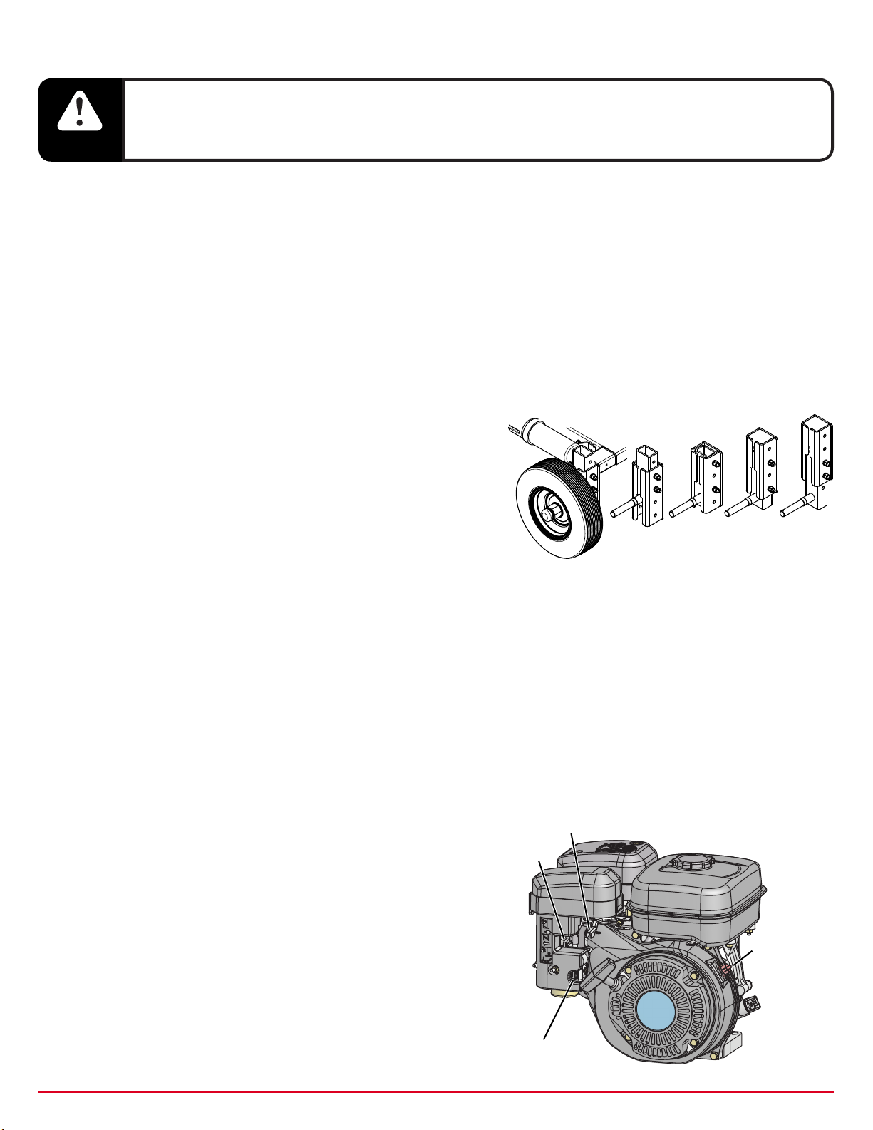
Adjusting the Log Splitter Height – (See Figure 3.)
1. Use a jack to lift the rear of the log splitter. Place supports
under the frame for stability.
2. Remove the bolts from the leg assemblies and move the
wheels to one of four height settings.
3. Reinstall the bolts and nuts and tighten securely.
4. Repeat for the other wheel.
5. Remove the supports from under the rear of the splitter
frame and lower it using the jack.
6. Adjust the front leg stand so that the front of the splitter is
the same height as the rear of the splitter. For the lowest
setting, extend the tow bar out to the towing position.
more than one person at a time creates a risk of injury.
26.5"
29.0"
31.5"
FIGURE 3
34.0"
Towing the Log Splitter
1. Be sure that you are in compliance with all applicable towing laws and regulations.
2. Adjust the height of the log splitter to approximately match the height of the towing vehicle's hitch.
3. Attach the log splitter to a 2" ball hitch on the towing vehicle.
4. Remove the front leg stand if there is not enough ground clearance in the raised position.
5. Adjust the coupler locking pressure and lock the coupler handle.
6. Attach the log splitter's safety chains to the towing vehicle.
7. Raise the plastic rod at the rear of the splitter, leaving 4" or 5" extended below the rod holder.
8. Do not exceed 45 mph while towing the log splitter.
9. Avoid sharp turns and steep vertical angles when towing the log splitter.
Starting the Engine – (See Figure 4.)
1. Set the Fuel Valve Lever to the "I" (OPEN) position.
2. Turn the Stop Switch to the "I" (ON) position.
3. Set the Speed Control Lever to 1/3 of full speed.
4. Close the Choke Lever by moving it to the left if the
engine is cold or the air temperature is low. If the
engine is warm or the air temperature is high, close
the Choke Lever only halfway or leave it fully open.
5. Pull the starter rope slowly until resistance is felt, then
return the rope to its starting position. Pull swiftly on
the handle to start the engine.
6. After the engine is running, gradually move the
Choke Lever to the right until it is fully opened.
Page 6
CHOKE LEVER
FIGURE 4

WARNING
Never allow more than one person at a time to use the log splitter. This log splitter is designed for
use by only one person. The same person should both load and operate the log splitter. Use by
more than one person at a time creates a risk of injury.
Using the Log Splitter
Always stand in the operator zone when
operating the log splitter. Keep your body and
WARNING
1. Select logs for splitting that are cut square on the ends and
are no more than 24" long.
2. Place the log splitter on at, level ground that provides
secure footing.
3. Secure the wheels to prevent unexpected movement.
4. Start the engine and set the throttle to "Fast".
5. Grasp a log on the sides and place it on the log splitter,
centering it on the I-beam. Push the log rmly against the
wedge to help hold it in place. (See Figure 6.)
WARNING
hands away from the ram and the wedge while
the ram is in motion. (See gure 5.)
Do not grasp the log by the ends when loading it
onto the log splitter. (See gure 7.) Doing so may
lead to a potentially severe injury. Always grasp
logs on the sides when loading.
OPERATOR
ZONE
OPERATOR
ZONE
FIGURE 5
FIGURE 6
6. If one end of a log is not cut square, position the log so that
the slanted end faces toward the wedge and butts against the
bottom of the wedge. (See gure 8.)
FIGURE 7
FIGURE 8
Page 7

Never attempt to split logs across the grain;
damage to the splitter or injury to you could
WARNING
occur. (See Figure 9.) Always split logs end to end,
with the grain.
7. If a log is forked, split one leg at a time. Do not try to split down
the middle of the fork. (See Figure 10.)
8. To activate the ram, place one hand on the lock out lever and
the other hand on the engagement handle. Pull forward on
the lock out lever and then lift up rmly on the engagement
handle. Continue lifting up on the handle until the log is fully
split or until the ram reaches the end of its stroke, then release
the handle to retract the ram. (See Figure 11.)
NOTE: To retract the ram at any time during the forward stroke,
simply release the engagement handle.
Keep hands away
from the log while
WARNING
the ram is in motion.
FIGURE 9
FIGURE 10
9. If the ram stops before the log is completely split, release the
handle immediately and allow the ram to fully retract. Repeat
the splitting cycle until the log is split.
NOTE: Do not allow the gear teeth to grind if the ram stops before
the log is split. Release the engagement handle immediately
to avoid excessive wear or damage to the gear teeth.
10. If the ram becomes stuck in the log and will not retract,
immediately strike downward on the engagement handle to
disengage the gear teeth and retract the ram.
11. If a log becomes stuck on the wedge, shut o the engine and
wait 30 seconds, or until the ywheels stop rotating, before
removing the log. Dislodge the log by pulling it straight back,
working it straight up and down as necessary, to remove it from
the wedge. Do not push the log side to side to remove it.
Never try to dislodge a stuck log while the
engine is running. First shut o the engine and
WARNING
wait 30 seconds, or until the ywheels have
stopped rotating.
ENGAGEMENT
HANDLE
LOCK-OUT
LEVER
FIGURE 11
12. Remove logs from the work table as they are split.
13. Keep the beam dry and scraped clean of build-up during use, to allow the ram to slide freely.
Page 8

Maintenance Instructions
PROCEDURE BEFORE EACH
USE
Check for loose fasteners
Check tire pressure
Check engine oil level
Change engine oil
Check and clean air cleaner
Grease Rack
Grease ywheel bearings
Clean spark arrester
Clean spark plug
Grease wheel bearings
Replace air cleaner
1 - After 20 hours of operation for the rst oil change only.
ü
ü
ü
AFTER 20
HOURS
1
ü
EVERY 50
HOURS
ü
ü
Check For Loose Fasteners
1. Do a visual check and tighten any fasteners which may have worked loose during use.
EVERY 100
HOURS
ü
ü
ü
ü
(once a year)
(every 200 hours)
Check Tire Pressure
1. Check tire pressure before each use, and before towing the splitter on the highway. Fill to the
recommended pressure that is stamped on the tire sidewall.
Grease the Rack
1. Wipe a light coat of all purpose grease onto the teeth on the bottom of the rack after every 50 hours of
operation or every 5 cords split.
Grease the Flywheel Bearings
1. Lubricate the ywheel bearings every 100 hours. Pump a small amount of No. 2 or 3 lithium base grease
into the grease ttings. Wipe o excess grease from bearings. Clean o any grease that falls onto the top
surface of the I-beam between the bearings.
Page 9

Grease the Wheel Bearings – (See Figure 10.)
HUB CAP
COTTER PIN
1. Use a jack to lift the rear of the log splitter. Place supports
under the frame for stability.
2. Remove the hub cap and pull the cotter pin from one axle.
3. Unscrew the slotted nut and remove the washer, the loose
ROLLER BEARING
SEAL
WASHER
roller bearing and the wheel from the axle.
4. Remove the seal and the bearing from the other end of
the wheel hub by carefully tapping on the back side of the
bearing in a circular pattern.
5. Wipe o old grease from the bearings and the inside of
the wheel hub. Clean the bearings and wheel hub with
kerosene or solvent, then spray with brake cleaner. Allow
parts to dry before proceeding.
6. Inspect the bearings and seal for damage. Replace worn or
damaged parts.
ROLLER BEARING
WASHER
SLOTTED NUT
7. Apply a generous amount of high quality wheel bearing
grease to the roller bearings, working it around the rollers
FIGURE 12
and into the bearing until the rollers are coated and the
bearing cage is lled.
8. Apply high quality bearing grease to the bearing races that are pressed into the wheel hub.
9. Assemble a bearing into the inward facing end of the wheel hub, and then carefully tap a seal into the end
of the hub.
10. Slide the wheel onto the axle and then install another bearing and a washer into the wheel hub.
11. Thread the slotted nut onto the axle and tighten rmly while spinning the wheel to seat the bearings. Back
the nut o until a slot aligns with the hole in the spindle. Make sure that the wheel spins freely but does
not have end play or wobble. Readjust the nut as necessary.
12. Install the cotter pin and spread the ends.
13. Install the hub cap.
14. Repeat the same procedure for the other wheel.
15. Remove the supports from under the rear of the splitter frame and lower it using the jack.
Engine Maintenance
NOTE: Refer to the instructions in the engine manual for performing the following procedures.
1. Check oil level before each use. Be sure the log splitter is resting on at, level ground.
2. Change the oil after the rst 20 hours of operation and then after every 100 hours of operation.
3. Service air cleaner every 50 hours under normal conditions. Clean every few hours under extremely dusty
conditions. Poor engine performance and ooding usually indicate a dirty air cleaner.
4. The spark plug should be cleaned and the gap checked every 100 hours.
5. Clean the spark arrester every 100 hours.
Cleaning
1. Clean the engine regularly with a cloth or brush. Keep the cooling ns on the engine housing clean to
allow proper cooling. Remove all dirt and debris from muer area.
2. Clean the I-beam, scraping any compacted residue o the top surface.
Storing
1. Clean the log splitter before storing.
2. Store in a dry protected area or cover with a water-resistant cover (optional 45-0509 Cover available).
Page 10

Service and Adjustments
FIGURE 15
Adjusting the Belt Tension – (See Figure 11 and 12.)
NOTE: The belt tension is correct when moderate pressure,
applied to the belts midway between the two pulleys,
results in 1/2" of deection of the belts.
1. Loosen the nuts on the four round head carriage bolts that
secure the motor slide plate to the frame assembly.
2. To increase the belt tension, adjust the two nuts on the end
of the tensioning bolt, loosening the outer nut and then
tightening the inner nut until 1/2" of belt slack is attained.
Tighten the outer nut.
3. To decrease the belt tension, adjust the two nuts on the end
of the tensioning bolt, loosening the inner nut until 1/2" of
belt slack is attained. Tighten the outer nut.
Replacing the Belts – (See Figure 11 and 12.)
1. Remove the plastic housing from the log splitter, starting
with the left side. (The side away from the engine.)
2. Remove the belt guard from the log splitter.
3. Loosen the nuts on the four round head carriage bolts that
secure the motor slide plate to the frame assembly.
4. Loosen the two nuts on the end of the tension adjusting
bolt and screw the inner nut as far as possible onto the bolt.
5. Slide the engine forward and remove the belts.
6. Install new belts and adjust the belt tension using the
instructions in the "Adjusting the Belt Tension" section.
7. Replace the belt guard.
8. Replace the plastic housing. (It is easiest to replace the right
side housing rst.)
TENSIONING BOLT
APPR. 1/2"
INNER
NUT
OUTER
NUT
FIGURE 13
Replacing the Centrifugal Clutch – (See Figure 13.)
1. Remove the belt guard from the log splitter.
2. Remove the bolt and washer from the engine shaft.
3. Remove the clutch and the square key from the engine shaft.
4. Install a new centrifugal clutch and the square key that you
removed onto the engine shaft.
5. Secure the clutch to the engine shaft with the bolt and
washer that were removed.
6. Reattach the belt guard.
FIGURE 14
SQUARE KEY
CLUTCH ASSEMBLY
FLAT WASHER
SELF LOCKING
HEX BOLT
Page 11

Replacing the Wheel Bearings – (See Figure 14.)
HUB CAP
COTTER PIN
1. Use a jack to lift the rear of the log splitter. Place supports
under the frame for stability.
2. Remove the hub cap and pull the cotter pin from one axle.
3. Unscrew the slotted nut and remove the washer, the loose
ROLLER BEARING
SEAL
WASHER
roller bearing and the wheel from the axle.
4. Remove the seal and the bearing from the other end of
the wheel hub by carefully tapping on the back side of the
bearing in a circular pattern.
5. Discard the roller bearings and the seal.
6. Wipe o old grease from the inside of the wheel hub and
then wash out with kerosene or solvent. Finish by spraying
with brake cleaner. Allow to dry thoroughly.
7. Apply high quality wheel bearing grease to the bearing
races that are pressed into the wheel hub.
ROLLER BEARING
WASHER
SLOTTED NUT
8. Apply a generous amount of high quality wheel bearing
grease to the new roller bearings, working it around the
FIGURE 16
rollers and into the bearing until it the rollers are coated
and the bearing cage is lled with grease.
9. Assemble a new bearing into the inward facing end of the wheel hub, and then carefully tap a new seal
into the end of the hub.
10. Slide the wheel onto the axle and then install another new bearing and a washer into the wheel hub.
11. Thread the slotted nut onto the axle and tighten rmly while spinning the wheel to seat the bearings. Back
the nut o until a slot aligns with the hole in the spindle. Make sure that the wheel spins freely but does
not have end play or wobble. Readjust the nut if necessary.
12. Install the cotter pin and spread the ends.
13. Install the hub cap.
14. Repeat the same procedure for the other wheel.
15. Remove the supports from under the rear of the splitter frame and lower it using the jack.
Page 12

Troubleshooting
PROBLEM POSSIBLE CAUSE(S) CORRECTIVE ACTION
Engine fails to
start
Engine overheats 1. Engine oil level low.
Loss of power;
operation erratic
Rack won't
retract
completely
1. Stop switch at OFF position
2. Fuel shut-o valve closed.
3. Fuel tank empty, or stale fuel.
3. Spark plug wire disconnected.
5. Faulty spark plug.
2. Carburetor not adjusted properly.
1. Spark plug wire loose
2. Unit running on CHOKE.
3. Blocked fuel line or stale fuel.
4. Water or dirt in fuel system.
5. Carburetor out of adjustment.
6. Dirty air cleaner.
7. Loose or worn belts.
8. Worn clutch.
1. Dirty beam
2. Machine not level - wedge end too
low.
3. Worn return springs.
4. Broken return springs.
5. Worn or damaged rack support
bearing.
1. Turn switch to ON.
2. Open fuel shut-o valve.
3. Fill tank with clean, fresh fuel.
4. Connect wire to spark plug.
5. Clean, adjust gap or replace.
1. Fill crankcase with proper oil.
2. Adjust carburetor.*
1. Connect and tighten spark plug wire.
2. Move choke lever to OFF position.
3. Clean fuel line; ll tank with clean fresh
gasoline.
4. Disconnect fuel line at carburetor to drain fuel
tank. Reconnect fuel line and rell with fresh fuel.
5. Adjust carburetor.*
6. Service air cleaner.*
7. Adjust belt tension or replace belts.
8. Replace clutch.
1. Scrape o top of beam, then wipe o loose dirt.
2. Place on more level ground.
3. Hook ends of springs on next notch.
4. Replace springs.
5. Replace bearing.
Gear teeth won't
stay engaged
* -Refer to the engine manual packed with your unit.
1. Engagement engagement handle
has not been pulled up quickly enough
or with enough force.
2. Rack gear bent from overloading.
1. Pull up on the handle more quickly and with
more force.
2. Replace the rack gear.
Page 13

Specications
Wheels/Tires Highway rated at 45 MPH
Hitch Type 2" Ball Hitch
Towbar Retractable
Max Log Diameter 30 in
Max Log Length 24 in
Cycle Time 3 seconds
Rack Width 2.25 in.
Pinion Shaft Diameter 1.5 in.
Ram Carriage 4 Heavy Duty Sealed Bearings
Flywheel Diameter 18.25 in.
Flywheel Weight 2 at 90 lbs. each
Flywheel Max RPM 365
Splitter Beam Height Adjustable Range 26.5 in. to 34 in.
Splitter Length 112 in.
Splitter Width 55.0 in.
Table Dimensions 33.0 in. x 40.0 in. long
Wedge Height 7.0 in
Wedge Length 5.0 in.
Wedge Thickness 0.75 in.
Weight 570 lbs.
Engine Subaru SP170
Starting Type Recoil
Engine Displacement 169 cc
Horsepower 6 HP
Page 14

Accessories for the Log Splitter
45-02312 FIRE WOOD CART
45-0506 LOG DOLLY
45-0507 LOG LIFT ATTACHMENT
45-0505 TOOL TRAY
45-0509 COVER
Not Shown
Page 15

45-0503 Repair Parts Illustration
the fastest way to purchase parts
www.speedepart.com
63
39
64
63
23
36
2
29
10
31
35
54
4
32
28
6
29 66
30
31
7
34
66
53
30
36
3
24
26
57
36
5
33
38
25
31
52
37
65
45
8
36
9
13
12
13
40
27
33
30
35
55
31
14
13
56
13
15
1
38
52
40
37
41
44
21
60
60
59
52
37
22
61
48
20
58
38
52
19
15
13
Page 16
13
14
42
45
13
12
13
31
11
29
30
43
11
44
47
16
17
51
50
18
49
48
62
44
46

45-0503 Repair Parts List
the fastest way to purchase parts
www.speedepart.com
REF QTY PART
NO
1
2
3
4
5
6
7
8
9
10
11
12
13
14
15
16
17
18
19
20
21
22
23
24
25
26
27
28
29
30
31
32
33
1 42920 Housing
1 42916 Housing
2 42901 V-Belt
1 42900 Engine
1 42927 Clutch
1 27623 Plate, Motor Slide
1 68234 Bracket, Rear Housing
1 27648 Cover, Clutch
1 67952 Frame Assembly
1 41628 Manual Container
2 68029 Leg Assembly
2 68284 Wheel and Tire Assembly
2 68285 Bearing Kit (includes one seal,
2 43601 Washer, 1.59 x 1.03 x .06
2 41636 Nut, Slotted 1-14 2A
1 42891 Wheel
1 27722 Bracket, Front Wheel
1 68005 Front Stand
1 42935 Safety Chain W/Hooks
1 42928 Trailer Hitch Coupler
1 68024 Tow Bar
1 67953 Work Table
1 42759 End Marker
4 43085 Hex Bolt, 5/16-18 x 1-1/2"
1 47600 Hex Bolt, 5/16-24 Self Lock
1 736-0231 Washer, .344" x 1.125" x .12"
1 41635 Key
4 44326 Carriage Bolt, 5/16-18 x 1"
10 43088 Washer, 5/16"
14 43086 Lock Washer, 5/16"
14 47810 Hex Nut, 5/16" Nylock
1 44071 Hex Bolt, 3/8-16 x 3-1/2"
3 44072 Hex Nut, 3/8-16 Whizlock
DESCRIPTION
one hub cap, two bearings,
and one item #45 cotter pin)
REF QTY PART
NO
34
35
36
37
38
39
40
41
42
43
44
45
46
47
48
49
50
51
52
53
54
55
56
57
58
59
60
61
62
63
64
65
66
1 43661 Hex Bolt, 1/4-20 x 1"
4 47189 Hex Nut, 1/4-20 Nylock
11 43063 Hex Bolt, 5/16-18 x 1"
11 HA21362 Hex Nut, 3/8-16 Nylock
11 43062 Hex Bolt, 3/8-16 x 1-1/2"
1 27828 Bracket, End Marker
10 43003 Lock Washer, 3/8"
1 44292 Hex Bolt, 5/16-18 x 2-1/2"
4 47024 Hex Bolt, 1/2-13 x 4-1/2"
4 43353 Lock Washer, 1/2"
7 41657 Hex Nut, 1/2-13 Nylock
2 43501 Cotter Pin, 9/64" x 1-1/2"
1 27746 Spacer
1 48115 Hex Nut, 1/2-13 Jam Nylock
3 46286 Hex Bolt, 1/2-13 x 3"
1 42980 Washer, Plastic
1 HA5236 Locating Pin, 1/2"
1
12 43081 Washer, 3/8"
4
1 41598 Label, Warning/Operation RH
1 41597 Label, Warning/Operation LH
1 41647 Label, Danger
1 41648 Label, Danger
1 41599 Label, Warning/Towing Safety
1 41717 Label, Warning/Maximum MPH
2 49449 Plug
1 48515 Bail Pin
1 1540-59 Washer, .52" x 1.062" x .09"
2
2
1
6
1 41595 Owners Manual
43343
41633 U-Nut, 5/16-18 Tinnerman
41726
44950
27829
41730
DESCRIPTION
Hairpin Cotter, 3/32"
Grommet, Rubber
Carriage Bolt, 1/4-20 x 3/4"
Cover, Front Clutch
Plastic Washer, Black
Page 17

45-0503 Repair Parts Illustration - Continued
the fastest way to purchase parts
www.speedepart.com
50
68
51
18
33
49
48
48
49
17
47
46
46
67
6
45
48
31
44
38
33
16
15
42
14
5
47
13
46
67
40
39
4
19
6
52
39
53
21
45
57
22
55
56
59
64
28
48
28
62
63
10
46
2
65
29
47
1
69
66
45
27
20
54
58
23
24
60
25
26
61
48
45
12
43
11
41
10
9
70
7
31
38
4
39
40
57
34
35
32
37
3
69
8
36
30
29
47
61
Page 18

45-0503 Repair Parts List - Continued
the fastest way to purchase parts
www.speedepart.com
REF QTY PART NO DESCRIPTION
1 1 67948 I-Beam Assembly
2 1 68232 Upper Housing Bracket
3 1 68233 Lower Housing Bracket
4 2 42922 Bearing
5 1 42864 Spur Shaft
6 2 42800 Flywheel, 90 LB.
7 1 27640 Spindle Shaft
8 1 27703 Lever, Lock Out
9 1 41669 Grip
10 6 42924 Bearing
11 1 67956 Ram Engagement Assembly
12 1 42911 Engagement Rod
13 1 42923 Lock Out Pin
14 1 27702 Bracket, Lock Out
15 1 HA19445 Spring
16 1 27643 Bracket, Pin Support
17 1 42915 Handle Grip
18 1 42914 Engagement Handle
19 1 42863 Rack
20 1 67954 Ram Head Assembly
21 1 42918 Spring, Rack Support
22 1 27645 Plate, Rack Support
23 1 27646 Bracket, Bearing Holder
24 1 42919 Bearing
25 1 67955 Ram Head Slider Assembly
26 1 27639 Plate, Brass Slider
27 2 42917 Spring, Rack Return
28 2 27638 Bracket, Bearing Support
29
30 2 43062 Hex Bolt, 3/8-16 x 1-1/2"
31 2 41646 Bearing, Needle
32 1 43661 Hex Bolt, 1/4-20 x 1"
33 2 47189 Hex Nut, 1/4-20 Nylock
34 2 43069 Carriage Bolt, 3/8-16 x 1-1/2"
35 2 44072 Hex Nut, 3/8-16 Whizlock
4
41730
Plastic Washer, Black
REF QTY PART NO DESCRIPTION
36 2 42925 Bumper Stop
37 2 46978 Hex Nut, 1/4-20 SIMS
38 2 1650-1 Retaining Ring
39 10 43353 Lock Washer, 1/2"
40 8 R74780828 Hex Bolt, 1/2-13 x 1-3/4"
41 1 43082 Hex Lock Nut, 3/8-16 2-Way
42 1 43509 Hex Bolt, 3/8-16 x 2-3/4
43 1 44101 Cotter Pin, 3/32" x 3/4"
44 1 43081 Washer, 3/8"
45 6 47810 Hex Nut, 5/16-18 Nylock
46
47 8 43063 Hex Bolt, 5/16-18 x 1"
48 14 HA21362 Hex Nut, 3/8-16 Nylock
49 2 HA4506 Washer, .406" x 1.5"
50
51 1 1509-69 Hex Bolt, 1/4-20 x 1-3/4"
52 2 41596 Hex Bolt, 1/2-13 x 2"
53 1 42934 Shoulder Bolt, Socket Head
54 1 41657 Hex Nut, 1/2-13 Nylock
55 2 43177 Lock Washer, 1/4"
56 2 43866 Hex Bolt, 1/4-20 x 5/8"
57 2 43088 Washer, 5/16"
58 1 43840 Hex Bolt, 5/16-18 x 1-1/4"
59 1 41634 Skt. Hd. Bolt, 5/16-18 x 1-1/4"
60 6 43574 Hex Bolt, 3/8-16 x 3"
61 8 43003 Lock Washer, 3/8"
62 4 43432 Hex Bolt, 3/8-16 x 2-1/2"
63 4 44137 Washer, .518" x 1" x .02"
64 2 42210 Hex Nut, 3/8-16 Jam Nylock
65 2 714-0117 Hair Cotter Pin, 5/32"
66 2 48978 Pin
67 2 42926 Key, 3/8" Square
68 1 41649 Label, Control Handle
69
70
4 41638 Skt. Hd. Cap Bolt, 3/8-16 x 1"
1 41655 Grip
4 43086 Lock Washer, 5/16"
1
41735
Spacer
Page 19

the fastest way to purchase parts
www.speedepart.com
We truly appreciate your purchase of the Split Second Log Splitter. After you have split a few thousand pieces of
rewood, please take a picture and send us an e-mail. We would enjoy seeing you with your pile of rewood.
Best Regards,
Mike Cohan
President
Agri-Fab, Incorporated
Sullivan, Illinois
REPAIR PARTS
Agri-Fab, Inc.
809 South Hamilton
Sullivan, IL 61951
1-800-448-9282
www.splitsecondlogsplitter.com
Once photos and information are submitted to Agri-Fab, Inc., the submitter is granting Agri-Fab, Inc., permission to use photos,
pictures, or images deemed necessary by Agri-Fab, Inc. Agri-Fab, Inc., cannot and will not be held responsible for any legal
consequences of images submitted by its users.
© 2014 Agri-Fab, Inc.
 Loading...