

Page 1
INSTALLATION AND INSTRUCTION MANUAL
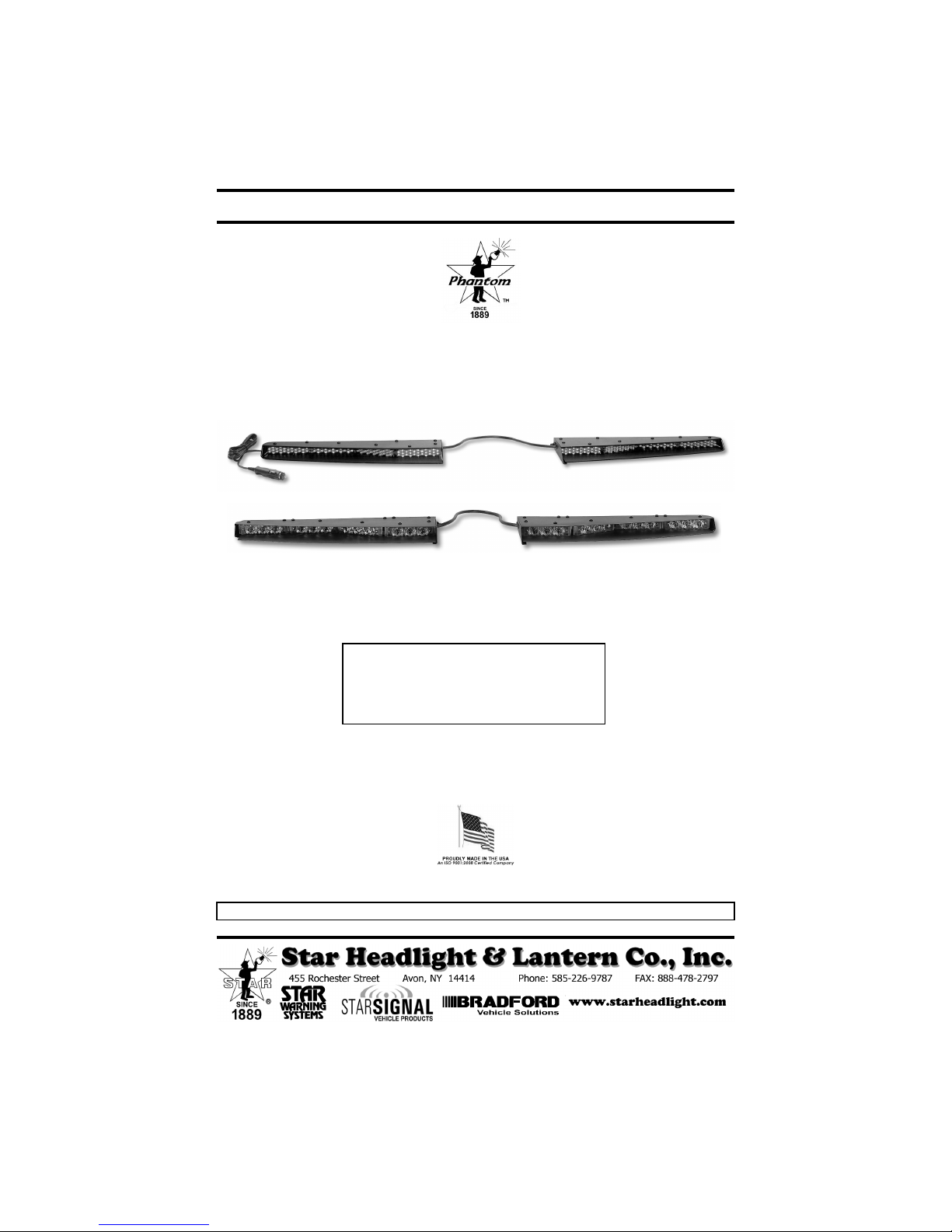
The Split Phantom
The Split Phantom
Undercover Interior LED Lightbar
Models
ULB21 ULB24
(Discrete) (Gen 4 Starburst)
™
IMPORTANT: Please read all of the following instructions before installing your new warning light.
PLIT390 REV. F 10/16/12
Page 2
Due to continuous product improvements, we must reserve the right to change any
NOTICE
specifications and information, contained in this manual at any time without notice. Star
Headlight & Lantern Co., Inc. makes no warranty of any kind with regard to this manual,
including, but not limited to, the implied warranties of merchantability and fitness for a particular
purpose. Star Headlight & Lantern Co., Inc. shall not be liable for errors contained herein or for
incidental or consequential damages in connection with the furnishing, performance, or use of
this manual.
IMPORTANT: Please read all of the following instructions before installing your new
CAUTION: Please be sure to check that your cigarette plug outlet is properly fused. Testing the
WARNING!!!! Care should be taken when positioning this warning light so that the light and/or
Please Note: These instructions are provided as a general guideline only. Specific
mounting and/or wiring, may be necessary and are the sole responsibility of the
installer. Star Headlight & Lantern Co., Inc. assumes no responsibility for the
integrity of the installation for this or any of its products.
light before this fuse is properly installed will void the warranty on the light.
Split Phantom
cord does not interfere with the proper operation of the driver-side or passengerside airbag! Failure to heed this warning may result in serious or fatal injury.
™
LED undercover lightbar.
The Split Phantom
™
uses state-of-the-art Light Emitting Diode (LED)
technology. This warning light is comprised of ultra-high intensity LEDs that
are operated by a micro-controller to efficiently produce light output with
lifetimes up to 100,000 hours.
CAUTION: All of our DC powered warning lights are polarity
sensitive. These lights are polarity protected only if the
appropriate fuse is used. All wires connected to the positive
terminal of the battery should be fused at the battery for their
rated load. Testing the light before this fuse is properly
installed will void the warranty on the light.
-1-
Page 3
Optional Mounting Brackets
There are several optional mounting brackets that can be used to mount your
Split Phantom
the light was ordered.
Please Note: Every ULB21 comes with a standard baffle included. The 274-ULB21-CH
and 274-ULB21-CH11 kits also include a separate baffle that is specifically designed to
fit the Dodge Charger. It should be used in place of the standard baffle included.
™. Your light comes with the one that was selected at the time
274-ULB21-U1 Universal Mounting Kit
274-ULB21-CH 2006-2010 Dodge Charger
2007-2008 Dodge Magnum
2009 Dodge Ram
274-ULB21-CH11 2011 Dodge Charger
274-ULB21-CP 2011 Chevrolet Caprice
274-ULB21-CV 2006-2011 Ford Crown Victoria
2009 Ford F150 and F250
274-ULB21-EX 2006-2010 Ford Explorer
2007-2010 Ford Expedition
274-ULB21-IM 2008-2010 Chevrolet Impala
274-ULB21-INT 2012 Ford Interceptor (Taurus)
274-ULB10-RM 2012 Dodge Ram 1500
274-ULB21-TA 2007-2011 Chevy Tahoe
2007-2011 Chevy Yukon
2007-2011 Chevy Suburban
Star Headlight & Lantern Co., Inc. assumes no
responsibility for the secure mounting of this light. It is the
responsibility of the installer and/or owner to ensure the
lightbar is mounted securely. Check your light every time
you enter the vehicle to ensure that it is mounted securely.
-2-
Page 4
Mounting Instructions
The following mounting instructions describe the standard, most
common way to mount this light. This method may or may not apply to
your vehicle. Because vehicles can vary widely in their design, it may be
necessary to configure the brackets differently than described. Some
applications may require you to design your own custom brackets. The
installer assumes all responsibility for the integrity of the installation. It is
the sole responsibility of the owner to ensure the light is secure.
The
Split Phantom
of your vehicle. It is not intended for exterior applications and is
not warranted against water damage.
It is the sole responsibility of the owner to ensure the warning light is
secure. Check your light every time you enter the vehicle to ensure that
it is mounted securely. The manufacturer assumes no responsibility for
the secure mounting of this light.
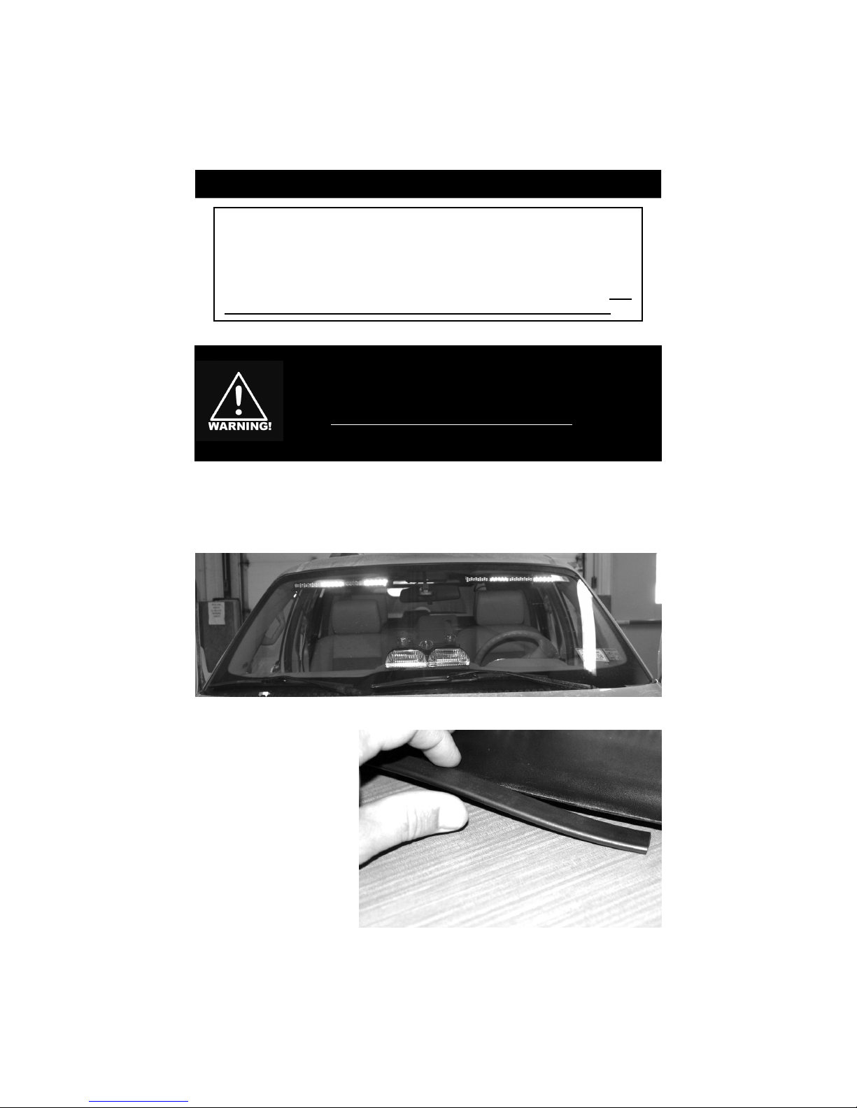
The ULB21 is designed to be mounted in the front windshield of a vehicle using
both of the pre-existing visor clips. An alternate method is also shown using the
Universal Brackets.
™
is designed to be mounted on the inside
Before installing any of the
brackets, slide the enclosed
rubber channel over the
front edge of the baffle .
-3-
Page 5
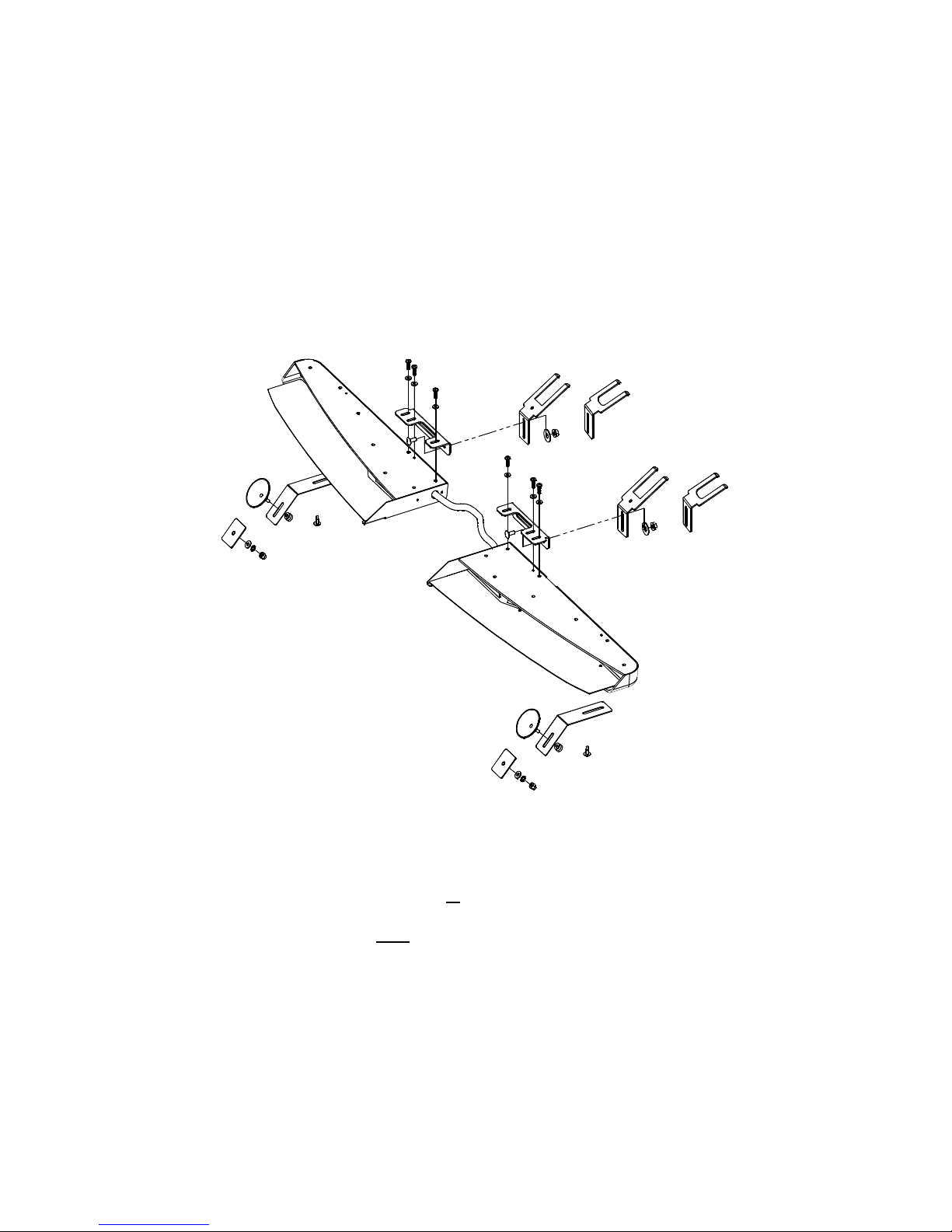
The mounting instructions are divided into two separate sections. If you
are using the Universal Mount, proceed below. If you will be using one of
the vehicle specific brackets, please skip to page 9.
UNIVERSAL BRACKET INSTALLATION
(Model 274-ULB21-U1)
OR
OR
SUCTION CUP
OR
WINDOW ADHESIVE
MOUNT
•
Two different sets of forked brackets are provided. Use the pair of forks
that will require the least amount of adjusting when aligning the light with
the window.
•
The Universal Mount uses either pair of forked brackets, in conjunction
with either a pair of suction cups or a pair of window adhesive mounting
pads (both included).
•
The Forked Brackets must be installed for both the suction cup and
window adhesive mounts.
•
Determine if you can install the Forked Brackets under your visor clips or
if you need to attach them in an alternate fashion and refer to the
appropriate section on pages 6 or 7.
-4-
Page 6
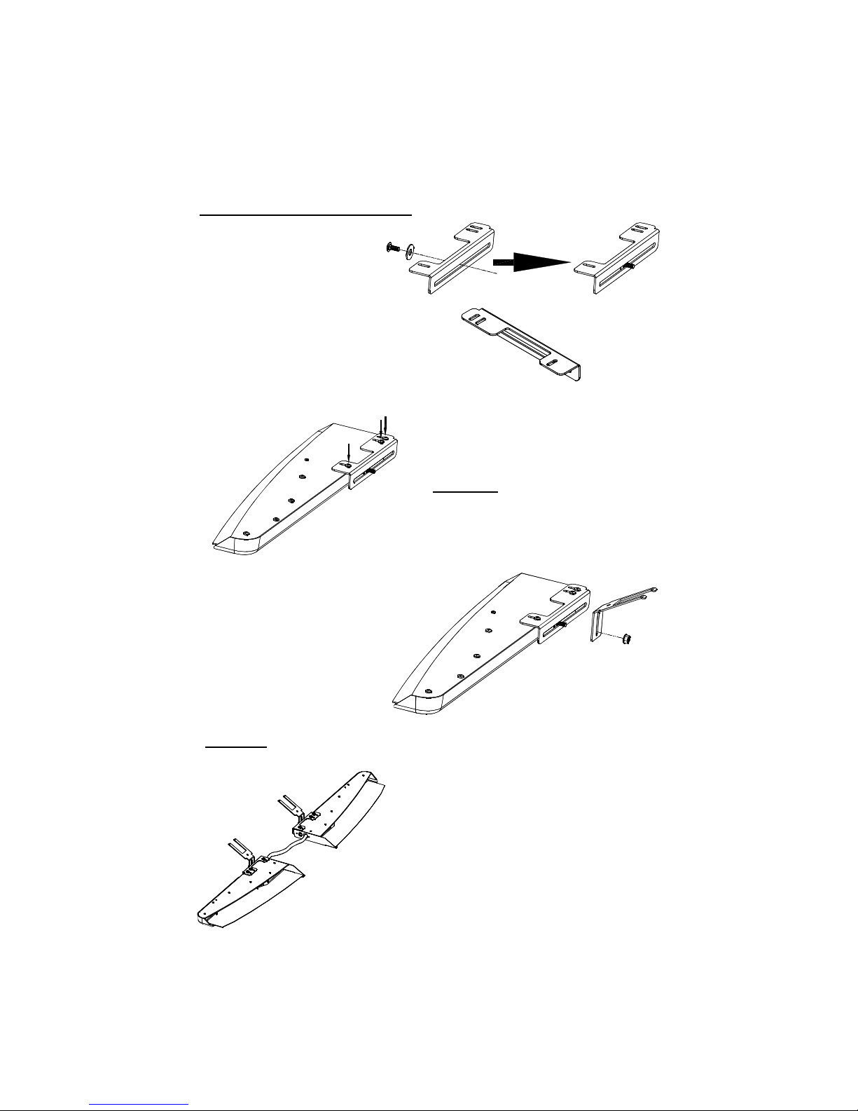
Universal Mounting (CONT'D)
Attach Forked Brackets to Light
1. Insert one of the carriage
bolts through one of the
washers. Please note that
washer is used as a spacer
on the square neck of the
carriage bolt. Slide the bolt
and washer through the
back of the left bracket.
Be sure to select the correct
bracket. The larger flange
should be located towards
the center of the light.
2. Remove three of the #8 x 1/2" selftapping Phillips pan head screws and
use them to install the left attaching
bracket on the light.
CAUTION: Take extreme caution not
to over tighten the screws!!! Over
tightening of the screws can strip the
holes and result in a faulty mount.
3. Once the left attaching bracket is installed
securely on the light, fasten one of the
forked “L” brackets to the attaching
bracket, using the carriage bolt,
a washer, and a nut. Leave
the nut slightly loose to
allow for minor adjustments
during the remainder of the
installation.
CAUTION: Take extreme caution not to over tighten the screws!!! Over
tightening of the screws can strip the holes.
4. Repeat steps 1-3 for the right attaching bracket .
-5-
Page 7
Universal Mounting (CONT'D)
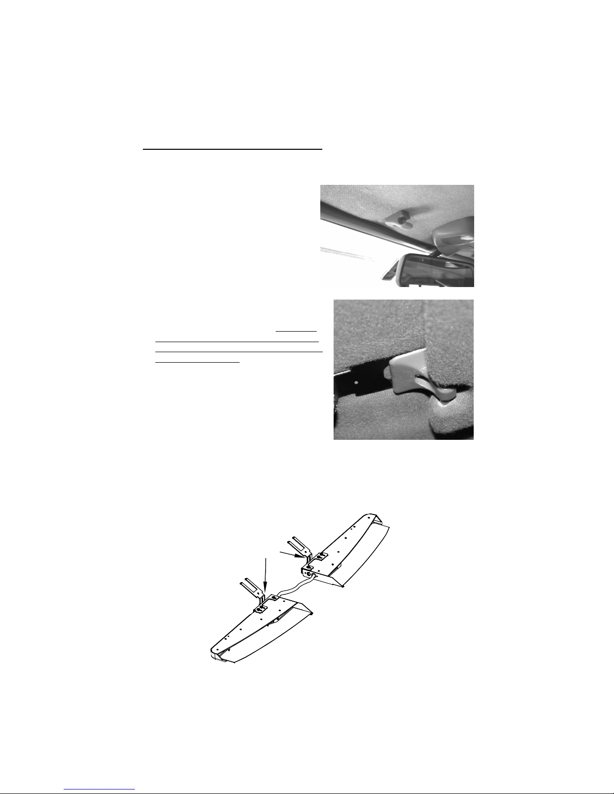
Attach Forked Brackets to Visor Clips
(If you do not have visor clips, or your visor clips will NOT provide a secure mount, or this
method will not work in your vehicle for any other reason, use the alternate method on the
next page.)
1. Standard mounting uses the factory
installed visor clips already located on
the vehicle, in conjunction with the
suction cups or window adhesive
mounts. If you do not have any visor
clips, use the Alternate Mounting
section on the next page
2. Locate the two visor clips on the vehicle.
The style may vary from vehicle to vehicle.
Some styles use only one screw each,
while others may have more. Verify that
both visor clips are a minimum of 3” from
the center of the window, and a maximum
of 8” from the center.
3. Loosen (or remove if necessary) both visor
clips enough that one of the forked brackets
can easily slide under each of them.
4. Slide one forked bracket under each visor clip
and tighten the clip such that it securely holds
each bracket in place.
.
5. Once the brackets are installed securely under the visor clips or with a suitable
fastener, check to see that the bottom of the light is level front-to-back. If it is
not level, remove the light from the visor clips and carefully bend the forked
brackets as necessary. Reinstall the light and check again for levelness.
Repeat this process until the light is level.
Bend here if
necessary
-6-
Page 8
Universal Mounting (CONT'D)
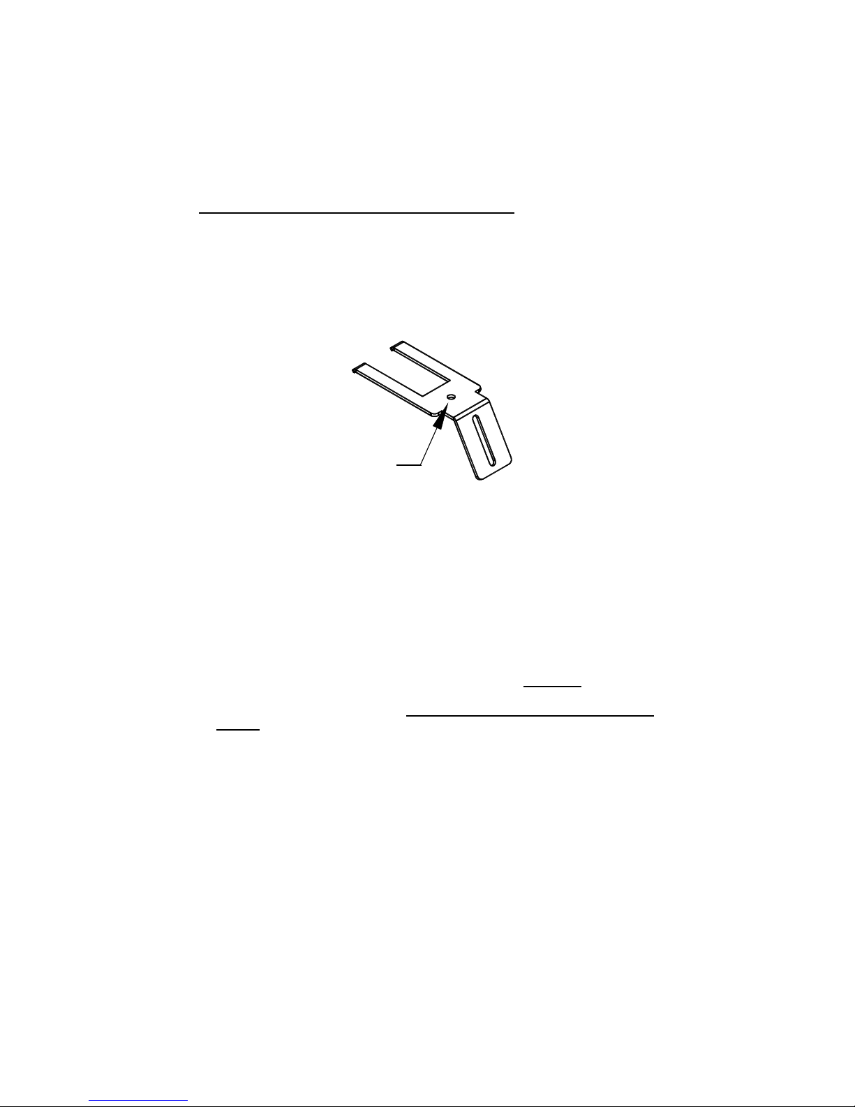
Attach Forked Brackets using Alternate Method
If you are not using the visor clip installation described on the previous page,
continue below.
1. Some vehicles may not have visor clips appropriate for the previously
described installation, or may completely lack any visor clips. An alternate
mounting screw hole is provided in the bracket for these situations. This hole
can be used with an appropriate user supplied screw or other suitable fastener.
Alternate
Mounting
Hole
2. If you are using the alternate mounting screw hole, you will need to locate the roof
brace under the headliner of the vehicle.
3. Once you have located the roof brace, pick an area to mount the brackets (one on
each side) that is a minimum of 3” from the center of your window and a maximum
of 8”.
4. You must then determine an appropriate size screw to penetrate the headliner and
securely mount the brackets to the roof brace. When selecting a screw, take care to
ensure that it is capable of supporting the weight of the light and it will not penetrate
the roof of the vehicle.
5. Carefully drill any necessary pilot holes in your roof brace. CAUTION: Take care to
ensure when selecting a screw and drilling the hole that it is capable of
supporting the weight of the light and that it does not penetrate the roof of the
vehicle.
6. Install the screws through each bracket.
7. If necessary, adjust your light as described in Step 5 on the previous page.
-7-
Page 9
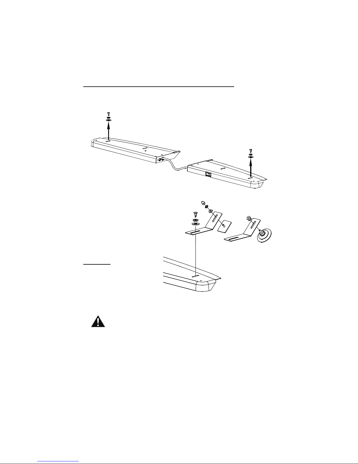
Universal Mounting (CONT'D)
Attach The Suction Cups or Window Adhesive Mounts
1. Remove the two #4 x 1/4" Phillips pan head screws on either end of the bar,
along with the washers and nylon spacers.
Remove outermost screws
from bottom of unit.
(Bottom View)
2. Use the screws to attach the
"L"-Brackets to either end of
the light as pictured to the
right. You may desire to
remove the nylon spacer if
the screw does not securely
fasten to the base.
CAUTION: Take extreme
caution not to over tighten the
screws!!! Over tightening of
the screws can strip the holes
and result in a faulty mount.
or
3. Then use the appropriate hardware (as shown above) to attach either the
Adhesive Pads or the Suction Cups, depending upon your application.
If using the window adhesive:
•
Be sure to use the tube of cleaner to clean both surfaces.
•
After applying adhesive, please allow a minimum of 2-5 minutes
for the pad to adhere to the window before releasing pressure.
•
Allow 24 hours for the adhesive to fully cure before using.
4. Continue to the BAFFLE ADJUSTMENT section on page 11.
-8-
Page 10
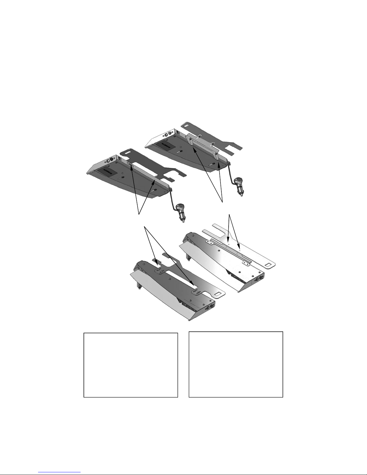
VEHICLE SPECIFIC BRACKET INSTALLATION
(All optional brackets excluding the 274-ULB21-U1)
Determine which bracket style you have, Top Mount or Rear Mount.
Depending upon which vehicle specific bracket you ordered, there are two
different ways the bracket can attach to the light. One style mounts to the top of
the light, one style mounts to the back of the light.
REAR MOUNT
TOP MOUNT
The mounting procedure differs slightly between the two brackets:
Top Mount
1. Mount the visor bracket to the
light.
2. Mount the light and bracket
assembly to the visor clips.
Rear Mount
1. Mount the visor bracket to the
visor clips.
2. Mount the angled bracket to the
visor bracket.
3. Mount stud brackets to light.
4. Mount the light and bracket
assembly to the visor clips
-9-
Page 11
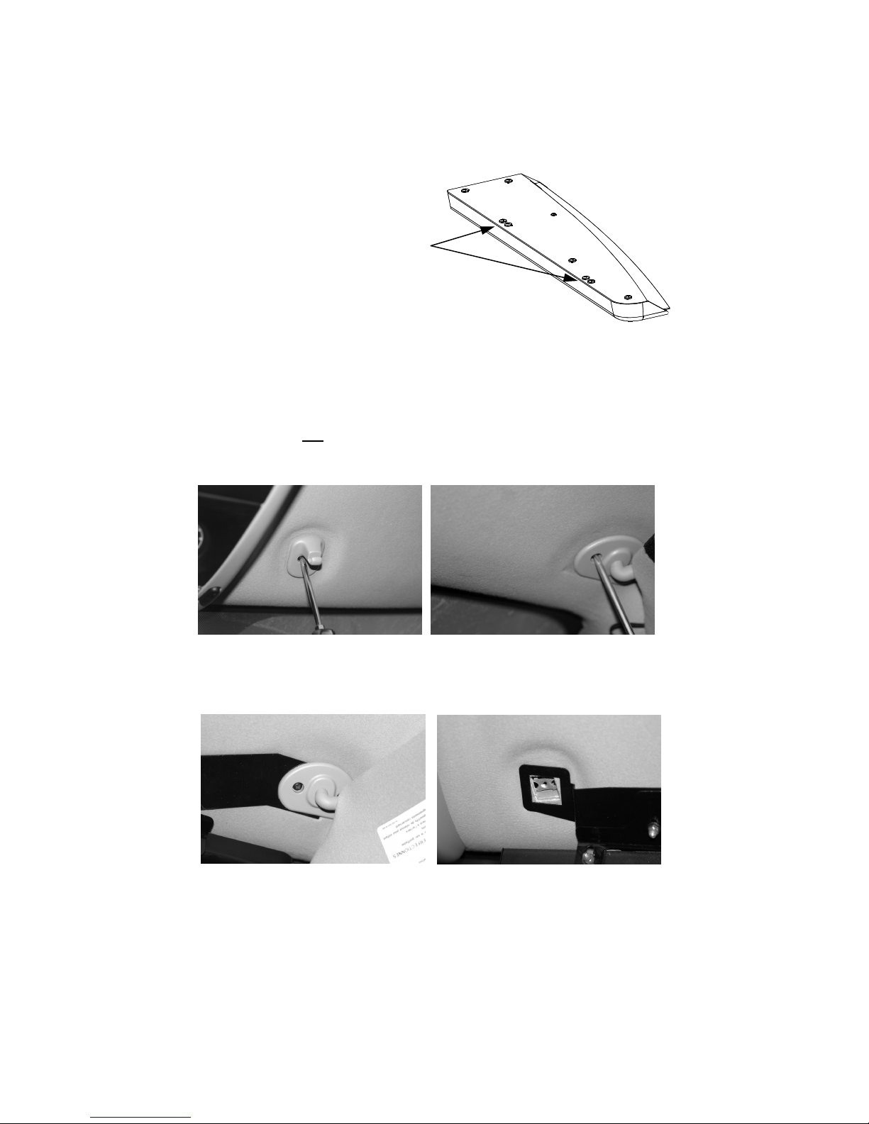
Vehicle Specific Mounting Brackets (CONT'D)
For both the Top and Rear mount
brackets, you will need to remove the two
pairs of screws from each light half as
shown to the right.
TOP MOUNTED BRACKETS
For the rear mounted brackets, skip to the REAR MOUNT section on page 11.
1. Place your bracket over the holes as pictured on the previous page and re-install
the screws, securing the bracket to the light. Do this for both halves of the light,
ensuring the brackets are mounted with the forks towards the outside.
2. Attach the light and bracket assembly to the visor clips as described below.
VISOR CLIP BRACKET INSTALLATION
1. Remove both the driver and
passenger visor clips from
the vehicle.
3. Slide the forked end of the visor
bracket under the visor pivot arm
that you just loosened.
(Passenger’s side shown)
2. Loosen (LOOSEN, DO NOT REMOVE!!)
the three visor pivot arm screws on one
side of the vehicle with appropriate
screwdriver.
4. Align the square hole on the other
end of the visor bracket with the visor
clip hole.
(applies to Top and Rear Mounts)
(Passenger’s side shown)
(Passenger’s side shown)
-10-
Page 12
Vehicle Specific Mounting Brackets (CONT'D)
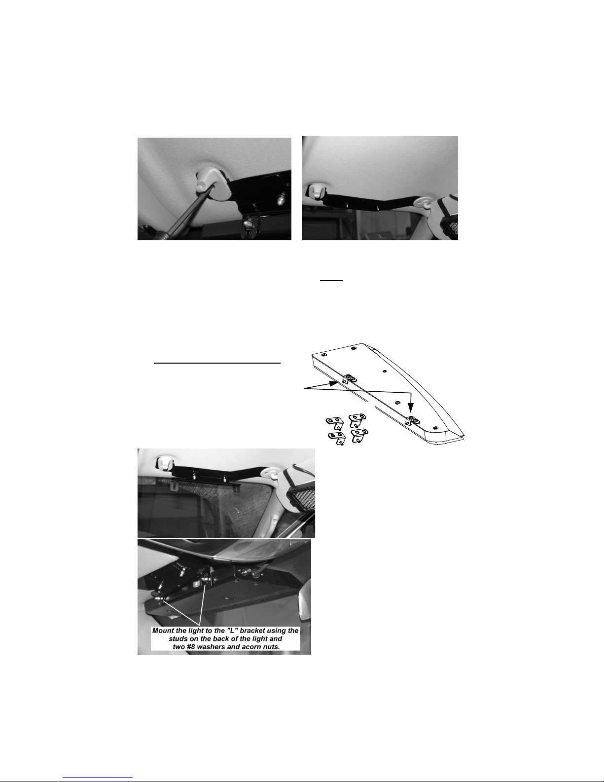
5. Replace and tighten visor clip to
secure the visor bracket to your
vehicle.
(Passenger’s side shown)
6. Tighten the screws on the visor arm
to hold the visor bracket in place.
(Passenger’s side shown)
Note: If you have a Top Mount
Bracket, the light will already be
attached to the bracket.
If you have Top Mount brackets, skip to the BAFFLE ADJUSTMENT section.
REAR MOUNT
1. If you have rear mount brackets,
install the enclosed stud brackets at
each location using the same screws
you removed. The tabs on each stud
bracket should point AWAY from the
cable joining the two halves.
PASSENGER
DRIVER
SIDE
SIDE
2. Install the angled "L" bracket over
the two studs on the visor bracket
as shown to the left. Secure it
using two #8 washers and two
acorn nuts.
Note: You may want to leave the
acorn nuts slightly loose to allow
for easier final adjustments.
(Passenger’s side shown).
3. Attach the light to the "L" bracket
using the two stud brackets.
Secure the light using two #8
washers and acorn nuts as shown
to the left. Note: You may want to
leave the acorn nuts slightly loose
to allow for easier final adjustments.
-11-
Page 13
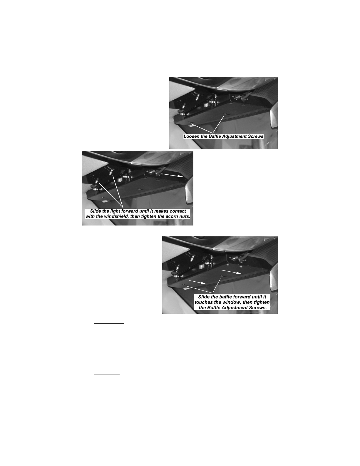
Vehicle Specific Mounting Brackets (CONT'D)
4. Loosen the two Baffle
Adjustment Screws located on
the bottom of the light to allow
the baffle to slide.
shown)
(Driver’s side
BAFFLE ADJUSTMENT (All Models)
5. With the acorn nuts still
slightly loose, slide the light
as close to the front
windshield as possible.
Once it is touching the
window, tighten the two
acorn nuts that secure the
two brackets together.
6. Repeat installation for the
opposite side of the vehicle.
1. After the top of the light is
touching the windshield, slide
the baffle forward until it
satisfactorily blocks any
reflected light.
2. Tighten the Baffle Adjusting
Screws to secure the baffle
in place .
CAUTION: Take extreme caution not to over tighten the
screws!!! Over tightening of the screws can strip the holes.
3. Once all of the brackets are securely tightened, check your mount to ensure the
desired angle is achieved. Stand in front of the vehicle and inspect the light
through the front windshield. The screws may be loosened slightly to allow for any
final adjustments necessary.
4. After all the necessary adjustments are made retighten all the screws.
CAUTION: Take extreme caution not to over tighten the screws!!! Over
tightening of the screws can strip the holes and result in a
faulty mount.
-12-
Page 14
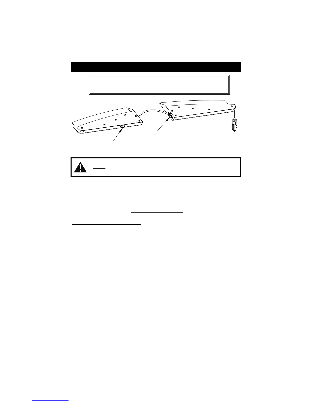
Operating Instructions
CAUTION!!! Once the light is secured, route your cord such that
it does not interfere with the vision of the driver or the operation
of the steering wheel, gear shifter, and/or any airbags.
Pattern Select / Burst Mode
3-Way Mode Switch
Flashing/Off/Steady
All wires connected to the positive terminal of the battery should be fused at the
battery for their rated load. Testing the light before this fuse is properly
installed will void the warranty on the light.
The 3-Way Mode Switch (Flashing/Off/Steady or Pursuit/Off/Takedown)
Steady: (Takedown) mode, the LEDs will not flash, but instead will remain
Flashing: Pursuit mode - the LEDs will flash according to the pattern you have
Pattern Select/Burst Mode Button
This is a momentary switch and has two different functions, depending upon which
mode the 3-Way Mode Switch is in.
3-Way Mode Switch set for Steady (Takedown) Mode:
Pattern Select/Burst Mode will “burst” your LEDs into a super-bright, high-power
mode (takedowns). This mode will activate for approximately 30 seconds then revert
to the standard steady burn mode. Please Note: Immediately after the 30 second
“Burst Mode” has ended, the light will be “locked out” of Burst Mode for 30 seconds.
3-Way Mode Switch set for Flashing (Pursuit) Mode:
Pattern Select/Burst Mode will act as the Pattern Select button. Each time this
switch-button is depressed, the
The
Split Phantom
page):
Indicator LED
Located on the bottom of the right half (passenger side) of the
Phantom
LED will light up.
lit, similar to Takedown lights.
selected (See Flashing (Pursuit) Mode below).
Split Phantom
will cycle to the next pattern.
is designed with thirty-five different patterns (see next
Split
™ is an Indicator LED. When your light is activated in any mode, this
-13-
Page 15

Pattern List
1 Slow Warn *
2 Fast Warn
3 Superfast Warn
4 Warn Fade
5 Pre-Pop Warn
6 All Singleflash
7 Alt. Tripleflash
8 All Tripleflash
9 Alt. Quadflash w/Post Pop
10 All Quadflash w/Post Pop
11 Alt. Quintflash
12 All Quintflash
13 Alt. Pre-pop Quintflash
14 All Flicker
15 Alt. PSU Flicker
16 One Side Pop, Other Side Rapid Fire
17 One Side Rapid Fire, Other Pop
18 Comet 1
19 Comet 2
20 Delta Omega (Flash Rate Sweep)
21 Slow Warn, Superfast Warn
22 All Singleflash, All Flicker
23 Alt. Double, ALT. Quad w/Post Pop
24 All Double, ALL. Quad w/Post Pop
25 Alt Double, Alt. Pre-Pop Quad, Alt. Quad w/Post Pop, Alt Flicker
26 All Double, All Quintflash, All Quadflash w/Post Pop, All Flicker
27 All Quadflash w/Post Pop, All Doubleflash, All Flicker
28 Alt. Pre-Pop Triple, Alt. Doubleflash, Alt Flicker **
29 Alt. Pre-Pops, Alt. Flicker, Superfast Warn
30 Delta Omega, All. Double, All. Flicker
31 One Side Steady---Other side Singleflash †
32 One Side Steady---Other Side Short-Long †
33 Warn Medium (Alt. Long Singleflash) †
34 Alt. Short - Alt. Long †
•
If at anytime you would like to go directly to the Slow Warn (pattern #1), simply
press, and hold the pattern select button for approximately 3 seconds. When the
LEDs flash once, release the button and the light will be in the Slow Warn
pattern.
•
If you would like to place the light back into the default pattern (Pattern 28: Alt.
Pre-Pop Triple, Alt. Doubleflash, Alt Flicker), simply press and hold the pattern
select button until the LED’s flash twice (approx. 6 seconds). Then release the
button and the light should be in the default pattern.
•
Toggle Mode: Pressing and holding the pattern select button until the LED’s
flash three times (approx. 9 seconds) will toggle the “steady side” for patterns 31
and 32.
•
Indicator LED: If you desire, you can disable and re-enable the Indicator LED
by pressing and holding the pattern select button until the LED’s flash four times
(approx. 12 seconds).
35 Cycle All
† = These Patterns meet California Title 13 and SAE J595 specifications in Red and Blue versions of the
model ULB42 only. (ULB42V models DO NOT meet these specs)
* Default Pattern #1
** Default Pattern #2
-14-
Page 16
These lights use state-of-the-art Light Emitting Diode (LED) technology. These warning lights are
comprised of ultra-high intensity LEDs that are controlled by a solid state flasher unit to efficiently
produce light output with lifetimes up to 100,000 hours. Under normal circumstances, you will not
need to replace any LEDs in this light. If any of the LED's in your light do fail, please contact Star
Headlight for arrangements to have them repaired. The flasher unit and heads CANNOT be
serviced in the field and any attempt to do so will void the warranty.
LED FIVE YEAR LIMITED WARRANTY
The manufacturer warrants this LED light against factory defects in material and
workmanship for five years after the date of purchase. The owner will be responsible for
returning to the Service Center any defective item (s) with the transportation costs
prepaid. The man ufacturer will, without charge, repair or replace at its option,
products, or part(s), which its inspection determines to be defective. Repaired or
replacement item(s) will be returned to the purchaser w ith transportation costs prepaid
from the service point. A copy of the purchaser's receipt must be returned with the
defective item(s) in order to qualify for the warranty coverage. Exclusions from this
warranty include, but are not limited to, domes, and/or the finish. This warranty shall not
apply to any light, which has been altered, such that in the manufacturer's judgment,
the performance or reliability has been affected, or if any damage has resulted from
abnormal use or service.
There are no warranties expressed or implied (including any warranty of merchantability
or fitness), which extend this warranty period. The loss of use of the product, loss of time,
inconvenience, commercial loss or consequential damages, including costs of any
labor, are not covered. The manufacturer reserves the right to change the design of
the product without assuming any obligation to modify any product previously
manufactured.
This warranty gives you specific legal rights. You might also have additional rights that
may vary from state to state. Some states do not allow limitations on how long an
implied warranty lasts. Some states do not all ow the exclusion or limitation of incidental
or con sequential damages. Therefore, the above limitation(s) or exclusion(s) may not
apply to you.
NOTE:
Most failures can be traced to wiring and battery problems. Check
"quick-connects” and wiring to insure that correct voltage/polarity is
reaching the electronic strobe light/LED beacon.
If you have any questions concerning this or any other Star product,
please contact our Customer Service Department at (585) 226-9787.
If a product must be returned for any reason,
please contact our Customer Service Department to obtain a
Returned Materials Authorization number (RMA #) before you ship the product to Star.
Please write the RMA # clearly on the package near the mailing label.
-15-
 Loading...