

Page 1

Installation & Reference Manual
What’s new in document ref v32/0912/8
Version 3.2
September 2012
Page 2

Installation and Reference Manual
What’s new in document ref v32/0912/8
Document No. 001a
Version No. V3.2/0912/8
© Copyright SpliceCom Ltd
SpliceCom Ltd
The Hall Business Centre, Berry Lane
Chorleywood, Herts WD3 5EX
Tel: 01923 287700
Website: www.splicecom.com
Page 3

Installation and Reference Manual – What’s New
What’s New
Installation and Reference Manual v3.2/0912/8 1
Contents
This document details the changes to the Installation & Reference manual V3.2/0912/8. Each section has
been listed in the same order that they appear in the manual.
Two Manuals ....................................................................................................................................................... 2
Technical Reference manual .............................................................................................................................. 2
PCS 582G ......................................................................................................................................................... 2
PCS 572G ......................................................................................................................................................... 3
PCS 562 ............................................................................................................................................................ 3
PCS 552 ............................................................................................................................................................ 4
Power over Ethernet considerations .............................................................................................................. 4
PCS 582G Technical Details ............................................................................................................................ 5
PCS 572G Technical Details ............................................................................................................................ 6
PCS 562 Technical Details ............................................................................................................................... 6
PCS 552 Technical Details ............................................................................................................................... 7
Installation and Maintenance Manual ............................................................................................................... 9
View the current licence status ...................................................................................................................... 9
Users ................................................................................................................................................................ 9
Time Plans ..................................................................................................................................................... 10
Creating a SIP trunk....................................................................................................................................... 11
DDI Plans ....................................................................................................................................................... 14
Using the TAPI Driver .................................................................................................................................... 15
Working with Dial Plans ................................................................................................................................ 16
Working with Voicemail ................................................................................................................................ 16
Field Descriptions .......................................................................................................................................... 17
Page 4

Installation and Reference Manual – What’s New
What’s New
2 Installation and Reference Manual v3.2/0912/8
Two Manuals
The Installation and Reference manual has now become two manuals:
maximiser Installation and Maintenance manual
maximiser Technical Reference manual
This documents the changes that now appear in both manuals. In future there will be a “What’s New”
file for each individual document.
Technical Reference manual
PCS 582G
This IP phone provides:
Standard telephony functionality
Graphical colour touch screen LCD interface
Context Sensitive Screen
Ability to display real time video and graphical
information during call
Power - 802.3af Power over Ethernet
2 Port 10/100/1000 Mbps FDX LAN switch – supporting
automatic MDI-MDIX crossover, Diffserv Quality of
Service, 802.1q VLAN and 802.3af Power over Ethernet
2 x USB port – USB 2.0 interface for WiFi and external
keyboard
Headset connection
Wide-angle tilting keypad/display panel
Message waiting/do not disturb “S” LED
Dual Mode – SIP (configured via the Call Server) & H.323
Fully integrated with the LDAP system database for viewing and annotating customer records and
notes
Operator Console Mode available with an Operator Console Licence.
Integral web browser
Can be wall mounted
Can be partnered with PCS 60 or PCS 50
Page 5

Installation and Reference Manual – What’s New
What’s New
Installation and Reference Manual v3.2/0912/8 3
PCS 572G
This IP phone provides:
Standard 12 button telephony functionality
Full colour, backlit, graphics display (240 x 320) with auto-
dimming, context sensitive
Wide-angle tilting keypad/display panel
18 intuitive, multi-functional context sensitive keys
10 fixed function keys
Power - 802.3af Power over Ethernet
2 Port 10/100/1000 Mbps FDX LAN switch – supporting
automatic MDI-MDIX crossover, Diffserv Quality of Service,
802.1q VLAN and 802.3af Power over Ethernet
USB port – USB 2.0 interface for WiFi and external
keyboard
Headset connector
Message waiting/do not disturb “S” LED
Hands free, full-duplex, speaker phone operation
Dual Mode – SIP (configured via the Call Server) & H.323
Fully integrated with the LDAP system database for access to the directories of Users, Departments
and Contacts.
Operator Console Mode available with an Operator Console Licence.
Can be wall mounted
Can be partnered with PCS 60 or PCS 50
PCS 562
This IP phone provides:
Standard 12 button telephony functionality
Full colour, backlit, graphics display (240 x 320) with auto-
dimming, context sensitive
Wide-angle tilting keypad/display panel
9 intuitive, multi-functional context sensitive keys
10 fixed function keys
Power - 802.3af Power over Ethernet
2 Port 10/100 Mbps FDX LAN switch – supporting automatic
MDI-MDIX crossover, Diffserv Quality of Service, 802.1q
VLAN and 802.3af Power over Ethernet
Hands free, full-duplex, speaker phone operation
Headset connector
Message waiting/do not disturb “S” LED
Dual Mode – SIP (configured via the Call Server) & H.323
Fully integrated with the LDAP system database for access to the directories of Users, Departments
and Contacts.
Operator Console Mode available with an Operator Console Licence.
Can be wall mounted
Can be partnered with PCS 60 or PCS 50
Page 6

Installation and Reference Manual – What’s New
What’s New
4 Installation and Reference Manual v3.2/0912/8
PCS 552
This IP Phone provides:
Standard 12 button telephony functionality
Monochrome, backlit, graphics display (64 x 128) with auto-
dimming, context sensitive
8 intuitive, multi-functional context sensitive keys
10 fixed function keys
Power - 802.3af Power over Ethernet
Headset connection.
Fully integrated with system database for viewing and
speed dialling users, departments, contacts and favourites
2 Port 10/100 Mbps FDX LAN switch – supporting automatic
MDI-MDIX crossover, Diffserv Quality of Service, 802.1q
VLAN and 802.3af Power over Ethernet
Hands free, full-duplex, speaker phone operation
Wide-angle tilting keypad/display panel
Message waiting/do not disturb “S” LED
Fully integrated with the LDAP system database for access to the directories of Users, Departments
and Contacts.
Can be wall mounted
Can be partnered with PCS 60 or PCS 50
Power over Ethernet considerations
Power to the PCS 580G, PCS 572G, PCS 570G, PCS 562, PCS 560, PCS 552, IP 530, PCS 410/400 and PCS 100
is provided by Power over Ethernet (PoE). This can be supplied by a third party PoE switch or by the
following methods:
PCS 580/572/570/562/560/552 – via one of the PoE LAN ports on a Call Server or Phone Module, or via
a Single Terminal Ethernet Power Supply (STEPS)
IP 530 - via one of the PoE LAN ports on a Call Server or Phone Module
PCS 410/100 - via one of the PoE LAN ports on a Call server or Phone Module, or via a Single Terminal
Ethernet Power Supply (STEPS)
PCS 400 - via one of the PoE LAN ports on a Call server or Phone Module, or via a Single Terminal
Ethernet Power Supply (STEPS). The PCS 400 can also obtain power via a PCS PSU when it is not
practical to use PoE. Please note that if a PCS 400 is connected to a PoE LAN port on a 5100 or 5108
Call Server the PCMCIA card cannot be used.
Please note that if a STEPS is used with a PCS 580G, PCS 572G or PCS 570G the LAN port (port 1) will not
run at 1G.
PoE LAN ports are provided as follows:
5100 Call Server, 5108 Call Server and 5300 Phone Module – provide 4 x PoE LAN ports supporting the
following combinations:
1 x PCS 580G or
1 x 410/400 or
up to 2 x PCS 572G/570G or
Page 7

Installation and Reference Manual – What’s New
What’s New
Installation and Reference Manual v3.2/0912/8 5
up to 4 x PCS 100/PCS 562/PCS 560/PCS 552/IP 530 or
up to 1 x PCS 572G/570G and 2 x PCS 100/PCS 562/PCS 560/PCS 552/IP 530
PCS 582G Technical Details
Approval
The product is CE compliant according to the European Directives for Safety and EMC.
Safety Caution
The product should not be disassembled. There are no user serviceable parts.
General
Dimensions (mm): 277(w) x 136(d) x 208(h)
Weight (Kg): 1.6
Environmental: 0 to 40°C
85% Relative Humidity, non condensing
LCD
Technology: TFT
Resolution: 800x480
Colours: 262144
Port definitions
LAN port: 10/100/1000BaseT Full Duplex, Auto MDI/MDI-X LAN port and 802.3af compliant power sink
PC port: 10/100/1000BaseT Full Duplex, Auto MDI/MDI-X LAN port.
Handset port: For connection of supplied handset.
Headset port: General 4 pin headset connection. Inner pins connect to earpiece and outer pins connect
to microphone.
USB Host Interface (2 off): USB 2.0 supporting Hi-Speed (480Mb/s), Full-Speed (12Mb/s) and Low-Speed
(1.5Mb/s). Support of devices also depends on driver availability.
Power Supply Considerations
The product is powered from the LAN port.
The PCS582G is a class 3 802.3af compliant powered device, i.e. draws less than 15.4W from the 802.3af
power source.
Care should be exercised when adding USB devices as exceeding the available power will cause the
PCS582G to shut down. Sufficient power is generally available to drive a USB keyboard and mouse. If
greater power is required then an externally powered USB hub may be used.
Page 8

Installation and Reference Manual – What’s New
What’s New
6 Installation and Reference Manual v3.2/0912/8
PCS 572G Technical Details
Approval
The product is CE compliant according to the European Directives for Safety and EMC.
Safety Caution
The product should not be disassembled. There are no user serviceable parts.
General
Dimensions (mm): 277(w) x 136(d) x 208(h)
Weight (Kg): 1.5
Environmental: 0 to 40°C
85% Relative Humidity, non condensing
LCD
Technology: TFT
Resolution: 240x320
Colours: 262144
Port definitions
LAN port: 10/100/1000BaseT Full Duplex, Auto MDI/MDI-X LAN port and 802.3af compliant power sink
PC port: 10/100/1000BaseT Full Duplex, Auto MDI/MDI-X LAN port.
Handset port: For connection of supplied handset.
Headset port: General 4 pin headset connection. Inner pins connect to earpiece and outer pins connect
to microphone.
USB Host Interface: USB 2.0 supporting Hi-Speed (480Mb/s), Full-Speed (12Mb/s) and Low-Speed
(1.5Mb/s). Support of devices also depends on driver availability.
Power Supply Considerations
The product is powered from the LAN port.
The PCS572G is a class 2 802.3af compliant powered device, i.e. draws less than 7W from the 802.3af
power source.
PCS 562 Technical Details
Approval
The product is CE compliant according to the European Directives for Safety and EMC.
Safety Caution
The product should not be disassembled. There are no user serviceable parts.
Page 9

Installation and Reference Manual – What’s New
What’s New
Installation and Reference Manual v3.2/0912/8 7
General
Dimensions (mm): 277(w) x 136(d) x 208(h)
Weight (Kg): 1.5
Environmental: 0 to 40°C
85% Relative Humidity, non condensing
LCD
Technology: TFT
Resolution: 240x320
Colours: 262144
Port definitions
LAN port: 10/100BaseT Full Duplex, Auto MDI/MDI-X LAN port and 802.3af compliant power sink
PC port: 10/100BaseT Full Duplex, Auto MDI/MDI-X LAN port.
Handset port: For connection of supplied handset.
Headset port: General 4 pin headset connection. Inner pins connect to earpiece and outer pins connect
to microphone.
Power Supply Considerations
The product is powered from the LAN port.
The PCS560 is a class 1 802.3af compliant powered device, i.e. draws less than 4W from the 802.3af power
source.
PCS 552 Technical Details
Approval
The product is CE compliant according to the European Directives for Safety and EMC.
Safety Caution
The product should not be disassembled. There are no user serviceable parts.
General
Dimensions (mm): 277(w) x 136(d) x 208(h)
Weight (Kg): 1.5
Environmental: 0 to 40°C
85% Relative Humidity, non condensing
LCD
Resolution
64 x 128
Monochrome shades
2
Page 10

Installation and Reference Manual – What’s New
What’s New
8 Installation and Reference Manual v3.2/0912/8
Port definitions
LAN port: 10/100BaseT Full Duplex, Auto MDI/MDI-X LAN port and 802.3af compliant power sink
PC port: 10/100BaseT Full Duplex, Auto MDI/MDI-X LAN port.
Handset port: For connection of supplied handset.
Headset port: General 4 pin headset connection. Inner pins connect to earpiece and outer pins connect
to microphone.
Power Supply Considerations
The product is powered from the LAN port.
The PCS552 is a class 1 802.3af compliant powered device, i.e. draws less than 4W from the 802.3af power
source.
Page 11

Installation and Reference Manual – What’s New
What’s New
Installation and Reference Manual v3.2/0912/8 9
Installation and Maintenance Manual
View the current licence status
A list of the licences installed on the system together with how many of these licences have been used is
available within Manager by selecting Utilities and then Licences.
The User Licence Status page will display where licences have been allocated for each User. Licences can
also be enabled and disabled via this page.
The Department Licence Status page will display where licences have been allocated for each
Department. Licences can also be enabled and disabled via this page.
The System Licence Status page will display the number of licences installed and being used.
Users
Vision
Each User that is to become an Agent within the Vision Call Centre software will require the following
configuration:
A Voicemail Access Code (which can be configured within the Voicemail page of the User’s
configuration form)
A Remote Working Code (which can be configured within the Telephony tab of the User’s
configuration form) that matches their handset’s Partner Login Code (please refer to the
Configuring an Analogue Extension Port section or the Configuring an IP Phone section for
further details)
Capabilities as described in the Group Membership section of the Vision Call Centre
Configuration Manual
The relevant User can now be configured as an Agent as described in the Vision Call Centre Configuration
manual.
Page 12

Installation and Reference Manual – What’s New
What’s New
10 Installation and Reference Manual v3.2/0912/8
Please note that if the Agents will be hot desking the Partner Login Code must be the same on all
handsets, and therefore, the Remote Working Code must be the same for each User.
Each User that is to use the Supervisor Console application will require the following configuration:
A Voicemail Access Code (which can be configured within the Voicemail page of the User’s
configuration form)
A Remote Working Code (which can be configured within the Telephony tab of the User’s
configuration form) that matches their handset’s Partner Login Code (please refer to the
Configuring an Analogue Extension Port section or the Configuring an IP Phone section for
further details)
The relevant User can now be configured to use the Supervisor Console application as described Vision
Call Centre Configuration manual.
Please note that some Agent and Supervisor Console features may work initially without the above
configuration, however the system will be regularly checking for this information and Agent and
Supervisor functionality will no longer operate if this is not found within the User’s configuration form.
Please refer to the Vision Installation and Configuration manual and Vision Call Centre Configuration
manual for further information on working with Vision.
Time Plans
Running a PHP script with a Time Plan
A PHP script can be run either when the Time Plan is In Hours (active) or Out of Hours (inactive). The
path to this script is entered in either the Script for Active or Script for Inactive fields, as per this example:
Page 13
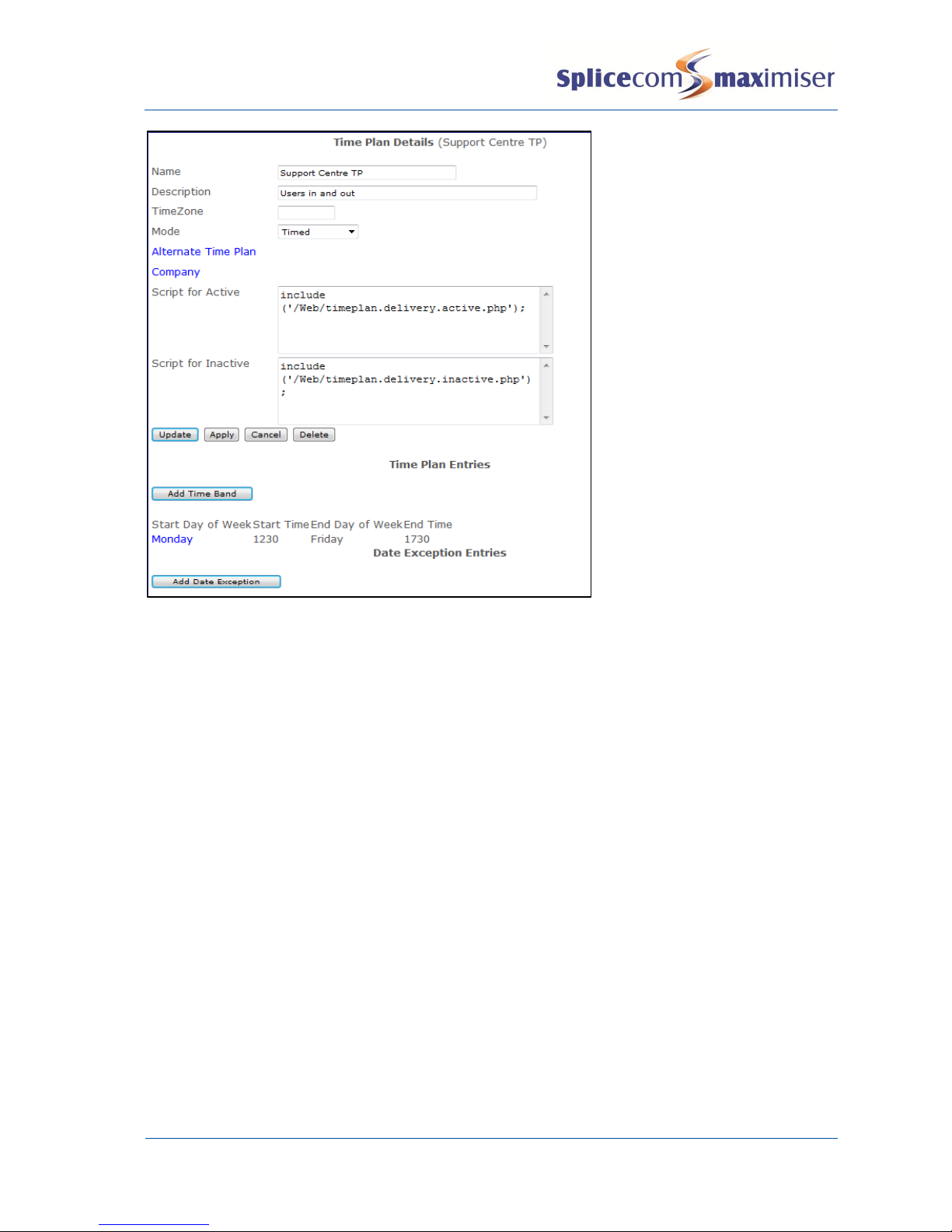
Installation and Reference Manual – What’s New
What’s New
Installation and Reference Manual v3.2/0912/8 11
In this example the scripts are stored in the /Web directory on the Call Server.
Creating a SIP trunk
A Call Server can support SIP Proxy Server and SIP Trunk services and can be configured as follows. Please
note that when using a 4100 Call Server or 4140 Remote Call Server a Voice Compression Module or card
is required to use this facility together with the required number of Trunk licences, one per channel.
1 In Manager select Modules
2 From the Module list select the Add SIP Gateway button
3 In the Name field enter a name to identify this external gateway
4 Enter the IP address of the remote end, or the name, e.g. sip.example.com, if required instead
5 Select Apply
6 Select the Call Server field
7 From the Select Call Server list select the Call Server to which this SIP Gateway is to be registered.
8 Select Update or Apply when ready.
Page 14

Installation and Reference Manual – What’s New
What’s New
12 Installation and Reference Manual v3.2/0912/8
9 From the navigation pane select Trunks
10 Select the Module created above
11 From the Trunks List select Virtual
12 In the Presentation Number field enter the number to be sent on this Trunk. (This may be the
account number supplied by the SIP provider.)
13 Select Apply
14 Select the DDI Call Plan field
15 From the Select DDI Plan list select the DDI Plan required
16 In the Capacity field enter the number of connections to be allowed on this link.
17 Select Apply
18 Select the SIP page
19 From the Compression Type list box select
a G729A 8K – if supported by the SIP Provider, or
b Relay – for G711
20 In the NAT Server field enter
a the IP address allocated by the ADSL provider, or
b if using STUN, the name of the STUN server (provided by the SIP provider)
21 In the NAT Port field enter
a
5060
, or
b
3478
- if using STUN
22 From the NatMode field select Static or STUN
23 If a Registration DNS/IPAddress, User Name and Password have been supplied by the SIP provider
enter this information in the relevant fields otherwise leave the fields blank.
Page 15

Installation and Reference Manual – What’s New
What’s New
Installation and Reference Manual v3.2/0912/8 13
24 Select Update or Apply when ready.
You will also need to configure port forwarding on the ADSL router to forward packets to the IP address of
the Call Server to which the SIP Trunks are registered, typically,
UDP Port 5060 (SIP)
UDP Ports 6300-6699 (Audio)
Page 16

Installation and Reference Manual – What’s New
What’s New
14 Installation and Reference Manual v3.2/0912/8
Please note that SIP providers do not accept Overlap Dialling (default) therefore the LCR Plan entries
routed to a SIP trunk must be configured to collect the digits and send them en-bloc, similar to the
following example for dialling national numbers.
Using the SIP “From” Field
In general this field is left blank however if a provider requires certain information to be presented the
following should be taken into account.
The maximiser system presents <presentation number> <account number>@<module address>
If alternative information is required the follow text strings can be used:
%s = presentation number (e.g. 441923282200)
%c = account number (e.g. 00001234567)
%u = user (e.g. Sam Jones)
so a blank entry is equivalent to:
%s %c@<module address> eg 441923282200@sip.provider.net
An example entry in the SIP “From” Field:
%s@ims.telekomsrbija.com
(To ensure the CLI number is presented)
DDI Plans
Please note:
If the number dialled by the incoming caller is not matched in the relevant DDI Plan the call will be
routed by the Dial Plan configured for the Trunk receiving the call.
Page 17

Installation and Reference Manual – What’s New
What’s New
Installation and Reference Manual v3.2/0912/8 15
Using the TAPI Driver
The TAPI Driver available with the maximiser system enables users to dial directly from their Microsoft
Outlook Contacts. This driver is currently available for Microsoft Windows XP, Vista and Windows 7 32 or
64 bit.
1 Download the TAPI driver from the SpliceCom Technical Forum
2 Unzip the file and
a 32-bit Windows – copy \tspi32\maximiser.tsp into
i. \WINNT\System32, or
ii. \Windows\System32 on the user’s PC
b 64-bit Windows – copy \tspi64\maximiser.tsp into
i. \Windows\System32 on the user’s PC, and
ii. \Windows\SysWOW64 (only required if the TAPI application can configure TAPI settings)
3 On the user’s PC, from Control Panel open Phones and Modem Options
4 Select the Advanced tab and select Add
5 Select maximiser TAPI Service Provider and select Add
6 With maximiser TAPI Service Provider selected, select Configure
7 In the IP Address field enter the IP Address of the Call Server or Phone Module
8 In the Port field enter the Port number to which the user’s handset is connected, eg 5001, 5020 etc
(this will be truncated to 1, 20 etc)
9 In the Access Code field enter the port’s Partner Login Code
10 Select OK and then Close
11 Within Microsoft Outlook open the user’s Contacts
12 Select the Dial icon
13 Select Dialling Options
14 From the Connect Using Line list box select maximiser on
15 Select OK and Close
16 The user will now be able to dial directly from a Microsoft Outlook Contact.
Please note:
The IP address of the Call Server or Phone Module can be viewed within Manager. Select Modules
and then select the relevant Call Server or Phone Module, the IP address is displayed.
Each port on a Call Server or Phone module is given a reference number starting at 5001. Therefore
port 1 is referenced as 5001, port 2 as 5002 etc.
The port’s Partner Login Code can be configured within Manager. Open the configuration form for
the relevant User. Select the entry within the Initial Phone field and amend the Partner Login Code
field as required.
Page 18

Installation and Reference Manual – What’s New
What’s New
16 Installation and Reference Manual v3.2/0912/8
Working with Dial Plans
Dial Emergency Action
Calls made via this Action will be displayed in Warnings.
Working with Voicemail
Call Back the Source
While listening to a message a User can ring back the caller by pressing 0 (zero) provided that the caller’s
CLI was presented with the call. The relevant Dial Plan must also support this call as follows:
If the call made to listen to the message was made on the User’s extension via a Dial Plan entry
or via the User’s DDI the User’s Dial Plan will be used.
If the call made to listen to the Department message was made via the Department’s DDI the
Standard Dial Plan will be used.
If the call made to listen to the Department message was made by a User via a Dial Plan entry the
User’s Dial Plan will be used.
If the call made to listen to the message was made to via a DDI with !CollectVoicemail in the
Translate To field the Dial Plan assigned to the Voicemail Port will be used.
Voicemail Access Code
To ensure the system is not victim to fraudulent use do not use “1234” or “12341234” as a User’s
Voicemail Access Code. Please encourage the Users to use alternative codes to provide a greater level of
security.
Voicemail Callback
Please note:
This facility must be enabled via the relevant Voicemail Port. The Enable Message Call Back field is
disabled by default. Select either Internal (enable call back for messages left via an internal number)
or Internal & External (enable call back for messages left via internal and external numbers).
Page 19

Installation and Reference Manual – What’s New
What’s New
Installation and Reference Manual v3.2/0912/8 17
Field Descriptions
The following lists the new fields available in Manager unless mentioned above.
Users – General page
Alias Telephone Number
64 Digits. A number when dialled that will be routed to this User. For example, a DDI number that
historically was used to ring a colleague on another site. If Users still dial this number it will be routed
directly to this User.
Source Alias Telephone Number
64 Digits. The Extension number to be matched in the relevant DDI Plan, the matching DDI number will
be this User’s outgoing CLI. This will also be the extension number given out when this User makes an
internal call. Please note that this will affect voicemail access for this User. Also used by Vision Call
Centre to enable Outgoing Completion Codes, please refer to the Vision Call Centre Configuration
Manual for further details.
Secure Mode
For future use
Users – Telephony page
Follow Me To
The telephone number to redirect ALL calls to when Follow Me is set. This can be an external number or
internal extension number. To forward calls to a Department precede the extension number with a colon
eg :8000. To forward calls to multiple numbers separate each number with a semi-colon(;), eg
2018;07839283834.
Departments – General Page
Alias Telephone Number
64 Digits. A number when dialled that will be routed to this Department. For example, a DDI number
that historically was used to ring a department on another site. If Users still dial this number it will be
routed directly to this Department.
Enable Callback Script
Enable/Disable. If enabled the callback script can be used with this Department. (ESPSession licences
required.)
Departments - Telephony Page
Wrap Up Time
Default = 1 second. The amount of time (in seconds) given at the end of each Department call. The User
will be unable to receive any further calls within this time. This will allow time for any administrative tasks
at the end of a Department call. The number entered must be 1 or greater.
Page 20

Installation and Reference Manual – What’s New
What’s New
18 Installation and Reference Manual v3.2/0912/8
Trunks – SIP page
Registration User Name
User Name provided by SIP provider. If this field contains an at sign (@) only the text prior to the @
symbol will be used in the “To:” and “From:” fields
National Prefix
Format of national numbers presented by the SIP provider, eg 0 for UK.
International Prefix
Format of international numbers presented by the SIP provider, eg 00
Country Prefix
Format of the country code presented by the SIP provider, eg 44 for UK
Prepend
Format of international numbers presented by the SIP provider, eg 00
Outgoing Prepend
Format of international numbers required by the SIP provider for outgoing calls, eg 00
DDI Plan Entry
Description
128 characters. Text field to enter a description for this entry.
Music Channels
Small Packets
For use with SIP trunks
Modules – Call Server – Call Server page
Email Source Address
The address that emails will appear to come from.
Email Source Name
The name that goes in front of the email address.
SMTP Domain Name
If required for SMTP server authentication
SMTP Username
User name for SMTP server authentication
SMTP Password
Password for SMTP server authentication
Page 21

Page 22

The Hall Farm Business Centre, Berry Lane, Chorleywood, Hertfordshire WD3 5EX Tel: 01923 287700 Fax: 01923 287722
Email: info@splicecom.com Website: www.splicecom.com
SpliceCom
Britain’s leading developer of telephone systems
 Loading...