


Installation & Reference Manual
Version 3.2
April 2010

Installation and Reference Manual
Document No. 001
Version No. V3.2/0410/6
© Copyright SpliceCom Ltd
SpliceCom Ltd
The Hall Business Centre, Berry Lane
Chorleywood, Herts WD3 5EX
Tel: 01923 287700
Website: www.splicecom.com

Installation and Reference Manual
Contents
Introduction ......................................................................................................................................................... 1
Platform Overview .............................................................................................................................................. 2
5 Series Hardware ........................................................................................................................................... 2
4 Series Hardware ........................................................................................................................................... 4
maximiser Handsets ....................................................................................................................................... 6
maximiser Software ...................................................................................................................................... 11
System Architecture .......................................................................................................................................... 15
Installing a System............................................................................................................................................. 21
System Operation ............................................................................................................................................. 24
Manager ........................................................................................................................................................ 24
Configuring System Details .......................................................................................................................... 26
Call Status ...................................................................................................................................................... 27
Call Logging .................................................................................................................................................. 27
Configuring the Call Server .......................................................................................................................... 27
Setting the IP Address of the Call Server ..................................................................................................... 28
Using DHCP .................................................................................................................................................. 29
System Time .................................................................................................................................................. 30
Setting up Administrative Access ................................................................................................................. 31
Using Auto Add Phones ............................................................................................................................... 34
Installing Licences......................................................................................................................................... 35
Connecting a Module .................................................................................................................................. 39
Connecting an Analogue Phone ................................................................................................................. 48
Connecting a PCS IP Phone ......................................................................................................................... 51
Installing PCS Software ................................................................................................................................. 58
Connecting Multiple Call Servers ................................................................................................................. 72
Configuring PBX functionality ........................................................................................................................... 77
Configuring an Analogue Extension Port .................................................................................................... 77
Configuring an IP Phone .............................................................................................................................. 79
Working with Users ...................................................................................................................................... 80
Working with Dial Plans .............................................................................................................................. 114
Working with Groups .................................................................................................................................. 122
Routing calls via a Department .................................................................................................................. 128
Setting up the Contacts Database ............................................................................................................. 141
Using a Time Plan ....................................................................................................................................... 148
Conferencing .............................................................................................................................................. 152
Working with Companies ........................................................................................................................... 155
Working with Trunks ................................................................................................................................... 159
Working with DDI Plans .............................................................................................................................. 169
Working with LCR Plans .............................................................................................................................. 175
Using Area Codes ....................................................................................................................................... 177
Configuring Music Channels...................................................................................................................... 177
Using Events ............................................................................................................................................... 181
Using the TAPI Driver .................................................................................................................................. 183
Internal Web Server......................................................................................................................................... 184
Working with Voicemail .................................................................................................................................. 187
Voicemail Ports ........................................................................................................................................... 188
Licensing ..................................................................................................................................................... 189
Enabling Voicemail for a User .................................................................................................................... 190
Contents
Installation and Reference Manual v3.2/0410/6 i

Installation and Reference Manual
Installation and Reference Manual v3.2/0410/6
Leaving a Message ..................................................................................................................................... 192
Accessing Voicemail ................................................................................................................................... 193
Remote Access to Voicemail ...................................................................................................................... 202
Setting up Voicemail Email ......................................................................................................................... 207
Setting up SMS Alerts ................................................................................................................................. 209
Using voicemail with a Paging Port ........................................................................................................... 209
Voicemail for a Department ....................................................................................................................... 209
Creating an Auto Attendant ....................................................................................................................... 222
Creating VXML Scripts ................................................................................................................................. 225
Call Recording ............................................................................................................................................. 232
Maintaining and Troubleshooting Voicemail ............................................................................................ 237
Importing and Exporting the Configuration .................................................................................................. 240
Data Routing ................................................................................................................................................... 247
Creating a WAN Link ................................................................................................................................... 247
Setting up IP Routes ................................................................................................................................... 248
Setting up PPP ............................................................................................................................................. 248
Setting up Bandwidth on Demand (BOD) ................................................................................................ 249
Maintenance & Troubleshooting ................................................................................................................... 250
Utilities ........................................................................................................................................................ 250
PHP Utility Pages ......................................................................................................................................... 251
System Access ............................................................................................................................................. 251
Reset Switch ................................................................................................................................................ 253
Powering down a Call Server ..................................................................................................................... 255
Rebooting a module .................................................................................................................................. 255
Backing up the Database ........................................................................................................................... 255
Upgrading the System ................................................................................................................................ 258
Initial Configuration Boot Menu ................................................................................................................ 267
Accessing the log files ................................................................................................................................ 268
Using Setnet ............................................................................................................................................... 269
Using Telnet ................................................................................................................................................ 270
Field Descriptions ............................................................................................................................................ 272
Manage Company ...................................................................................................................................... 272
Users ........................................................................................................................................................... 272
Departments ............................................................................................................................................... 282
Groups ......................................................................................................................................................... 288
Time Plans ................................................................................................................................................... 289
Contacts ...................................................................................................................................................... 290
Meet Me Conference ................................................................................................................................. 292
Dial Plans ..................................................................................................................................................... 293
Companies .................................................................................................................................................. 299
Trunks .......................................................................................................................................................... 300
Trunk Groups .............................................................................................................................................. 304
DDI Plans ..................................................................................................................................................... 304
LCR Plans ..................................................................................................................................................... 305
Voicemail Ports ........................................................................................................................................... 305
Music Channels .......................................................................................................................................... 307
Events .......................................................................................................................................................... 308
VXML Scripts ................................................................................................................................................ 308
Auto Attendant ........................................................................................................................................... 310
Modules ...................................................................................................................................................... 310
Phones ........................................................................................................................................................ 316
Contents
ii

Installation and Reference Manual
Unassigned Phones ................................................................................................................................... 319
Unassigned Modules ................................................................................................................................. 319
System ......................................................................................................................................................... 319
Licences ...................................................................................................................................................... 320
Administrators ............................................................................................................................................. 320
Utilities ........................................................................................................................................................ 321
Area Codes .................................................................................................................................................. 322
WAN Links ................................................................................................................................................... 322
Technical Data ................................................................................................................................................. 326
Cable Specifications ................................................................................................................................... 328
Relay Outputs ............................................................................................................................................. 330
Event Inputs ................................................................................................................................................ 331
PCS 580G Technical Details ........................................................................................................................ 332
PCS 570G Technical Details ........................................................................................................................ 332
PCS 570/560 Technical Details ................................................................................................................... 333
PCS 410 Technical Details ........................................................................................................................... 334
PCS 400 Technical Details ........................................................................................................................... 335
PCS 100 Technical Details ........................................................................................................................... 336
PCS 520 Technical Details ........................................................................................................................... 337
PCS 10 Technical Details ............................................................................................................................. 337
PCS 5 Technical Details ............................................................................................................................... 338
Safety Caution ............................................................................................................................................. 338
PCS 505 Technical Details ........................................................................................................................... 339
Voice Compression Card Technical Details ............................................................................................... 339
“Music on Hold” Adapter Technical Details .............................................................................................. 339
“Paging Port” Adapter Technical Details .................................................................................................... 340
Trunk NT Mode Dongles ............................................................................................................................ 341
Glossary ........................................................................................................................................................... 344
Index ................................................................................................................................................................ 349
Contents
Installation and Reference Manual v3.2/0410/6 iii


Installation and Reference Manual
Introduction
max
max
max
max
max
max
max
max
The
imiser business telephony system from SpliceCom provides a breakthrough in integrated voice
communications. Developed from state of the art technology it delivers real life benefits associated with
many traditionally separate components in one single, seamless system, currently supporting 4 to 10,000
IP or analogue extensions. When used in conjunction with SpliceCom’s broad range of Proactive
Communication Station (PCS) phones or applications,
telephone system with their core business applications, so ensuring that the right information can be
delivered to the desktops of the right people at the right time.
Through the use of an innovative architecture,
imiser eliminates the physical and geographical
limitations of traditional telephone systems, allowing great savings to be made on administration,
management and infrastructure costs, through the unification of resource. This approach allows all
businesses, irrespective of size, to benefit from extended communications, and more importantly
protects their initial investment by growing with the business as the need for communication scales and
becomes ever more demanding.
Embracing open standards wherever they exist,
communications as its core. This allows it to be deployed as a simple PBX with sophisticated, yet easy to
use call handling facilities. Alternatively,
imiser can be used to deliver voice as just another
application – albeit a very business critical one – in a fully converged IP network. In the latter case,
imiser’s modular components can be distributed throughout a building, spread across a campus or
even located in different locations, yet still operate and be managed as a single integrated system. With
its ability to integrate seamlessly with multiple applications, independent of platform or location,
imiser delivers the blueprint for business telephony in the 21st Century.
The purpose of this manual is to give a step by step guide on how to install, configure and troubleshoot a
imiser system. The manual starts with a feature guide of each element of a system together with an
understanding of the architecture used and finishes with a complete listing of each configuration field
and its function together with in-depth technical data.
Please note that where the phrase “Call Server” is used this refers to the 5100 Call Server, the 5108 Call
Server, the 4100 Call Server and the 4140 Remote Call Server unless specified.
imiser allows businesses to converge their
imiser utilises a Linux operating system and IP
Introduction
Installation and Reference Manual v3.2/0410/6 1

Installation and Reference Manual
Installation and Reference Manual v3.2/0410/6
Platform Overview
max
5 Series Hardware
max
5100 Call Server
switch
The
imiser system provides a single telephony system for small-to-medium sized companies with
support for 4 to 10,000 extensions. It is a purely IP system supporting either traditional analogue or IP
Phones.
The 5 series
imiser range consists of the 5100 Call Server, 5300 Phone and 5108 Call Server. Each
module is 1u in height and can be mounted in a 19” rack.
The main control unit of the system, this module provides:
• PBX
• Quad BRI (8 channels) / NT ports (2 ports enabled by
licences)
• 2 x PRI (30 channels) / NT / DPNSS ports (1 channel
on each port enabled, the remaining channels can
be enabled by licences)
• 1 x LAN Link port, 10/100 Mbps Full Duplex Ethernet
port for connectivity to existing LAN or dedicated LAN
• 4 x 10/100 Mbps Ethernet ports, integral QoS LAN switch, auto-sensing for MDI/MDIX connectivity and
802.3af Power over Ethernet supported
• 16 x standard analogue (POTS) ports with support for DTMF analogue handsets, PCS 510/505/10/5, fax
machines and modems plus Caller Display support (8 ports enabled by licences)
• IP Router
• H.323 Gatekeeper
• H.323 Gateway
• Hard disk storage for software, LDAP database (supporting 10,000 configuration entries), voicemail,
internal Web Server, Music on Hold and feature licenses
• 1 x power socket for 48 volts PSU supplied as standard
• 2 x Relay inputs for eg burglar alarm
• 2 x External relays for eg door entry system
• 1 x USB port for software upgrade purposes
• Supports H.450.2 (Call Transfer), H.450.4 (Hold), H.450.5 (Park) and H.450.7 (Message Waiting)
• SIP Proxy Server support
• Supports SIP and H.323 trunk services
• Supports NAT Traversal
• Native mode – G.711 64K with echo cancellation
• Can support up to 68 x G.729a Compression channels (requires licences)
• Supports 500 Users (analogue and/or IP)
• Up to 200 Call Servers per system (max 10,000 extensions, analogue and/or IP and max 5,000 trunks)
Platform Overview
2

Installation and Reference Manual
5300 Phone
5108 Call Server
This module provides connection for standard analogue telephones:
• Available as 5315 providing 15 POTS ports or 5330
providing 30 POTS ports
• Support for DTMF analogue handsets, PCS 5/10, fax
machines and modems
• Caller Display support
• On-hook voltage 48V, off-hook current 25 mA, ring
voltage 44V rms
• 4 x 10/100 Mbps Ethernet ports, integral QoS LAN switch, auto-sensing for MDI/MDIX connectivity and
802.3af Power over Ethernet supported
• 1 x LAN Link port, 10/100 Mbps Full Duplex Ethernet port for connectivity to existing LAN or dedicated
LAN switch
• 1 x USB socket, allows wireless LAN connectivity via USB 2.0 WiFi adapter.
• 1 x power socket for 48 volts PSU supplied as standard
• Provided with PCS 60 or PCS 50 application to partner an analogue handset from a Windows or Mac
OSX PC
The 5108 Call Server is designed either for the smaller business or the small remote office as part of a
larger network. This module provides:
• PBX
• Dual BRI (4 channels) / NT ports (1 port enabled by licence)
• 4 x standard analogue (POTS) ports with support for DTMF
analogue handsets, PCS 5/10, fax machines and modems plus
Caller Display support
• IP Router
• 1 x LAN Link port, 10/100 Mbps Full Duplex Ethernet port for
connectivity to existing LAN or dedicated LAN switch
• 4 x 10/100 Mbps Ethernet ports, integral QoS LAN switch, auto-sensing for MDI/MDIX connectivity and
802.3af Power over Ethernet supported
• H.323 Gatekeeper and H.323 Gateway
• Hard disk storage for software, LDAP database (supporting 10,000 configuration entries), voicemail,
internal Web Server, Music on Hold and feature licenses
• 1 x Relay inputs for eg burglar alarm
• 1 x External relays for eg door entry system
• 1 x power socket for 48 volts PSU supplied as standard
• Supports H.450.2 (Call Transfer), H.450.4 (Hold), H.450.5 (Park) and H.450.7 (Message Waiting)
• SIP Proxy Server support
• Supports SIP and H.323 trunk services
• Supports NAT Traversal
• Native mode – G.711 64K with echo cancellation
• Can support up to 8 x G.729a Compression channels (requires licences)
• Supports 8 Users (or 12 Users with a 5108Plus licence – 4 analogue and 8 IP phone users, or 12 IP
phone users)
Platform Overview
Installation and Reference Manual v3.2/0410/6 3

Installation and Reference Manual
Installation and Reference Manual v3.2/0410/6
4 Series Hardware
max
4100 Call Server
4200 Trunk
The 4 series
imiser system is made up of 3 components – 4100 Call Server, 4200 Trunk and
4300 Phone. The 4140 Remote Call Server combines the functionality of all three of these modules in a
single unit. Each module is 1u in height and can be mounted in a 19” rack.
The main control unit of the system, this module provides:
• PBX
• Quad BRI (8 channels) / NT ports
• Optional single PRI (30 channels) / NT / DPNSS port
• IP Router
• 8 port QoS 10/100 Base-T switch
• Rear 10/100 LAN port
• WAN port V.11 - megastream 2 Mb
• H.323 Gatekeeper
• H.323 Gateway
• Hard disk storage for software (10 GB), LDAP database – supporting 10,000 User entries, voicemail,
Internal Web Server, Music on Hold and feature licenses
• 48 volts PSU (so can purchase commercial UPS)
• 2 x Relay inputs for eg burglars alarms
• 2 x External relays
• Supports H.450.2 (Call Transfer), H.450.4 (Hold), H.450.5 (Park) and H.450.7 (Message Waiting)
• SIP Proxy Server support
• Supports SIP and H.323 trunk services
• Supports NAT Traversal
• LAN PWR port to provide Power over Ethernet (PoE) for the PCS 400/100.
• Native mode – G.711 64K with echo cancellation
• Optional Compression card supporting G.729 8K for WAN links
• Supports 300 Users (analogue and/or IP)
• Supports 4 Trunk modules
• Up to 100 Call Servers and Trunk modules per system (max 5,000 extensions, analogue and/or IP)
This module provides additional ISDN and WAN ports:
• Quad BRI (8 channels) / NT ports
• Optional single PRI (30 channels) / NT / DPNSS port
• WAN port V.11 - megastream 2 MB
• 8 port QoS 10/100 Base-T switch
• Integral H.323 Gateway
• IP Router
• LAN Power port for Power over Ethernet
• Up to 4 Trunk Modules per Call Server
• Up to 100 Trunk Module and Call Servers per system
Platform Overview
4

Installation and Reference Manual
4300 Phone
4140 Remote Call Server
This module provides connection for standard analogue telephones:
• Available as 4315 providing 15 POTS ports or 4330
providing 30 POTS ports
• Support for DTMF analogue handsets, PCS 5/10, fax
machines and modems
• Caller Display support
• On-hook voltage 48V, off-hook current 25 mA, ring
voltage 44V rms
• 10/100 LAN port for connection to network
• PCMCIA slot for wireless LAN connection
• Provided with PCS 60 or PCS 50 application to partner an analogue handset from a Windows or Mac
OSX PC
The 4140 Remote Call Server is designed either for the smaller business or the small remote office as part
of a larger network.
• PBX
• 2 x BRI (4 channels) / NT ports
• Optional additional 2 x BRI (4 channels)/NT ports
• Optional PRI (15 channels) / NT / DPNSS port
• 8 x POTS ports
• IP Router
• 1 port QoS 10/100 Base-T switch
• IP WAN port V.11 - megastream 2 Mb (for connection to a Call Server only)
• H.323 Gatekeeper
• H.323 Gateway
• Hard disk storage for software (10 GB), LDAP database, voicemail, Internal Web Server and feature
licenses
• 48 volts PSU (so can purchase commercial UPS)
• Supports H.450.2 (Call Transfer), H.450.4 (Hold), H.450.5 (Park) and H.450.7 (Message Waiting)
• SIP Proxy Server support
• Supports SIP and H.323 trunk services
• Supports NAT Traversal
• Native mode – G.711 64K with echo cancellation
• Optional Compression card supporting G.729 8K for WAN links
• Supports 40 Users (8 analogue plus a further 32 analogue and/or IP)
Platform Overview
Installation and Reference Manual v3.2/0410/6 5

Installation and Reference Manual
Installation and Reference Manual v3.2/0410/6
4400 Voice Compression Module
max
Handsets
PCS 580G
As an alternative to the 64kbps, G.711 voice supported as standard on maximiser, 8kbps, G.729a based
encoding, provides an excellent balance between voice quality and bandwidth efficiency. The 4400 Voice
Compression Module provides 16 channels, of 8 kbps, G.729a based compression and can be deployed
to provide a higher density of calls between 4100 Call Servers/4140 Remote Call Servers over low speed
WAN links.
• 1 x RJ45 port, dual speed, 10/100 Mbps FDX Ethernet
interface with integral LEDs for Link and Data.
• 1 x 48Vdc Power jack.
• Supports G.729a
• Additional 16 channels enabled via a licence, giving
a maximum of 32 compression channels per module
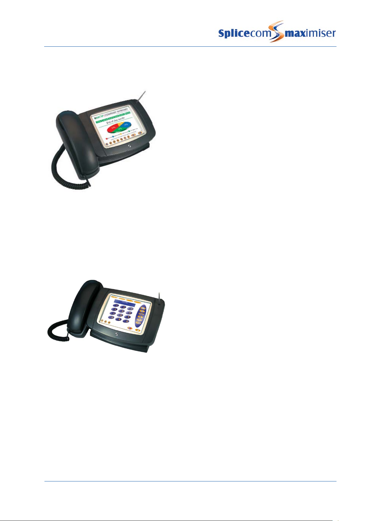
imiser
This IP phone provides:
• Standard telephony functionality
• Graphical colour touch screen LCD interface
• Context Sensitive Screen
• Ability to display real time video and graphical information
during call
• Power - 802.3af Power over Ethernet
• 2 Port 10/100/1000 Mbps FDX LAN switch – supporting
automatic MDI-MDIX crossover, Diffserv Quality of Service,
802.1q VLAN and 802.3af Power over Ethernet
• 2 x USB port – USB 2.0 interface for WiFi and external
keyboard
• Headset connection
• Wide-angle tilting keypad/display panel
• Message waiting/do not disturb “S” LED
• Dual Mode – SIP (configured via the Call Server) & H.323
• Fully integrated with the LDAP system database for viewing and annotating customer records and
notes
• Integral web browser
• Can be wall mounted
• Can be partnered with PCS 60 or PCS 50
Platform Overview
6

Installation and Reference Manual
PCS 570
PCS 570G
PCS 560
This IP phone provides:
• Standard 12 button telephony functionality
• Full colour, backlit, graphics display (240 x 320) with auto-
dimming, context sensitive
• Wide-angle tilting keypad/display panel
• 18 intuitive, multi-functional context sensitive keys
• 10 fixed function keys
• Power - 802.3af Power over Ethernet
• 2 Port 10/100 Mbps FDX LAN switch – supporting
automatic MDI-MDIX crossover, Diffserv Quality of Service,
802.1q VLAN and 802.3af Power over Ethernet
• USB port – USB 2.0 interface for WiFi and external
keyboard
• Headset connector
• Message waiting/do not disturb “S” LED
• Dual Mode – SIP (configured via the Call Server) & H.323
• Fully integrated with the LDAP system database for access to the directories of Users, Departments
and Contacts.
• Can be wall mounted
• Can be partnered with PCS 60 or PCS 50
This IP phone provides the same functionality as the PCS 570 except it has a Gigabit interface providing a
2 Port 10/100/1000 Mbps FDX LAN switch.
This IP phone provides:
• Standard 12 button telephony functionality
• Full colour, backlit, graphics display (240 x 320) with auto-
dimming, context sensitive
• Wide-angle tilting keypad/display panel
• 9 intuitive, multi-functional context sensitive keys
• 10 fixed function keys
• Power - 802.3af Power over Ethernet
• 2 Port 10/100 Mbps FDX LAN switch – supporting automatic
MDI-MDIX crossover, Diffserv Quality of Service, 802.1q
VLAN and 802.3af Power over Ethernet
• Headset connector
• Message waiting/do not disturb “S” LED
• Dual Mode – SIP (configured via the Call Server) & H.323
• Fully integrated with the LDAP system database for access to the directories of Users, Departments
and Contacts.
• Can be wall mounted
• Can be partnered with PCS 60 or PCS 50
Platform Overview
Installation and Reference Manual v3.2/0410/6 7
Installation and Reference Manual
Installation and Reference Manual v3.2/0410/6
PCS 410
PCS 400
This IP Phone provides:
• Standard telephony functionality
• Graphical touch screen LCD interface
• Context Sensitive Screen
• Ability to display real time video and graphical information
during call
• Power over Ethernet support – can be powered via a LAN
port on the Call Server, via the network, or via the optional
dedicated PSU
• 2 Port 10/100 Mbps FDX LAN switch
• USB port for connection of mouse and keyboard
• Internal USB for WiFi
• Headset connection
• Fully integrated with the LDAP system database for viewing and annotating customer records and
notes
• Integral web browser
• Can be wall mounted
• Can be partnered with PCS 60 or PCS 50
This IP Phone provides:
• Standard telephony functionality
• Graphical touch screen LCD interface
• Ability to display real time video and graphical
information during call
• Context Sensitive Screen
• Power over Ethernet support – can be powered via
the network, via the Powered Ethernet PSU or optional
dedicated PSU
• Provides LAN port for PC
• 802.11b PCMCIA Card Slot for Wireless LAN
• USB port for connection of mouse and keyboard
• Headset connection
• Fully integrated with LDAP system database for viewing and annotating customer records and notes
• Integral web browser
• Can be wall mounted
• Can be partnered with PCS 60 or PCS 50
Platform Overview
8

Installation and Reference Manual
PCS 100
PCS 520
The PCS 100 is an IP Phone presented as a conventional business telephone. It provides caller ID, a
dedicated Busy Lamp Field together with pre programmed buttons for simple and easy access to system
features.
• Standard 12 button telephony functionality
• Display of number/name
• 64 x 128 Context Sensitive LCD Display
• 8 Dynamic, Context Sensitive Keys
• Headset connection.
• Powered via the LAN or optional STEPS power
supply
• Fully integrated with system database for viewing
and speed dialling users, departments, contacts
and favourites
• 2 Port QOS switch, single cable to desk.
• Can be wall mounted
• Enhanced volume and speech quality of incoming calls with Automatic Gain Control (AGC).
• Can be partnered with PCS 60 or PCS 50
The PCS 520 is an analogue handset providing the following features:
• Standard 12 button telephone keypad
• 3 line LCD display with contrast settings
• Display of Calling Line Number/Name & Called Line Name
• Dual message waiting/DND indicator
• Visual ringing indicator
• 10 pre-programmed keys
• 10 user definable keys
• Internal directory (100 names/numbers)
• Missed call/Clear/Dial/Pause/Recall/Redial/Speaker/Volume
/Mute keys
• Voicemail guide on handset
• Desktop paging
• Auto Answer
• Headset port
• Powered via the line port
• Can be partnered with PCS 60 or PCS 50
Platform Overview
Installation and Reference Manual v3.2/0410/6 9

Installation and Reference Manual
Installation and Reference Manual v3.2/0410/6
PCS 10
PCS 505
Can be partnered with the PCS 60 or PCS 50
PCS 5
Power over Ethernet PSU
The PCS 10 is an analogue handset providing the following features:
• Standard 12 button telephone keypad
• 3 line LCD display with contrast settings
• Display of Calling Line Number/Name & Called Line Name
• Message Waiting icon
• 10 pre-programmed keys
• 10 user definable keys
• Internal directory (100 names/numbers)
• Missed call/Clear/Dial/Pause/Recall/Redial/
Speaker/Volume/Mute keys
• Headset port
• Powered via a dedicated PSU or with batteries
• Can be partnered with PCS 60 or PCS 50
The PCS 505 is an analogue handset providing the following features:
• Standard 12 button keypad
• Visual call indicator/Message Waiting Lamp
• Headset socket
• Hold/Recall key
• Last number Redial key
• Microphone Mute key
• Headset key
• System Feature Guide
• Voicemail management keys
•
The PCS 5 is an analogue handset providing the following features
• Standard 12 button keypad
• Visual call indicator/Message Waiting Lamp
• Recall/Redial/Mute/Pause keys
• System Feature Guide
• Voicemail management keys
• Can be partnered with the PCS 60 or PCS 50
This is an external power supply for use with the 4100 Call Server and 4200 Trunk Module:
• Providing IP phones, including the PCS 400/100, with power over the LAN when connected to the
integral 10/100 Mbps switch.
Platform Overview
10

Installation and Reference Manual
PCS PSU
Single Terminal Ethernet Power Supply (STEPS)
Voice Compression Card
max
max
Software
PCS 60
• It is connected to LAN PWR port on the back of the 4100 Call Server and/or 4200 Trunk Module
• The LAN PWR port provides power to 2 spare pairs on Ethernet ports
• Up to 8 IP Phones can be powered via the Powered Ethernet PSU.
• Supports the 802.3af Power over Ethernet standard
This is an external power supply providing the PCS 400 IP phones with local power for applications not
using power over LAN, eg Wireless LAN connected phones.
This is an External Power over Ethernet PSU for the PCS 580, 570, 560, 410, 400 and100 or other 802.3af
compliant devices.
Please note:
• if a PCMCIA card is required in the PCS 400 a standard PCS PSU must be used.
• If used with a PCS 580G or PCS 570G the LAN port (port 1) will not run at 1G.
imiser supports G.711 encoding with echo suppression as standard for transporting
voice. Where compressed voice is a requirement, G.729a between Call Servers is supported through
optional internal Voice Compression Cards, one fitted at each end. This feature will support up to 8
channels.
Please refer to page 326 for further technical data on these products.
imiser
This PC application provides the follow facilities:
• Standard telephony functionality
• CLI display
• Context sensitive toolbar
• Fully integrated with the system database for
speeding dialling, viewing and annotating
customer records and notes
• Ability to display real time video and graphical
information during a call
• Operator Console Mode available with an Operator
Console licence
• Can be run as either an IP soft phone or as a
partner to a PCS 580, 570, 560, 410/400, 100, 10, 5
or an alternative analogue handset.
• Available for MS Windows and Apple Mac OS X v10.4 or above
Please refer to the PCS 60 section from page 58 for further details.
Platform Overview
Installation and Reference Manual v3.2/0410/6 11

Installation and Reference Manual
Installation and Reference Manual v3.2/0410/6
PCS 50
PCS Operators Console
Manager
max
Voicemail
This PC application provides the same telephony functionality
as available on the PCS 410/400. PCS 50 can run as an IP Soft
phone or be programmed to partner a User’s
PCS 5/10/100/560/570/580 or existing analogue phone from
their PC.
Versions for Windows and Mac OS X are currently available.
Please refer to the PCS 50 section from page 69 for further
details.
This application combines all of the main PCS 50
functions on a single full screen page for operators
and receptionist. Like the PCS 50 from which it is
derived it can be run as an IP soft phone or as a
Partner to PCS 580, 570, 560, 410/400, PCS 100, PCS
10, PCS 5 or existing analogue phones.
Windows and Mac OS X versions are available.
Please refer to the PCS Operator Console section
from page 71 for further details.
This is a web-based application that is used to view and
configure the database. It can be run from any web
browser (IE v5 or higher, Netscape v6 or higher, Apple
Safari) that can connect to the
Please refer to the Manager section from page 24 for
further details.
The 5100, 5108, 4100 Call Servers and 4140 Remote Call Server all provide integral voicemail & AutoAttendant facilities.
imiser.
Platform Overview
12

Installation and Reference Manual
Enhanced Speech Processing (ESP)
max
• A 5100 Call Server provides up to 16 simultaneous connections, 4 of which are licensed on shipment,
and 1500 hours of message storage
• A 5108 Call Server provides up to 8 simultaneous connections, 2 of which are licensed on shipment,
and 500 hours of message storage
• A 4100 Call Server provides up to 8 simultaneous connections and 30 hours of message storage
• A 4140 Remote Call Server provides up to 4 simultaneous connections and 10 hours of message
storage
This voicemail and Auto-Attendant application can also be run on a standalone Linux PC or Mac PC where
more simultaneous connections or greater storage capacity is required.
A MessageBox licence is required for each User and Department requiring a voicemail facility.
A Voice Processing Port licence is required for each additional simultaneous connection.
Please refer to the Working with Voicemail section from page 187 for further details.
Enhanced Speech Processing is SpliceCom’s advanced multi-layer auto-attendant and Interactive Voice
Response (IVR) system for
imiser. Licensed on a per-port basis ESP utilises standards based VoiceXML
to deliver great flexibility and interoperability for voice processing requirements. ESP allows you to
answer calls, play files, collect DTMF digits, record files and transfer calls. Features and functionality
supported by ESP include;
• Multi-Layer Auto Attendant
• Dial-by Extension
• Voice Forms (DTMF digit and spoken response capture)
• Text-To-Speech (TTS) Conversion
• Reminder/Wake-Up/Alarm Calls
• IMAP Unified Messaging
• Spoken Email Collection & Reply
• Queue Buster
• Call Back When Free
For further information please refer to the Introduction to ESP document available within the Partner area
of the SpliceCom website.
Platform Overview
Installation and Reference Manual v3.2/0410/6 13

Installation and Reference Manual
Installation and Reference Manual v3.2/0410/6
Vision
max
max
max
SpliceCom Vision is a web based application suite
developed from the ground up by SpliceCom to
work with
imiser. Utilising the latest AJAX and Web 2.0
technologies, Vision has been designed to deliver
business critical information, in an easy to
understand manner, wherever and whenever it’s
needed. Vision offers four services; Reports
(historical), Recording (capture) , Live (real-time) &
Mobility (freedom).
For full details on how employ this application
suite with your
the Vision Installation and Configuration Manual.
imiser – and to only work with
imiser system please refer to
Platform Overview
14

Installation and Reference Manual
System Architecture
Working with the System
max
max
max
The system operates entirely around a LAN/IP network environment, eliminating any previous geographic
constraints imposed upon similar systems. The system is constructed with several distinct and discrete
components, all physically independent and operating symbiotically to provide a single seamless system.
All
imiser modules are linked via TCP/IP. Each module is a host on the network with its own IP
address. Therefore each module can be connected via standard CAT 5 cabling, leased line, or Wireless
LAN networking in the case of the Phone Module and the PCS 400. This allows for multi-site networking
with the advantage of only one system to configure & manage – from anywhere. The configuration of
the system is stored on the database which resides on each Call Server; this can be accessed via
Manager. Manager is a web-based application so can be run from any web browser that has an IP
connection to the system.
As the
standard for Voice over IP, is supported. This means that the Call Server acts as the H.323 Gateway. A
gateway is responsible for translating one transmission type into another, so in the case of the Call
Server, for example, it will translate calls received via ISDN so they can travel over an IP network and vice
a versa. The Trunk Module will also provide this functionality. The Call Server also acts as the H.323
Gatekeeper and is responsible for controlling the access into and out of the network – phone
registration, call routing and call logging etc. Quality of Service, also managed by the Call Server, will
ensure that Voice packets have priority over Data packets. This will make sure that a conversation is not
broken up or interrupted.
The configuration of the system is stored on the LDAP database held on the hard disk contained within
the Call Server. LDAP (Lightweight Directory Access Protocol) is the protocol used to store information on
a database that can be searched and queried over a network by any number of users. In the case of the
users to view telephone directories and contact information via a PCS 580, 570/560, PCS 410/410, PCS 100,
PCS 60 and PCS 50. As LDAP is the industry standard for accessing databases future applications will
include access to third party databases.
imiser system is a purely IP system all calls are carried over IP therefore H.323, the industry
imiser system LDAP allows the configuration to be viewed and amended via Manager and allows
System Architecture
Installation and Reference Manual v3.2/0410/6 15

Installation and Reference Manual
Installation and Reference Manual v3.2/0410/6
System Directory
Primary Mode
Secondary Mode
Gatekeeper
Phone Module
Phone Module
Phone Module
Call S erver
Configured with Manager
Cat 5/5e/6
Leased Line
1st Floor
Satellite Site
2nd Floor
Ethernet
via standard Web Browser
connected directly to Call
Server, or via LAN, IP WAN,
VPN etc
The system is powered by a centrally replicated but distributed information directory. In essence this
allows components of the system that are on different continents to act and operate in the same way as
components only inches away from the central unit.
All systems access this database using LDAP (the internet standard for accessing databases) for both
reading and writing to the information.
Call Servers are responsible for holding, distributing and replicating this information. All other modules
must have a direct connection via a LAN to a Call Server.
There are two different scenarios that are constructed:
The Call Server that acts as the Primary administration module and holds the master database for the
entire system. This Call Server is responsible for replicating this database to other Secondary Call Servers.
Secondary Mode indicates that this Call Server will receive a replica of the database from the Primary Call
Server. Any local changes are passed back to the Primary for distribution to all other Secondary Call
Servers.
In all of the above cases non-administrative modules, ie Phone and Trunk modules, obtain their
configuration from a local Call Server, thus they do not need to be configured directly. This allows live
deployment of new modules with minimum complexity.
All Trunks and Phones register with the Gatekeeper in the usual H.323 secure methods. The Gatekeeper
is responsible for all Phone Registrations, Call Routing and Call Logging.
System Architecture
16

Installation and Reference Manual
Trunks
Distributed Phone Modules
Computer Telephony
Distributed Voicemail
Although communication peers (eg phones) pass the voice data directly between them, the Gatekeeper
will control all of the call routing. The Gatekeeper therefore does not require high performance data
capabilities.
The Call Server runs Gatekeeper functionality.
Trunk gateways are registered with the Gatekeeper and act as a resource for the Gatekeeper to route
calls to and from the public PSTN networks. Trunks can be on physically separate modules and
geographic sites.
Clock synchronisation is performed by a combination of buffering and “Clock Count” signalling between
the master system and all slaves.
Call Servers and Trunk Modules run Gateway functionality.
As each Phone Module is LAN connected it can now be distributed geographically within a building or
separate buildings and will only require one cable between the module(s) and the administration system.
This is particularly useful when wiring different floors of a building; only a small number of vertical risers
are needed. Each 100 Mpbs FDX Ethernet connection is capable of handling between 390-780 concurrent
calls, assuming no other traffic. Where non-QoS (Quality of Service) Switches are deployed then it is
recommended that Voice be separated from normal LAN traffic, each Call Server and Trunk module
contains a QoS Switch to allow such segregation. In normal circumstances (simple telephony) it is
recommended that the Ethernet cabling be treated as a new generation of flexible voice cabling and
independently connected, especially with the use of structured wiring and patch panels.
Because each Phone Module is geographically independent so is the Phone oriented computer
telephony. Each Phone Module is responsible for its own handling of a third party TAPI interface.
Additionally the central administrator can have first party telephony ports via TAPI.3.0 and H.323. This is
the method used for external voicemail.
Because voicemail utilises H.323, voicemail platforms can be operating system independent and located
in any appropriate location. Because of the multi-port registration philosophy voicemail can be spread
across many machines increasing the potential capacity of the system. This is especially important when
SAPI (speech recognition) is required.
Call Servers are capable of running an Auto attendant and voicemail service as standard. Voicemail can
also run on a Linux server and will handle storage limited only by the disk space of the machine (approx
0.5 Mbytes per minute).
System Architecture
Installation and Reference Manual v3.2/0410/6 17

Installation and Reference Manual
Installation and Reference Manual v3.2/0410/6
Extendibility
max
Manageable Objects
Users
Departments
Groups
Contacts
Meet Me Conferences
Dial Plans
Time Plans
Although the
imiser platform provides primary applications; Proactive Communication Station,
voicemail etc, the use of H.323 and LDAP means that independent vendors can hook into the system
extending the range of options available. This is especially important in the Call Centre market.
The internal LDAP database contains the following configurable objects.
Each user can make use of the system for communications. These are the primary parameters for all of
the telephony facilities that a user may have. They are distinct from the phone parameters since a user
may login at any phone. Please refer to the Working with Users section from page 80 for further details.
Departments are used to determine the distribution of calls to a particular group of Users. A caller can
dial one number and any available member of a Group can answer the call. A Department is used to
determine what will happen to the call out of hours, if the members of the Group are unavailable or
busy. Please refer to the Routing calls via a Department section from page 128 for further details.
Groups are collections of users and/or capabilities that can be used to identify groups of users. A
distribution group can contain just one user, a thousand users or no users. Alternatively it may have a
capability requirement to automatically select users with a particular skill eg French 80%. Groups may
contain other groups to form “super groups”. Please refer to the Working with Groups section from page
122 for further details.
The Contacts database provides directory lookup information of, eg customers and suppliers. An
incoming call will be alpha tagged if a CLI match is found in the Contacts database and will be displayed
on the PCS, or caller display of the phone. Contacts may also be marked with account codes for billing
and tracking purposes. Please refer to the Setting up the Contacts Database section from page 141 for
further details.
A Meet Me Conference provides the facility to create a conference that can be joined by Users as and
when required. Please refer to the Conferencing section from page 151 for further details.
Dial Plans determine how digits dialled on a User’s handset are handled. Please refer to the Working
with Dial Plans section from page 114 for further details.
Time Plans provide a positive restriction of when activities may happen. In essence a Time Plan defines
when things are allowed to operate by day of the week and time of the day. Please refer to the Using a
Time Plan section from page 148 for further details.
System Architecture
18

Installation and Reference Manual
Companies
Trunks
Trunk Groups
DDI Call Plans
LCR Plans
Voicemail Ports
Music Channels
Events
VXML Scripts
Users, Departments, Contacts and Meet Me Conferences can be assigned to different Companies so that
in a multi-tenancy system Users are unaware of the usage of the system by other businesses. An Auto
Attendant can be assigned to each Company. Please refer to the Working with Companies section from
page 155 for further details.
Trunks are the method used for outgoing or incoming communication with the system whether via ISDN,
SIP, or H.323. Each Trunk port available on the system can be configured individually. Please refer to the
Working with Trunks section from page 159 for further details.
A Trunk group allows the grouping together of multiple Trunks for delivery of calls. This is very useful in
geographically organising the flow of calls, and can also be used to differentiate levels of service, by
keeping spare capacity for high priority calls. Please refer to the Working with Trunks section from page
161 for further details.
Direct Dial In Call Plans determine how incoming ISDN calls will be routed. Please refer to the Working
with DDI Plans section from page 169 for further details.
LCR Plans apply to all calls that will be routed to a trunk via a gateway. It allows the best selection of a
trunk and selection of service providers, based upon the number dialled and time of day. It can also be
used to control the geographic exit point from the network, eg all calls to London numbers would exit via
a London trunk module, but calls to Edinburgh would exit via the Edinburgh trunk module. If a trunk
should be busy or fail then alternate translations and trunks would be used. Please refer to the Working
with LCR Plans section from page 175 for further details.
A Voicemail Port determines the facilities provided by a Call Server’s voicemail service. Where more than
one Call Server is active on a system Voicemail Ports allow different capabilities to be assigned to each
Call Server providing a voicemail service. Please refer to the Working with Voicemail section from page
188 for further details
Music Channels determine how music on hold is played when external calls are placed on hold either
from an internally stored WAV file or via an external source. Please refer to the Configuring Music
Channels section from page 177 for further details.
Events allow web pages to be sent to a PCS 60, PCS 50 or PCS 410/400 to display warning messages,
company information etc. A Relay Input port or a Dial Plan entry can activate an Event. Please refer to
the Using Events section from page 181 for further details.
VXML Scripts provide the ability to create multi-level auto-attendants incorporating features such as
availability based routing, dial by extension, out of hours routing and text-to-speech. Please refer to the
Creating VXML Scripts section from page 225 for further details.
System Architecture
Installation and Reference Manual v3.2/0410/6 19

Installation and Reference Manual
Installation and Reference Manual v3.2/0410/6
Auto Attendant
Modules
max
Phones
Unassigned Phones
Unassigned Modules
System
Licences
Administrators
Utilities
Area Codes
WAN Links
Voicemail provides the ability to create a simple Auto Attendant facility whereby callers can be transferred
to a User or Department from a predefined list of options. Please refer to the Creating an Auto Attendant
section from page 222 for further details.
Modules determine the components that make up the
configured individually. Please refer to the Connecting a Module section from page
imiser system. Each module can be
39 for further details.
Phones are the analogue ports and IP Phones connected to the system. Each phone can be configured
individually. Please refer to the Connecting an Analogue Extension section from page 77 and the
Connecting a PCS section from page 51 for further information.
An Unassigned Phones is an IP Phone requesting registration to the system. Please refer to the Using
Auto Add Phones section from page 34 for further details.
An Unassigned Module is a module requesting registration to the system. Please refer to the Connecting
a Module section from page 39 for further details.
This object gives access to system functionality and system setting such a System Name required for
licence activation and the system Locale. Please refer to the Configuring System Details section from
page 26 for further details.
Licences allow the use of a specific facility on the system or increase the specification of the system.
Each licence purchased is exclusive to one system and one function. Please refer to the Installing
Licences section from page 35 for further details.
The list of administrators of the system. A default Administrator called “Manager” will be created at startup with read/write access to all objects, and will be given a password of “managerpassword”. Please
refer to the Setting Up Administrative Access section from page 31 for further details.
Facilities available for managing, maintaining and troubleshooting the system. Please refer to the Utilities
section from page 250 for further details.
Ambiguous telephone numbers to be matched with incoming CLI when a match is not found within the
Contacts database. The main purpose of these entries is to match the area code part of the CLI so that
caller display will inform the User from which area the call has originated. Please refer to the Using Area
Codes section from page 177 for further details.
WAN Links provide the ability to connect remote systems via a 2Mbps Megastream leased line or via ISDN
dial up. Please refer to the Data Routing section from page 247 for further details.
System Architecture
20

Installation and Reference Manual
Installing a System
Please note
5100 Call Server – Front and Rear view
Input Triggers
Relay sockets
Power socket
Relay sockets
Integral LAN Switch with 4 x
10/100 Mbps Ethernet ports
16 analogue Phone ports
SpliceCom LED
LAN Link
2 x ISDN PRI
4 x ISDN BRI
Disk Drive LED
A 5100 or 5108 Call Server or 4100 Call Server or 4140 Remote Call Server should be the first module to be
powered up; all subsequent modules will join this system.
1 Power up the Call Server using the power supply provided.
2 On the 5100 and 5108 Call Servers the Disk Drive LED will flash to indicate a system check, and on
the 4100 and 4140 Call Servers the NET LED will flash to indicate a system check.
3 The Call Server’s IP address will be 192.168.0.1
4 The Call Server will search for a DHCP Server, if not found, the DHCP server functionality will be
enabled. If the Call Server is connected to a network during power up and finds a DHCP Server its
internal DHCP facility will be disabled.
5 This Call Server will become the Primary Call Server.
6 The SpliceCom LED will become solid when the unit is ready.
Server exists on the network it will attempt to join this system. Ensure the Call Server is disconnected
from the network during power up if this is not required. (Please refer to Connecting Multiple Call
Servers from page
: If a Call Server is connected to a network during power up and it detects that another Call
72 for further details.)
USB Port
Installing a System
Installation and Reference Manual v3.2/0410/6 21

Installation and Reference Manual
Installation and Reference Manual v3.2/0410/6
5108 Call Server – Front and Rear view
4100 Call Server – Front and Rear view
SpliceCom LED
Power socket
Power over Ethernet PSU
10/100 Mbps
4 ISDN BRI
1 ISDN PRI
Input Triggers
Relay sockets
Integral LAN Switch with 4 x
10/100 Mbps Ethernet ports
LED status lights
4 x analogue Phone ports
Power socket
Input Trigger
Relay socket
2 x ISDN BRI
LAN Link
Please note that the front view diagram is incorrect, the first LED is the LINK LED and the second is the
DISK drive LED.
Installing a System
22
LED status lights
Ethernet LAN port
(for future use)
Power socket for
Integral LAN Switch with 8 x 10/100 Mbps Ethernet ports
IP WAN Interface

Installation and Reference Manual
4140 Remote Call Server – Front and Rear view
max
8 analogue phone ports
SpliceCom LED
Power socket
10/100 Mbps
4 ISDN BRI
1 ISDN PRI
IP WAN Interface
Input Triggers
Relay sockets
Once the Call Server has been powered up the following should be noted:
• If the Call Server’s DHCP Server functionality has been enabled the Call Server will give out an address
range of 192.168.0.2 to 192.168.0.250, with 192.168.0.250 being the first address given out. (For
further information on using DHCP please refer to page 29 for further details.)
• When connecting to the LAN ports on the front of the 5100, 5108 or 4100 Call Server straight or
crossover cables can be used because each port automatically changes to MDI/MDX. When
connecting to the LAN port at the back of the 4140 Remote Call Server a crossover cable is required.
• The ISDN Trunk ports available on a Call Server can be used to connect to the exchange or to another
system. Please refer to page 159 for further information.
• The system operates in native mode at G.711 64k with echo cancellation. If the
connected to the company LAN and that LAN is used to carry voice then that LAN must provide Quality
of Service via LAN switches.
• The 5100 and 5108 Call Server and the 4140 Remote Call Server provide 16/4/8 analogue extension
ports respectively. When either of these Call Servers is the first to be installed each port will be
automatically assigned to a User named Extn2001, Extn2002 etc and given an extension numbers of
2001, 2002 etc. Please refer to page 48 for further information on using an analogue extension port.
• Please note that the first 8 analogue ports on the 5100 Call Server are activated, the remaining 8 ports
will require a POTS licence to activate each port. Please refer to page 35 for further information on
Licensing.
LED status lights
Ethernet LAN port
(for future use)
imiser system is
Installing a System
Installation and Reference Manual v3.2/0410/6 23

Installation and Reference Manual
System Operation
Manager
max
It is important to perform an orderly shut
down of the system before power down to ensure all changes are copied to the hard disk and so that the
hard disk is shut down cleanly
max
Running Manager
Working in Manager
The configuration of the
Server. Manager is the application that is used to view and configure this database.
Changes to the configuration made via Manager or by a User via their handset are stored in the RAM and
copied regularly to the hard disk to be stored permanently.
Manager is a web based application which can be run from any Web browser (Internet Explorer v5 or
higher, or Apple Safari v3.2 or higher) that can connect to the
imiser system is controlled and stored on the LDAP database within the Call
- please refer to page 253 for further details.
imiser system.
1 Your PC must have a IP connection to the Call Server
2 Via a web browser, open
ip address of Call Server
http://
3 To view the system’s configuration administration access is required. By default, full access is
available by logging in when requested as follows:
User Name = Manager
Password = managerpassword
/manager eg http://192.168.0.1/manager
For security, it is advisable to at least change the password for this Administrator once access has been
achieved. Please refer to the Setting Up Administrative Access section from page 31 for further details.
On opening Manager a list of the configurable objects on the database is displayed in orange within the
navigation pane on the left hand side (please refer to the Manageable Objects section from page 18 for
a description of each object). A single click on one of the objects will display a list of the relevant entries
in the database. The User’s list is displayed by default.
System Operation
24 Installation and Reference Manual v3.2/0410/6

Installation and Reference Manual
Navigate within a list of entries
item.
Configure an entry
The following options will assist you to navigate and configure the database:
Display the next page of entries
Display the previous page of entries
Display the first page of entries
Create a new entry. The new entry will appear at the bottom of the list and will be called, for
example, newDepartment, newUser, newLicence etc. Select this entry to configure the new
To open, view and edit an entry click on the blue link
To save the changes and return to the previous screen
To save the changes and remain in the current entry.
To return to the previous screen. If changes have been made these will not be saved.
To delete the entry currently displayed. A confirmation message will be received.
When a list of entries is displayed the Search box will be available at the
top of the navigation pane. Enter the specific entry you wish to find in
the Search box and then select Find or press Enter. The entry required
will appear at the top of the list. If the Search box is empty, the Find
button will take you to the top of the list.
To delete the current entry within the field
System Operation
Installation and Reference Manual v3.2/0410/6 25

Installation and Reference Manual
for this particular entry. The Cancel button will return you to the previous screen.
Configuring System Details
An entry may consist of more than one page and the names of these pages are
display at the top of the screen. Click on the page name to access that page. Use
the Apply button to save a change in one page before moving to another page.
When a field name is displayed in blue the entry for this field can be selected from a
list. Click on the field name and select the new entry required. The Cancel button will
return you to the previous screen. The Clear button will delete the entry and leave
the field empty.
If an entry for a field is orange, clicking on this link will display the configuration form
The System Details form of the configuration is used to enter information to identify the system such as
the customer’s name, the supplier’s name and any other text that will help to distinguish the system. If
licences have been purchased the text entered must match that provided with the licences. For further
information please refer to the Installing Licences section from page 35.
1 In Manager, click on System
2 The System Details form will be displayed.
3 Enter a name for your system in the System Name field. Do not use punctuation in this field. This
field is useful to identify the system for troubleshooting purposes. If you have purchased licences
enter your given System Name. (This information will appear on the right hand side of the
Manager screen at the top and bottom once this entry has been updated.)
4 The Supplier field is provided purely for information unless licences have been purchased. Enter
the Supplier Name provided with the licences. (This information will appear on the left hand side of
the Manager screen at the bottom once this entry has been updated.)
5 The Description field is provided purely for information to help you identify the system. This
information will appear on the left hand side of the Manager screen at the top.
6 The System Locale field will determine the language used for voicemail, ring sequences and Caller
Display.
7 Select Update or Apply when ready.
For information on the use of the Call Logging Password please refer to the Call Logging section from
page 27.
For information on the use of the Diagnostic Engineering Password, Web Password and Maintainer
Password please refer to the System Access section on page 251.
System Operation
26 Installation and Reference Manual v3.2/0410/6

Installation and Reference Manual
Call Status
Source
Target
Connected to
Call Logging
Changing the Call Logging Password
Configuring the Call Server
Call Status can be accessed in Manager by selecting Utilities and then Call Status. This application allows
all calls on the system to be viewed.
number dialled
displayed if matched to the number dialled
: Name and extension number of the User making the call
: The number dialled by the Source. The User or Contact name will be displayed if matched to the
: The number the Source was actually connected to. The User or Contact name will be
Call information to be used by third party call logging applications can be obtained from the system via
Telnet to port 4001.
Please refer to the Call Logging Format document available from Marketing for details on the description
of each field.
The Call Logging Password is configurable within Manager and can be used to protect access to the call
logging data.
1 In Manager select System
2 In the Call Logging Password field enter the password required.
3 Select Update or Apply when ready.
No logging output will occur without the Call Logging password being received (new line terminated).
The password must be transmitted in one block/packet.
The Call Server can be configured within Manager by selecting Modules and then the Call Server. The
Module Details form for that Call Server will appear.
System Operation
Installation and Reference Manual v3.2/0410/6 27

Installation and Reference Manual
Setting the IP Address of the Call Server
The Call Server’s Name can be changed to help identify the Call Server. The module’s hardware ID (Serial
Number) is displayed together with its IP address and the current version of software being run on this
Call Server.
The Flash LED button will instruct the Call Server’s SpliceCom LED to flash 20 times. This feature is useful
when multiple Call Servers are being used on a system and will identify the physical Call Server from its
configuration form. For information on working with multiple Call Servers please refer to page 72.
For further information on upgrading the software on a Call Server please refer to Upgrading a System
from page 258. For further information on using the Module Status field please refer to Connecting
Mulitple Call Servers on page 72.
By default, a Call Server will have an IP address of 192.168.0.1. To change this address the following
configuration can be made:
1 In Manager, select Modules
2 From the Modules list select the Call Server required
3 The Module Details form for that Call Server will be displayed.
4 Within the IP Address field enter the IP Address to be used by the Call Server.
5 Select Update or Apply when ready.
6 Reboot the Call Server (please refer to page 255 for information on how to reboot a Call Server.)
Please note:
• If the Call Server has DHCP enabled (as described below) and this IP address is not on the same
network as the DHCP Start and End Address DHCP will not be operational.
• If the Call Server has DHCP disabled the DHCP Base Address and Base Mask must be configured to
match the network that the Call Server is on.
System Operation
28 Installation and Reference Manual v3.2/0410/6

Installation and Reference Manual
Using DHCP
(This is the recommended option if DHCP is being provided
from another vendor)
A list of each module’s IP address
can be viewed in Manager by
selecting Utilities and then IP
Addresses.
During power up a Call Server will search for a DHCP Server, if not found, its internal DHCP server
functionality will be enabled and will give out an address range of 192.168.0.1 to 192.168.0.250. If the Call
Server finds a DHCP Server the DHCP facility will be disabled.
To change this default configuration the following changes can be made.
1 In Manager, select Modules
2 From the Modules List select the Call Server.
3 The Module Details form for that Call Server will be
displayed.
4 At the top of the form select the Call Server page.
The Call Server Details form will appear.
5 From the DHCP Server Mode list the following
options can be selected:
a Enable – this is the default entry. The Call
Server will act as the DHCP server using the IP
Address range specified in the DHCP Start
Address and DHCP End Address fields.
Please note: If another DHCP Server is
detected on the network and the Call Server is
rebooted it will continue to use 192.168.0.1or
it’s previously configured IP Address and
disable its own DHCP Server which means it
will no longer give out IP addresses.
If the DHCP Server mode is re-enabled having previously been disabled, the Call Server will
firstly check whether another DHCP Server exists on the network. Only if it does not receive
an IP address will it become a DHCP Server.
b Disable – DHCP is disabled; the Call Server will use the IP address entered in the IP Address
field within the General page.
c Client – the Call Server will act as the DHCP client obtaining an IP address from a DHCP Server
on the network.
6 The DHCP Start Address and DHCP End Address fields specify the IP address range for the system
when the DHCP Server Mode is set to Enable. (Please note that these fields are irrelevant if the
DHCP Server Mode is set to Disabled.)
System Operation
Installation and Reference Manual v3.2/0410/6 29

Installation and Reference Manual
System Time
7 Select Update or Apply when ready.
8 Reboot the Call Server (please refer to page 255 for information on how to reboot a Call Server.)
Please note:
• Using the default configuration 192.168.0.250 will be the first IP address to be given out, followed by
192.168.0.249 etc.
• On initial connection a PCS 580, 570, 560, 410, 400 and 100 will obtain its IP address from a DHCP
server.
• On initial connection a Phone Module will obtain its IP address from a DHCP server.
The System configuration form displays the current date and time used by the system. This setting can be
changed as follows:
1 In Manager, select Utilities
2 From the Commands list select Set Time
3 Enter the date and time required
4 Select Update when ready.
5 This information will be sent and updated on all handsets on the system
Please note:
• The system will take into account British Summer Time.
• If multiply Call Servers are being used on one system the above time will be the time used by the Call
Server whose Manager is being viewed. Each Call Server can have a different date and time. This
information will be sent and updated on all handsets registered to the specific Call Server.
A Time Zone can be set when the time displayed in, for example, call logging information needs to be
identified with its Time Zone. This is useful when, for example, one maximiser system with multiple Call
Servers is working across multiple countries or states and the time of a call needs to be identified with its
correct Time Zone. (For further information on working with multiple Call Servers please refer to page
72.)
Each Call Server can have a different Time Zone and is configured as follows:
1 Open Manager on the Call Server to be configured
2 Select Utilities
3 Under Commands select Set Time
4 From the Time Zone list box select the option required
5 Select Update when ready.
6 Reboot the Call Server (please refer to page 255 for further information)
Please note: Setnet can be used to set the time zone for a specific Phone Module. For further
information please refer to the Using Telnet section from page 270.
System Operation
30 Installation and Reference Manual v3.2/0410/6

Installation and Reference Manual
Setting up Administrative Access
Default Administrator
Additional Administrators
Creating a new Administrator
By default administration access to the database via Manager is available by logging in as “Manager”
using the password “managerpassword”. This Administrator has full access to the database.
It is recommended that at least the Password be changed to ensure security of the system.
1 In Manager, select Administrators
2 The Administrator List will be displayed
3 Select Manager
4 In the Password field enter the password required
5 Select Update or Apply when ready
Please note: This default Administrator, Manager, gives Authorised Access to new Administrators as
described below. It is therefore recommended that Manager is not deleted.
Additional administrators can also be created to enable staff to log on to Manager but have limited
access to the configuration. A new administrator can be created as follows.
1 In Manager, select Administrators
2 The Administrator List will be displayed
3 Select the Add button
4 Enter the name required for the new Administrator
5 Enter a description if required to further identify this Administrator
6 Enter the password to be used by this Administrator
7 Tick Show Enabled. This will enable the use of the Show tick boxes below. If not ticked this
Administrator will have full access to the database (dependent on the rights and access allowed).
8 Tick the relevant box beside the section of the database to which this administrator is to have
access eg Show Users, Show Departments etc
9 If you wish this Administrator to be able to create and/or delete entries within the section of the
database selected above tick the relevant box, eg Add/Delete Users, Add/Delete Departments.
This option will display the Add button within a list and the Delete button within a specific entry.
(Please note that the Show option allows administrators to amend an entry even though
Add/Delete is not selected (dependent on the rights and access allowed).)
10 Select Apply
System Operation
Installation and Reference Manual v3.2/0410/6 31

Installation and Reference Manual
Assigning rights to the Administrator
Authorising the Administrator
11 If you wish the administrator to be shown a specific page of the database on opening Manager
from the Default Page list box select the page required, eg Contacts.
12 Select Apply
13 Within the Rights section at the bottom of the page select the Add Right button. A new entry will
be displayed providing full rights to the database dependent on the options selected above.
14 Select Update when ready.
15 From the Administrator List select Manager
16 Within the Authorised Access section select the Add Access button
17 Select the Administrator field
18 From the Select Administrator list select the administrator created above. (This entry will provide
full rights to the database dependent on the options selected within the Administrators
configuration form.)
19 Select Update or Apply when ready.
System Operation
32 Installation and Reference Manual v3.2/0410/6

Installation and Reference Manual
View the configuration logged on as the new Administrator
Creating an Administrator for PCS 60 Operator Console Mode
20 Open Manager via your web browser.
21 In the User Name field enter the name of the new
Administrator and enter this Administrator’s password.
22 The Administrator logged in will only have access to the
sections of the database configured above.
Please note: as the default Administrator, Manager, gives Authorised Access to new Administrators it
recommended that Manager is not deleted.
When a User is using PCS 60 in Operator Console Mode the operator can also be given the ability to
change a User’s DND and Forwarding settings via their Favourites. To enable this facility the operator will
require an Administrator name and password.
1 Follow steps 1 to 7 above to create an new Administrator.
2 Select the Show Users option. This is the minimum option required for this facility to be available.
3 Follow steps 13 to 19 above to enter the Rights and
Access levels for this Administrator.
4 Within the PCS 60 application enter the Administrator
Name and Password in the PCS 60 Preferences
dialogue box.
For further information on please refer to the PCS 60 Operator Console Mode section on page 68 and to
the PCS 60 User Manual.
System Operation
Installation and Reference Manual v3.2/0410/6 33

Installation and Reference Manual
Creating an Administrator for a Company
max
Using Auto Add Phones
Turn On/Off Auto Add Phones
Manually register a Phone Module during installation
If the
imiser system is using the Companies feature you may wish an Administrator only to have
access to the entries relating to a specific Company. In this case within the required Administrator’s
configuration form select the Company field and select the required Company from the Select Company
list.
For further information on Companies please refer to page 155.
This feature determines whether phones (analogue or IP) will be able to automatically register with the
system.
If turned on (default), each Phone Module and IP Phone will be able to automatically register with the
Call Server, each port and phone will be listed in the configuration and a User automatically created.
If turned off, each Phone Module and IP Phone must be manually registered on the system
1 In Manager, select Modules
2 Select the Call Server
3 Select the Call Server page.
4 In the Auto Add Phones check box tick to turn on or untick to turn off this feature.
If the Auto Add Phones feature is turned off a Phone Module must be manually registered during
installation as follows:
1 In Manager select Unassigned Modules
2 The Phone Module will be displayed together with its MAC address
3 Select this link
4 The Module Status field will display Available
5 From the Module Status list box select Member
6 Select Update or Apply when ready
7 This unit will now be listed under Modules
The same method is used when installing a Trunk Module.
Please refer to the Connecting a Phone Module section from page 39 for further details.
System Operation
34 Installation and Reference Manual v3.2/0410/6

Installation and Reference Manual
Manually register a PCS 580/570/560/410/400/100 during installation
Manually register a PCS 60 IP Phone or PCS 50 IP Phone during installation
Installing Licences
max
max
If the Auto Add Phones feature is turned off an IP phone must be manually registered during installation
as follows:
1 In Manager select Unassigned Phones
2 The MAC address of the PCS will identify the unit connected. Click on the unit required
3 From the Status list box select Member
4 Select Update when ready
5 The unit will now appear under Phones
Please refer to the Connecting a PCS section from page 51 for further details.
If the Auto Add Phones feature is turned off a PCS 60/50 IP phone must be manually registered during
installation as follows:
1 In Manager select Unassigned Phones
2 The hardware address of the PC will identify the PCS 60 to be connected. Click on the entry
required.
3 From the Status list box select Member
4 Select Update when ready
5 The PCS 60/50 will now appear under Phones, identified by the hardware address of the PC
Please refer to the Connecting a PCS section from page 51 for further details.
Certain functionality of the
licence in order to activate the relevant facility.
Each User created on the system requires a licence. There are two types of User licences either an IPUser
licence or an IPVirtualUser licence. An IPUser licence will be required to create a User who will be
assigned to a physical telephone. By default the
which can be used for testing purposes. When a Call Server or Phone Module providing analogue ports
is installed this is automatically supplied with the required number of IPUser licences and the
corresponding number of analogue phone Users automatically created can utilize the system without
any additional configuration. If further Users are to be created when connecting, for example, a PCS 60
(IP Phone), PCS 50 (IP Phone), PCS 580, 570, 560, 410/400 or 100 additional IPUser licences can be
purchased. An IPUser licence will also be required to create a hot desking User as this User will be
logging on to a physical handset.
An IPVirtualUser licence is required to create a User that requires PBX functionality but does not require a
physical telephone. For example, where a company offers virtual office facilities, voicemail and
forwarding features are required but the customer will not be using a physical telephone. There is no
limit to the number of IPVirtualUser licences that can be run on a Call Server.
An OperatorConsole licence is required for each User who will be using the PCS Operators Console
application or the PCS 580/570/560/60 in Operator Console mode. Please note that this is a per-user
imiser system requires the purchase and installation of the appropriate
imiser system is supplied with one IPUser licence
System Operation
Installation and Reference Manual v3.2/0410/6 35

Installation and Reference Manual
max
licence not a concurrent-usage licence. Please refer to the PCS 60 Operator Console Mode section from
page 68 for further details.
To provide a User with voicemail facilities a MessageBox licence is required. On purchasing a 5100 Call
Server or 4140 Remote Call Server 10 MessageBox licences are provided. A 5108 Call Server is provided
with 5 MessageBox licences. A 4100 Call Server is provided with 30 MessageBox licences. Further
MessageBox licences can be purchased to increase this number, up to 1,000 per system when using
embedded voicemail or up to 100 on a standalone 4140 Remote Call Server and up to 50 on a standalone
5108 Call Server. MessageBox licences are also required to provide a Department with voicemail
functionality. Please refer to the Voicemail section on page 187 for further details. (Please note: a list of
which Users and Departments have been assigned MessageBox licences can be viewed in Manager by
selecting System and then Mailbox Licences. Please refer to page 238 for further details.)
A Voice Processing Port licence will enable an additional port/simultaneous voicemail connection on a
5100 or 5108 Call Server. The relevant number of licences will also be required to run the voicemail
application from a standalone Linux PC or server. One licence is necessary for each connection required.
Please refer to the Working with Voicemail section from page 187 for further details.
To provide Auto Attendant/IVR functionality beyond the single layer provided as standard on
imiser,
an ESPSession licence allows a single channel to be enabled. Enhanced Speech Processing (ESP) is a
voicemail function and can run on the Call Server (up to eight licences), Remote Call Server (up to four
licences) or a standalone Linux server (up to sixty licences). ESP is a VoiceXML based application and
supports Text-to-Speech.
The 5100 Call Server is provided with four BRI ports making 8 ISDN channels available, 4 channels are
enabled on installation however to enable an additional channel a Trunk licence is required. A Trunk
licence is also required to activate a channel on the PRI ports. The 5108 Call Server provides two BRI ports
giving 4 ISDN channels two of which are enabled on installation and Trunk licences are required to
enable further channels. The 4100 Call Server and 4200 Trunk module are provided with four BRI ports
providing 8 ISDN channels and a PRI port however to activate a PRI channel a Trunk licence is required.
The Remote Call Server is provided with four BRI ports making 8 ISDN channels available, 4 channels are
active on installation and a Trunk licence is required to activate a further channel. To activate a PRI
channel (up to 15 channels) on a Remote Call Server a Trunk licence is also required. To use DPNSS, SIP
or H.323 IP Trunk services a Trunk licence is necessary for each concurrent channel required.
The 5100 Call Server is provided with 16 analogue POTS ports of which 8 are activated on installation. To
activate the remaining 8 ports a POTS licence is required for each port. Please refer to the Connecting an
Analogue Extension section from page 48 for further information.
A 5108Plus licence will increase the number of users supported by a 5108 Call Server to 12. The maximum
number of analogue users stays at four however the IP users can increase to 8, or in an IP only
environment all 12 users could be IP. Note that the additional users will also need an IPUser Licence.
A VoiceCompression licence allows a further one channel of voice compression to be enabled per Voice
Compression Module, giving a maximum of 32 compression channels per module
System Operation
36 Installation and Reference Manual v3.2/0410/6

Installation and Reference Manual
max
the additional users will also need an IPUser Licence.
max
Configuring the System Name and Supplier Name
In summary, the licences available on a
imiser system are as follows:
5108Plus
Increases the number of users supported by a 5108 Call Server to 12. The
maximum number of analogue users stays at four however the IP users can
increase to 8, or in an IP only environment all 12 users could be IP. Note that
ESPSession Enables a single Enhanced Speech Processing channel on the on-board or off-
board voicemail application to facilitate the use of the Extended Attendant,
VXML Scripts and Ring Back when Free. One licence per channel.
IPUser Enables the ability to create a User that is assigned to a physical extension.
One licence per User.
IPVirtualUser Enables the ability for a User, which is not assigned to a physical extension, to
be active on the system. One licence per virtual User.
MessageBox Enables voicemail functionality for a User or Department. One licence per User
or Department.
OCS
Enables the use of the interface, written by the Spider Group, between the
imiser and Microsoft Office Communications Server. Full instructions will
be given on the purchase of this service.
OperatorConsole Enables the use of the PCS Operators Console application or
PCS 580/570/560/60 Operator Console mode. One licence per User.
POTS Enables the use of an analogue extension port on the 5100 Call Server. One
per port.
TotalControl For use with the Total Control service. Full instructions will be given on the
purchase of this service.
Trunk Enables the use of an additional BRI or PRI channel, or utilize SIP, H.323 or
DPNSS. One licence per channel.
VisionReport
VisionRecording
For use with Vision. Please refer to Vision Installation and Configuration
Manual for further details.
Vision Live
VisionMobility
VoiceCompression Enables a compression channel on a Voice Compression module. One licence
per channel.
Voice Processing Port Enables an additional voicemail connection on a 5100 and 5108 Call Server and
facilitate the use of the external voicemail application. One licence per port.
Licences are issued against a company name and the supplier’s name therefore the System Name and
Supplier Name provided with the licences must be entered accurately in the System configuration form.
If this information is not entered correctly the licences will not activate.
Please refer to the Configuring System Details section from page 26 for further details.
System Operation
Installation and Reference Manual v3.2/0410/6 37

Installation and Reference Manual
Enter the Licences on the system
View the current licence status
Each licence is provided with the type of licence, the quantity of licences purchased and a licence key.
This information must be correctly entered; otherwise the licences will not be operational.
1 In Manager, select Licences
2 The Licences List will appear.
3 Click on the Add button
4 In the Key field enter the alpha-numeric code
provided
5 In the Qty field enter the number of licences
purchased
6 In the Licence field enter the type of licence
purchased, eg IPUser, MessageBox
7 Select Update or Apply when ready
If a licence has not been entered correctly and not authenticated error messages will appear in the
Warnings screen which can be accessed as follows:
1 In Manager, click on Utilities
2 Under the Diagnostics list select Warnings
3 Any error messages relating to licences will appear in this screen. No error messages indicate that
the licences have been accepted and authenticated correctly.
Please note that licences can be downloaded directly from SpliceCom by using the Download Licences
option. You will require an internet connection and you will need to know your Forums registered email
address and password. Please refer to Support for further assistance.
A list of the licences installed on the system together with how many of these licences have been used is
available by opening:
http://<ip address of call server>/manager/licences.php
eg http://192.168.0.1/manager/licences.php
System Operation
38 Installation and Reference Manual v3.2/0410/6

Installation and Reference Manual
Connecting a Module
Connecting a Phone Module
The Phone module enables connection of analogue handsets, including PCS 5/10s, to the system. All
configuration information is obtained from the Call Server and is stored in RAM.
1 Connect the Phone module to the system via a LAN port on the front of the Phone module. This
can be either via the network or directly to a LAN port on the Call Server. (A straight LAN cable
should be used when connecting the Phone Module to third party LAN switches.)
2 Power up the Phone Module.
3 The module will request an IP address from a DHCP server. It will make 4 attempts and then back
off for a period before trying again. The back off period will extend for each failed attempt.
4 Having obtained an IP address the module broadcasts to find a Call Server to provide its
configuration and become active.
5 The SpliceCom LED will become solid when the unit is ready.
6 If the Auto Add Phones feature is turned on the Phone Module will automatically register with the
system
If the Auto Add Phones feature is turned off the Phone Module must be manually registered as
follows:
a In Manager select Unassigned Modules
b The Phone Module will be displayed together with its MAC address
c Select this link
d The Module Status field will display Available
e From the Module Status list box select Member
f Select Update or Apply when ready
g This unit will now be listed under Modules
7 Each analogue handset previously connected will ring once to confirm communication with the
system
8 Connect each analogue handset to a port on the Phone module via a master dongle or RJ45
connection if supplied. For further details on connecting an analogue handset please refer to
page 48.
System Operation
Installation and Reference Manual v3.2/0410/6 39

Installation and Reference Manual
5330 Front View
5315 Front View
5315/30 Rear View
4300 Front and Rear View
Power
PCMCIA
15 or 30 analogue Phone Sockets
LAN port
30 analogue Phone Sockets
Integral LAN Switch with 4 x
10/100 Mbps Ethernet ports
LAN Link
15 analogue
Phone Sockets
USB Socket
Integral LAN Switch with 4 x
10/100 Mbps Ethernet ports
Power socket
USB Socket
LAN Link
Socket
Card Slot
System Operation
40 Installation and Reference Manual v3.2/0410/6

Installation and Reference Manual
Configuring a Phone Module
The Phone Module controls:
• Ringing of the telephones at the requested cadence
• Presentation of the CLI
• Recognition of off-hook state
• Recognition of dialed DTMF tones
• Presentation of DTMF for fax servers
• The left hand LED on a port displays when a phone is ringing
• The right hand LED on a port displays when a phone is in use
Please note:
• Anti static precautions are advised when handling, inserting or removing PCMCIA cards with respect to
the 4300 Phone modules.
• Calls placed on hold will be automatically taken off hold after 10 minutes
• On a reboot of the Phone Module each analogue handset will ring once to confirm communication
with system and display the number of new voicemail messages waiting for the User assigned to that
phone (if voicemail enabled).
1 In Manager select Modules
2 The Phone Module will be displayed together with its MAC address
3 Select this link to view and configure this module.
4 For example, you may wish to edit the Name and Description of this module to give an identity and
location for future reference.
5 Select Update or Apply when ready.
The Call Server field indicates to which Call Server the Phone Module is registered. The Call Server is
responsible for replicating relevant configuration information to the Phone Module. In turn the Phone
Module will store in RAM configuration information relevant to its functionality. The Phone Module will
also pass back configuration changes, eg User configuration, to the Call Server.
The Flash LED button will instruct the Phone Module’s SpliceCom LED to flash. This feature is useful when
multiple Phone Modules are being used on a system and will identify the physical Phone Module from its
corresponding configuration form.
System Operation
Installation and Reference Manual v3.2/0410/6 41

Installation and Reference Manual
Changing the Password
Extension Numbering
2017, 2018 etc.
The Product Version field will display which version of software is currently running on the Phone Module.
For information on upgrading this software please refer to page 260.
Each port on the Phone Module can now be configured independently, see page 77 for further details.
When accessing a Phone Module via Telnet, when upgrading for example, the module’s password is
entered on connection. By default this is set to 7388. However this password can be changed as follows:
1 In Manager select Modules
2 Select the Phone Module required
3 Select the Phone Module page
4 In the Password field enter the password required
5 Select Update or Apply when ready.
6 Reboot the Phone Module
Once a Phone Module has registered with the system
each port on the Phone Module, eg Port01, Port02 etc,
will be automatically assigned to a User eg Extn2017,
Extn2018 etc, and given an extension number, eg
Extension numbering starts with the next available number, therefore if, for example, the existing
extension number range on a system is 2001-2016, and a 5130 Phone Module is installed the Users
automatically created will be given an extension number within the range of 2017-2046.
Each User can be amended to change this default configuration if required, see page 80 for further
details.
To change the extension number range automatically used when a Phone Module registers with a
system, eg 6001-6030, the following steps can be taken:
1 Before the Phone Module is connected to the system create a new User with an extension number
one before the start of the range required, eg 6000
2 Connect the Phone Module as described on page 39.
3 The new Users created will be given an extension number within the new extension number
range, eg 6001-6030.
4 The User created in step 1 can be deleted if no longer required.
System Operation
42 Installation and Reference Manual v3.2/0410/6

Installation and Reference Manual
Setting the IP Address
Connecting a Trunk Module
When connecting a Phone Module to the system for the first time a DHCP server is required to give the
Phone Module an IP address. This address can be viewed within the Phone Module’s configuration form
as described on page 40. However once connected the Phone Module can be given a static address as
follows:
1 Within the Command prompt enter
telnet <ip address of Phone Module> eg telnet 192.168.0.250
then press Enter
diag
2 You will be prompted for a Username, enter
3 You will be prompted for the password for this Phone Module. By default this is
, then press Enter
7388
. (The
Password is set within the relevant Phone Module’s configuration form.) Then press Enter.
4 Wait for a # to appear to confirm a connection has been made to the Phone Module
setnet
5 Enter
then press Enter
6 The current configuration will be displayed. You will be asked if you wish to change any of this
configuration.
y
7 Enter
then press Enter
8 You will be asked how the IP address will be assigned.
d
9 Delete the
and enter s then press Enter
10 Follow the onscreen prompts entering the IP address you wish to give the Phone Module, eg
192.168.0.50, the netmask you wish to use, eg 255.255.255.0 , the IP address of the Gateway
(Default Router), eg 192.168.0.1 and the IP address of the TFTP server which will be the IP address
of the Call Server to provide software to the Phone Module during an upgrade, eg 192.168.0.1.
11 At the following prompts make any changes you require otherwise press Enter to leave the option
unchanged.
y
12 You will be asked if you wish to save the changes. Enter
13 Telnet will display that the changes are being saved and
14 Enter
poweroff
then press Enter and the Phone Module will reboot
then press Enter
Done
will appear once finished.
Please note:
• to return to using DHCP follow the same instructions above. Enter
d
when asked how the IP address
will be assigned.
• at any prompt you may enter a
• for further information on working with Telnet please refer to page 270.
• a list of each module’s IP address can be viewed in Manager by selecting Utilities and then IP
?
for help on that option or q to quit.
Addresses.
• Setnet can be used to set the Time Zone to be used by a specific Phone Module
A Trunk Module can be connected to a system to increase the number of ports required, for example, to
provide additional ISDN ports, an additional WAN port etc. A Trunk licence will be required to activate a
PRI channel if required. Please refer to page 35 for further details.
1 Connect the Trunk Module to the system via one of LAN ports on the front of the Trunk Module.
This can be either via the network or directly to a LAN port on the Call Server.
2 Power up the Trunk Module.
System Operation
Installation and Reference Manual v3.2/0410/6 43

Installation and Reference Manual
Configuring a Trunk Module
Power socket
Power socket for
Power over Ethernet PSU
4 ISDN BRI
1 ISDN PRI
Input Triggers
Relay sockets
IP WAN interface
Integral LAN Switch with 8 x 10/100 Mbps Ethernet ports
LED status lights
3 The module will request an IP address from a DHCP server. It will make 4 attempts and then back
off for a period before trying again. The back off period will extend for each failed attempt.
4 Having obtained an IP address the module broadcasts to find a Call Server to provide its
configuration and become active.
5 The SpliceCom LED will become solid when the unit is ready.
6 In Manager select Unassigned Modules
7 The Trunk Module will be displayed together with its MAC address
8 Select this link
9 The Module Status field will display “Available”
10 From the Module Status list box select “Member”
11 Select Update or Apply when ready
12 This unit will now be listed under Modules
1 In Manager select Modules
2 The Trunk Module (SpliceGateway) will be displayed together with its MAC address
3 Select this link to view and configure this module.
4 For example, you may wish to edit the Name and Description of this module to give an identity and
location for future reference.
5 Select Update or Apply when ready
The Call Server field indicates to which Call Server the Trunk Module is registered. The Call Server is
responsible for replicating relevant configuration information to the Trunk Module. In turn the Trunk
Module will store in RAM configuration information relevant to its functionality.
The Flash LED button will instruct the Trunk Module’s SpliceCom LED to flash. This feature is useful when
multiple Trunk Modules are being used on a system and will identify the physical Trunk Module from its
corresponding configuration form.
System Operation
44 Installation and Reference Manual v3.2/0410/6

Installation and Reference Manual
Setting the IP Address of the Trunk Module
Connecting a Voice Compression Module
LAN Port
The Product Version field will display which version of software is currently running on the Trunk Module.
For information on upgrading this software please refer to page 260.
When connecting a Trunk Module to the system for the first time a DHCP server is required to give the
Trunk Module an IP address. This address can be viewed within the Trunk Module’s configuration form
as described above. However once connected the Trunk Module can be given a static address as
follows:
1 In Manager select Modules
2 Select the Trunk Module (SpliceGateway)
3 Within the IP Address field enter the IP Address to be used by the Trunk Module.
4 Select Update or Apply when ready
5 Reboot the Trunk Module (please refer to page 255 for information on how to reboot a Trunk
module.)
A list of each module’s IP address can be viewed in Manager by selecting Utilities and then IP Addresses.
Each port on the Trunk Module can now be configured independently, please refer to Working with
Trunks on page 159 and Creating a WAN Link on page 247 for further details:
The 4400 Voice Compression Module provides 16 channels, of 8kbps, G.729a based compression and can
be deployed to provide a higher density of calls between Call Servers over low speed WAN links.
Additional channels of voice compression can be enabled via a licence – giving a maximum of 32
compression channels per module (please refer to the Licensing section on page 35 for further
information). By using a standard LAN for interconnectivity between the Voice Compression Module and
its associated Call Server, there is no limit to the number of compression channels that can be practically
deployed. This allows multiple 4400 Voice Compression Modules to be used with single or multiple Call
Servers, with the compression channels being dynamically allocated as, or when, required.
1 Connect the VCM to the system via the LAN port on the front of the VCM Module. This can be
either via the network or directly to a LAN port on the Call Server.
2 Power up the VCM.
3 The module will request an IP address from a DHCP server. It will make 4 attempts and then back
off for a period before trying again. The back off period will extend for each failed attempt.
4 Having obtained an IP address the module broadcasts to find a Call Server to provide its
configuration and become active.
5 The SpliceCom LED will become solid when the unit is ready.
6 In Manager, select Unassigned Modules
7 The VCM will be displayed together with its MAC address
8 Select this link
9 The Module Status field will display “Available”
10 From the Module Status list box select “Member”
11 Select Update or Apply when ready
12 This unit will now be listed under Modules
System Operation
Installation and Reference Manual v3.2/0410/6 45

Installation and Reference Manual
Configuring a Voice Compression Module
Setting the IP Address
Power
socket
For information on installing a Voice Compression card please refer to page 47.
A Voice Compression Module or Card will required at both ends to provide compression for calls between
two Call Servers.
1 In Manager select Modules
2 The VCM (SpliceCompressor) will be displayed together with its MAC address
3 Select this link to view and configure this module.
4 For example, you may wish to edit the Name and Description of this module to give an identity and
location for future reference.
5 Select Update or Apply when ready
The Call Server field indicates to which Call Server the VCM is registered. The Call Server is responsible for
replicating relevant configuration information to the VCM. In turn the VCM will store in RAM
configuration information relevant to its functionality.
The Flash LED button will instruct the VCM’s SpliceCom LED to flash. This feature is useful when multiple
VCMs are being used on a system and will identify the physical VCM from its corresponding configuration
form.
The Product Version field will display which version of software is currently running on the VCM. For
information on upgrading this software please refer to page 260.
When connecting a VCM to the system for the first time a DHCP server is required to give the VCM an IP
address. This address can be viewed within the VCM’s configuration form as described above. However
once connected the Voice Compression Module can be given a static address as follows:
1 In Manager select Modules
2 Select the VCM (SpliceCompressor)
3 In the IP Address field enter the IP Address to be used by the VCM.
4 Select Update or Apply when ready.
5 Reboot the VCM (please refer to page 255 for information on how to reboot a VCM.)
System Operation
46 Installation and Reference Manual v3.2/0410/6

Installation and Reference Manual
Creating an Intramodule Trunk
Installing a Voice Compression Card
A list of each module’s IP address can be viewed in Manager by selecting Utilities and then IP Addresses.
In order to use the compression provided by a Voice Compression Module or Card (see below) the
following should be configured. For calls between two Call Servers a Voice Compression Module or Voice
Compression Card is required at both ends together with the following configuration.
1 In Manager select Modules
2 Select the Call Server to which the VCM is connected or in which the card has been installed.
3 Select the Intra Module Trunks page
4 Click on Add Intra Module Trunk
5 In the Name field enter a name to identify this
trunk
6 From the Compression Type list box select
G729A8K
7 In the Capacity field enter the number of
connections to be allowed on this link
8 Select Apply when ready
9 Select the Add Intra Module Member button and
the list of Modules will appear
10 Select the Call Server at the other end
11 Repeat steps 11 to 12 until all the required Call Servers that have a VCM connected or containing a
Voice Compression Card have been entered.
12 Select Update or Apply when ready.
If calls are to be made to a Call Server that does not
contain a Voice Compression Card or does not have a
Voice Compression Module connected it is
recommended that the this Intramodule Trunk is also
created.
If fax calls are to be made between two Call Servers
where compression is supported a Dial Plan entry
similar to the this example should be created within
each fax machine’s Dial Plan. The DialTransparent
Action will allow calls to by-pass an Intramodule Trunk.
A call made via this Dial Plan entry does not consume
a compression channel. (For further information on
Dial Plans please refer to page 114.)
A Voice Compression Card supports G.729a to compress up to 8 voice calls between two Call Servers. A
card must be fitted at both ends as follows:
System Operation
Installation and Reference Manual v3.2/0410/6 47

Installation and Reference Manual
4100 Call Server
4140 Remote Call Server
Connecting an Analogue Phone
1 Remove the lid
2 Place nylon standoffs supplied in mounting holes located by silk screen logos MTG14 and MTG15.
3 Fit VCC card to connector J12 and standoffs - take care to correctly align the pins.
4 Replace the lid.
1 Remove the lid
2 Place nylon standoffs supplied in mounting holes located by silk screen logos MTG9 and MTG10.
3 Fit VCC card to connector J11 and standoffs - take care to correctly align the pins.
4 Replace the lid.
Analogue extension ports are available on 5100 Call Server, 4140 Remote Call Server and 5300/4300
Phone Modules providing 16/8/15/30 ports respectively.
When a 5100 or 5108 Call Server, 4140 Remote Call Server or Phone Module is connected to the system
4/8/15/16/30 Users are created and named, for example, Extn2001, Extn2002 etc. Each User is assigned
to an extension port, for example, Port 1, Port 2 etc, and given an extension number within the next
available extension range, for example, 2001, 2002 etc. This default configuration can be changed as
detailed within the Working with Users section from page 80.
To change the extension number range automatically used when a 5100 Call Server, 4140 Remote Call
Server or Phone Module registers with a system, eg to 6001-6030, the following steps can be taken:
1 Before the Call Server/Phone Module is connected to the system create a new User with an
extension number one before the start of the range required, eg 6000
2 Connect the Call Server/Phone Module as described from page 39.
3 The new Users created will be given an extension number within the new extension number
range, eg 6001-6030.
4 The User created in step 1 can be deleted if no longer required.
To change the extension numbers for multiple Users after they have been created please refer to
page 84.
A PCS 520, PCS 505, PCS 10, PCS 5 or an alternative analogue telephone can be connected to an analogue
port via a master dongle or via a RJ45 connection if supplied.
Each port is provided with two LEDs to display the following activity on the port:
Left hand LED = displays when phone ringing
Right hand LED = displays when phone in use
When a 5100 or 4140 Call Server or Phone Module is rebooted each analogue handset will ring once to
confirm communication with the system and will display the number of new voicemail messages waiting
for the User assigned to that phone (if voicemail enabled).
Calls placed on hold will be automatically taken off hold after 10 minutes.
System Operation
48 Installation and Reference Manual v3.2/0410/6

Installation and Reference Manual
Analogue Ports on a 5100 Call Server
Increasing the volume on an analogue port
Phone Module
The first eight analogue ports on the 5100 Call Server are activated on installation. However ports 9-16
require a POTS licence to enable each port. Once the required number of POTS licences have been
installed as described in the Installing Licences section from page 35 the following configuration is
required:
1 In Manager select Phones
2 Select the relevant 5100 Call Server
3 Select the relevant analogue port – port09-port16
4 Remove the tick from the Unlicensed Port field
5 Select Update or Apply when ready.
For further information on configuring an analogue port please refer to page 77.
Each User assigned to ports 9-16 will also required configuration as follows:
1 In Manager select Phones
2 Select the relevant 5100 Call Server
3 Select the relevant analogue port – port09-port16
4 Select the entry displayed in the User field eg Extn2009
5 The User configuration form will be displayed
6 Remove the tick from the Ex Directory field (unless required)
7 Select Apply
8 Select the Licences page
9 Remove the tick from the Disable (lack of licence) field
10 Select Update or Apply when ready.
For further information on User configuration please refer to the Working with Users section from
page 80.
Setnet can be used to increase the volume given out on each analogue port on a Phone Module as
follows:
1 Within the Command prompt enter
telnet <ip address of Phone Module> eg telnet 192.168.0.250
then press Enter
diag
2 You will be prompted for a Username, enter
3 You will be prompted for the password for this Phone Module. By default this is
Password is set within the relevant Phone Module’s configuration form.) Then press Enter.
4 Wait for a hash (#) to appear to confirm a connection has been made to the Phone Module
setnet
5 Enter
then press Enter
6 The current configuration will be displayed. You will be asked if you wish to change any of this
configuration.
y
7 Enter
then press Enter
, then press Enter
7388
. (The
System Operation
Installation and Reference Manual v3.2/0410/6 49

Installation and Reference Manual
module.
Call Server
Connecting a PCS 520
Caller Display Type
Default Dial Plan entries
Connecting a PCS 10
Caller Display Type
8 Press Enter until the line “Audio Level”
appears
9 Type in either 6 (recommended) or 12
depending on the volume level required.
10 Press Enter
11 You will be prompted to save this new
y
configuration. Enter
.
12 The configuration will be saved.
13 Enter
poweroff
to reboot the phone
To increase the volume output for the analogue ports on a Call Server a file called pots_level must be
created within the /SpliceCom directory as follows:
1 Telnet on to the Call Server as described in the Root Access to a Call Server section from page 252
2 Enter
vi /SpliceCom/pots_level
3 Press i to go to Insert mode
6
4 Type in either
(recommended) or 12
5 Press Esc to exit Insert mode
6 Enter :wq to quit the file and save the changes.
7 Reboot the Call Server
When connecting a PCS 520 to an analogue port the following should be considered:
The Default Caller Display Type for an analogue port will be suitable for use with the PCS 520 however to
ensure that CLI information is displayed correctly and to allow the handset is to support Paging and Auto
Answer the System Phone Caller Display Type should be used. For details on how to configure an
Analogue Extension port please refer to page 77.
The PCS 520 is supplied with 10 pre-programmed buttons which dial specific dial plan entries. Therefore
the User assigned to the PCS 520 must be configured with a Dial Plan containing these default dial plan
entries. For details on working with Dial Plans please refer to page 114 and, within this section, details on
using the default dial plan entries from page 121.
When connecting a PCS 10 to an analogue port the following should be considered:
The Default Caller Display Type for an analogue port uses the Caller Display Type required for use with the
PCS 10 however if the handset is to support the Message Waiting light the PCS 10 Lamp Caller Display
Type should be used. For details on how to configure an Analogue Extension port please refer to page
77.
System Operation
50 Installation and Reference Manual v3.2/0410/6

Installation and Reference Manual
Default Dial Plan entries
Connecting a PCS 505 or PCS 5
Caller Display Type
Default Dial Plan entries
Connecting a PCS IP Phone
Power over Ethernet considerations
The PCS 10 is supplied with 10 pre-programmed buttons which dial specific dial plan entries. Therefore
the User assigned to the PCS 10 must be configured with a Dial Plan containing these default dial plan
entries. For details on working with Dial Plans please refer to page 114 and, within this section, details on
using the default dial plan entries from page 121.
When connecting a PCS 505 or PCS 5 to an analogue port the following should be considered:
The Default Caller Display Type for an analogue port uses the Caller Display Type required for use with the
PCS 505 or PCS 5 however if the handset is to support the Message Waiting light the Lamp Caller Display
Type should be used. For details on how to configure an Analogue Extension port please refer to
page 77.
The PCS 505 and PCS 5 are supplied with a System Feature Guide displayed on the handset detailing the
use of specific dial plan entries. Therefore if the User is going to utilize these dial plan entries the User
must be configured with a Dial Plan containing these entries. For details on working with Dial Plans
please refer to page 114 and, within this section, details on using the default dial plan entries from
page 121.
Power to the PCS 580G, PCS 570G/570, PCS 560, PCS 410/400 and PCS 100 is provided by Power over
Ethernet (PoE). This can be supplied by a third party PoE switch or by the following methods:
• PCS 580/570/560 – via one of the PoE LAN ports on a Call Server or Phone Module, or via a Single
Terminal Ethernet Power Supply (STEPS)
• PCS 410/100 - via one of the PoE LAN ports on a Call server or Phone Module, or via a Single Terminal
Ethernet Power Supply (STEPS)
• PCS 400 - via one of the PoE LAN ports on a Call server or Phone Module, or via a Single Terminal
Ethernet Power Supply (STEPS). The PCS 400 can also obtain power via a PCS PSU when it is not
practical to use PoE. Please note that if a PCS 400 is connected to a PoE LAN port on a 5100 or 5108
Call Server the PCMCIA card cannot be used.
Please note that if a STEPS is used with a PCS 580G or PCS 570G the LAN port (port 1) will not run at 1G.
PoE LAN ports are provided as follows:
5100 Call Server, 5108 Call Server and 5300 Phone Module – provides 4 x PoE LAN ports supporting the
following combinations:
1 x PCS 580G or
1 x 410/400 or
up to 2 x PCS 570G/570 or
up to 4 x PCS 100/PCS 560 or
up to 1 x PCS 570 and 2 x PCS 100/PCS 560
System Operation
Installation and Reference Manual v3.2/0410/6 51

Installation and Reference Manual
PCS 560/570/580
4100 Call Server and 4200 Trunk Module – PoE is supplied to the LAN ports via the Power over Ethernet
PSU connected to the LAN PWR port on the back of these modules. This will give power to the 2 spare
pairs on each of the 8 Ethernet ports on front of these Call Servers supporting up to eight IP phones
(PCS 580, 570, 560, 410/400, 100) in any combination.
(Please note that one PoE port cannot be used to provide PoE to ports on a hub or switch connected to
this port.)
Power to a PCS 560/570/580 is supplied by Power over Ethernet (PoE). This can be provided either by a
third party PoE switch or directly via a PoE LAN port available on a Call Server or 5300 Phone Module.
1 Connect the PCS 560/570/580 (via its LAN port numbered 1) to the system via the network or
directly to a LAN port on the Call Server or 5300 Phone Module
2 The PCS 560/570/580 is a DHCP client and must obtain its IP address from a DHCP server.
3 An IPUser licence is required and must be installed before registration (See page 35 for further
information.)
4 If the Auto Add Phones feature is turned on the Call Server will automatically register the PCS.
(Please refer to page 34 for further details.)
If the Auto Add Phones feature is turned off:
a In Manager select Unassigned Phones
b The MAC address of the PCS will identify the unit connected. Click on the unit required
c From the Status list box select Member
d Select Update when ready
e The unit will now appear under Phones
5 Once the system has registered the PCS a User will be automatically created, configured with the
next available extension number.
6 The User’s Initial Phone field displays the name of the PCS that is assigned to this User.
Please note that the phone’s LAN port numbered 2 can be used to connect the User’s PC, for example.
Each PCS 560/570/580 connected can be configured independently, see page 79 for further details.
System Operation
52 Installation and Reference Manual v3.2/0410/6

Installation and Reference Manual
Setting the Password
Viewing the IP address
Setting the IP Address
When using Telnet to, for example, upgrade the phone or change its IP Address. The phone’s password
is entered to authorise these changes. By default this is set to 7388 but this password can be changed as
follows:
1 In Manager, from the Navigation pane, select Phones
2 Select the module that the phone is connected to, eg Call Server
3 The MAC address of the unit will identify the specific phone required
4 Select the phone required
5 In the Password field enter the alpha-numeric characters required
6 Select Update or Apply to save the changes.
To determine the IP address of a PCS 570/560 select the Favourites button , then Settings and then
Phone Information (alternatively press the key at the bottom right hand side and then select Phone
Information). The IP address will be displayed at the top of the screen.
To determine the IP address of the PCS 580 press the Settings icon five times. The IP address will be
displayed at the top of the Phone Information screen.
A list of the IP addresses for each
PCS 570/560/580 can be viewed in
Manager by selecting Utilities and
then IP Addresses.
When connecting a PCS 560/570/580 to the system for the first time a DHCP server is required to give the
PCS an IP address. This address can be viewed as described above. However once connected the
PCS 560/570/580 can be given a static address as follows:
1 Within the Command prompt enter
telnet <ip address of PCS 570/560> eg telnet 192.168.0.250
diag
2 You will be prompted for a Username, enter
3 You will be prompted for the password for this phone. By default this is
Setting the Password section from page 53 for further details.)
4 Wait for a # to appear to confirm a connection has been made to the PCS
setnet
5 Enter
7388
. (Please refer to the
System Operation
Installation and Reference Manual v3.2/0410/6 53

Installation and Reference Manual
Connect to the Call Server remotely
the remote phones and send this to the system.
6 The current configuration will be displayed. You will be asked if you wish to change any of this
configuration.
y
7 Enter
8 You will be asked how the IP address will be assigned.
d
9 Delete the
and enter s
10 Follow the onscreen prompts entering the IP address you wish to give the PCS, eg 192.168.0.50,
the netmask you wish to use, eg 255.255.255.0, the IP address of the Gateway (Default Router), eg
192.168.0.1 and the IP address of the TFTP server which will be the IP address of the Call Server to
provide software to the PCS during an upgrade, eg 192.168.0.1.
11 At any other prompt make the changes you require otherwise press Enter to leave the option
unchanged.
y
12 You will be asked if you wish to save the changes. Enter
.
13 Telnet will display that the changes are being saved.
14 When finished enter
poweroff
and the PCS will reboot
Please note:
• If a PCS 560/570/580 has been given an IP address already being used on the network a warning
message will be displayed on the screen.
• To return to using DHCP follow the same instructions above. Enter
d
when asked how the IP address
will be assigned.
• At any prompt you may enter a
• For further information on working with Telnet please refer to page 270.
• Setnet can be used to set the Time Zone to be used by a specific IP phone
?
for help on that option or q to quit.
If the PCS 580/570/560 is to be installed at a remote location, eg via a VPN connection, the phone should
be configured with the IP address of the Call Server it is to connect to as follows.
1 Follow steps 1-7 as described above to telnet on to the phone and access Setnet.
2 Press Enter until the line “Startup arguments” appears.
3 Type in
–gk <ip address of call server>
4 Continue to press Enter until you are asked if you wish to save the changes. Enter
5 Telnet will display that the changes have been saved.
6 When finished enter
poweroff
and the PCS will reboot.
If the Call Server is to collect BLF data from this
–blf
remote phone enter
after the IP address of
the call server, eg –gk 192.168.0.1 –blf. The Call
Server will then multicast this BLF information to
all PCSs on the system.
If there are more than one remote IP Phone
connected to the system one of these phones
can be configured to collect the BLF data from all
eg –gk 192.168.0.1, and press Enter
y
.
This can be achieved by entering
would then just be configured with the IP address of the call server, eg –gk 192.168.0.1.
It is recommended that no more than 5-6 remote IP phones should be configured to use this facility in
order to keep the overhead on the Call Server to a minimum.
System Operation
54 Installation and Reference Manual v3.2/0410/6
–relay
after the IP address, eg –gk 192.168.0.1 –relay. The other phones

Installation and Reference Manual
Operator Console Mode
dials on a very active system.
PCS 410/400/100
Installing a PCS 410/400/100
To remove this entry repeat steps 1 and 2 above. Delete the entry within Startup arguments and press
Enter. Continue with steps 4, 5 and 6 above.
When a PCS 580/570/560 is being used by a receptionist or switchboard operator the Operator Console
Mode can be enabled to provide the operator with additional data to assist with the efficient handling of
calls. The additional data is displayed within the User’s Favourites screen and can display a User’s
forwarding settings, DND settings, when the User is logged out, when the User is on a call and who they
are talking to, when a User is listening to voicemail, the number of new voicemail messages awaiting a
User/Department and the number of missed calls received by a User/Department. Please refer to the
relevant user manual for further details.
The Operator Console Mode is configured as follows:
1 Install an Operator Console licence as described from page 35.
2 Open the User configuration form for the User who wishes to use Operator Console Mode.
3 Select the Licences page
4 From the Operator Console Licence list box select
either:
a Yes - to apply the licence to this User and
enable Operator Console Mode, or
b PCS Partner only – this option can be used
when a PCS 60 is partnering a PCS 5xx IP
phone. By selecting this option the Operator
Console Mode information will only be
displayed on the PCS 60. This will prevent
the IP phone from running out of memory
when the User has configured many speed
5 Select Update or Apply when ready
Power to a PCS 410/400/100 is supplied by Power over Ethernet (PoE). This can be provided either by a
third party PoE switch or directly via a LAN port available on a Call Server or 5330 Phone Module.
Alternatively, the individual STEPS Power over Ethernet PSU can be used.
The PCS 400 can also be powered by a standalone PCS PSU connected directly to the back of the phone.
When using these individual power supplies, it is recommended that when powering on/off the PCS 400
that this is done via the power block not via the connection to the phone. Please note: if a PCMCIA card
is required in the PCS 400 a PCS PSU must be used.
1 Connect the PCS to the system via the network or directly to a LAN port on the Call Server or 5300
Phone Module
2 The PCS is a DHCP client and must obtain its IP address from a DHCP server.
3 An IPUser licence is required and must be installed before registration (See page 35 for further
information.)
4 If the Auto Add Phones feature is turned on the Call Server will automatically register the PCS.
(Please refer to page 34 for further details.)
System Operation
Installation and Reference Manual v3.2/0410/6 55

Installation and Reference Manual
Setting the Password
If the Auto Add Phones feature is turned off:
a In Manager select Unassigned Phones
b The MAC address of the PCS will identify the unit connected. Click on the unit required
c From the Status list box select Member
d Select Update when ready
e The unit will now appear under Phones
5 Once the system has registered the PCS a User will be automatically created, configured with the
next available extension number.
6 The User’s Initial Phone field displays the name of the PCS that is assigned to this User.
The above procedures also apply to non-SpliceCom IP Phones. A list of recommended IP Phones is
available from our Marketing department.
Each IP Phone connected can be configured independently, see page 79 for further details.
Please note that a PCS 410/400 has no storage capabilities and therefore any downloads performed by
the User will not be stored permanently.
Please refer to the PCS 400/410 and 50 User Manual and the PCS 100 User Manual for detailed
descriptions of how to use these IP phones.
When using Telnet to, for example, upgrade the phone or change its IP Address. The phone’s password
is entered to authorise these changes. By default this is set to 7388 but this password can be changed as
follows:
1 In Manager, from the Navigation pane, select Phones
2 Select the module that the phone is connected to, eg Call Server
3 The MAC address of the unit will identify the specific phone required
4 Select the phone required
5 In the Password field enter the alpha-numeric characters required
6 Select Update or Apply to save the changes.
System Operation
56 Installation and Reference Manual v3.2/0410/6

Installation and Reference Manual
Viewing the IP address
Setting the IP Address
To determine the IP address of a PCS 410/400, on the handset press the More Options icon twice
and then the Information icon.
The IP address of a PCS 100 is displayed during power up of the phone. Alternatively, after power up
press the Down arrow once (or twice if Favourites are displayed) on the handset, the IP address will be
displayed on the screen. Press the down arrow or up arrow to return to the previous screen.
A list of the IP Addresses for each
PCS 410/400/100 can be viewed in
Manager by selecting Utilities and
then IP Addresses.
When connecting a PCS 410/400/100 to the system for the first time a DHCP server is required to give the
PCS an IP address. This address can be viewed as described above. However once connected the PCS
410/400/100 can be given a static address as follows:
1 Within the Command prompt enter
telnet <ip address of PCS 410/400/100> eg telnet 192.168.0.250
diag
2 You will be prompted for a Username, enter
3 You will be prompted for the password for this IP phone. By default this is
the Setting the Password section from page 56 for further details.)
4 Wait for a # to appear to confirm a connection has been made to the PCS
setnet
5 Enter
6 The current configuration will be displayed. You will be asked if you wish to change any of this
configuration.
y
7 Enter
8 You will be asked how the IP address will be assigned.
d
9 Delete the
and enter s
10 Follow the onscreen prompts entering the IP address you wish to give the PCS, eg 192.168.0.50,
the netmask you wish to use, eg 255.255.255.0, the IP address of the Gateway (Default Router), eg
192.168.0.1 and the IP address of the TFTP server which will be the IP address of the Call Server to
provide software to the PCS during an upgrade, eg 192.168.0.1.
11 At any other prompt make the changes you require otherwise press Enter to leave the option
unchanged.
12 You will be asked if you wish to save the changes. Enter
13 Telnet will display that the changes are being saved.
14 When finished enter
poweroff
and the PCS will reboot
Please note:
• If a PCS 410, 400 or 100 has been given an IP address already being used on the network a warning
message will be displayed on the screen.
7388
. (Please refer to
y
.
System Operation
Installation and Reference Manual v3.2/0410/6 57

Installation and Reference Manual
Connect to the Call Server remotely
Installing PCS Software
PCS 60
• To return to using DHCP follow the same instructions above. Enter
d
when asked how the IP address
will be assigned.
• At any prompt you may enter a
• For further information on working with Telnet please refer to page 270.
• Setnet can be used to set the Time Zone to be used by a specific IP phone
?
for help on that option or q to quit.
If the PCS 410/400/100 is to be installed at a remote location, eg via a VPN connection, the phone should
be configured with the IP address of the Call Server it is to connect to as follows.
1 Follow steps 1-7 as described above to telnet on to the phone and access Setnet.
2 Press Enter until the line “Startup arguments” appears.
3 Type in
–gk <ip address of call server>
4 Continue to press Enter until you are asked if you wish to save the changes. Enter
5 Telnet will display that the changes have been saved.
6 When finished enter
poweroff
and the PCS will reboot.
If the Call Server is to collect BLF data from this
–blf
remote phone enter
after the IP address of
the call server, eg –gk 192.168.0.1 –blf. The Call
Server will then multicast this BLF information to
all PCSs on the system.
If there are more than one remote IP Phone
connected to the system one of these phones
can be configured to collect the BLF data from all
the remote phones and send this to the system.
This can be achieved by entering
–relay
would then just be configured with the IP address of the call server, eg –gk 192.168.0.1.
It is recommended that no more than 5-6 remote IP phones should be configured to use this facility in
order to keep the overhead on the Call Server to a minimum.
To remove this entry repeat steps 1 and 2 above. Delete the entry within Startup arguments and press
Enter. Continue with steps 4, 5 and 6 above.
eg –gk 192.168.0.1, and press Enter
y
.
after the IP address, eg –gk 192.168.0.1 –relay. The other phones
The PCS 60 is a PC application that provides standard telephony functionality, CLI display, Operator
Console mode and gives Users the ability to set features such as forwarding and DND via an easy to use
dialogue box. It can be run on MS Windows and Apple Mac OS X version 10.4 or above. It can be
installed as an IP soft phone on a multi-media PC or programmed to partner a User’s telephone handset
(PCS 580, 570, 560, 410/400, 100, 10, 5 or an alternative analogue handset).
Please refer to the PCS 60 User Manual for detailed descriptions on how to use this software.
System Operation
58 Installation and Reference Manual v3.2/0410/6

Installation and Reference Manual
Installing the PCS 60 software on a Windows PC
PCS 60 as an IP Soft Phone on a Windows PC
Before starting:
Running the PCS 60:
1 The set up file will be supplied in a compressed folder called, for example, PCS60.3.2.31.msi.zip.
Open this folder.
2 Run (double click) the set up file called, for example, PCS60.3.2.31.msi
3 At the Welcome screen select Next to continue the
installation
4 By default the software will be loaded into C:\Program
Files\SpliceCom\PCS60. Change this location if required.
5 Where relevant you will also have the option to load the
software for all Users of the PC or just for the currently
logged in User.
6 Select Next when ready
7 At the Confirm Installation screen select Next.
8 The software will be installed
9 At the Installation Complete screen select Close
The PCS 60 software can be run as an IP soft phone where the PC becomes the User’s telephone and the
voice path will be via the PC. Therefore the PC will require a headset, microphone, sound card etc
installed.
1 The PC must have a network connection to a Call Server.
2 An IPUser licence must be previously installed and be available. (For further details please refer to
page 35.)
1 Run the PCS60.exe file either from the Installation folder, eg C:\Program Files\SpliceCom\PCS60, or
create a short cut to this file in the required location and double click on the short cut.
2 The PCS 60 application will open.
3 The “Searching for Server” message will be displayed as the registration process on the Call Server
is started.
If the “Searching for Server” message remains and the PCS 60 does not continue to the next step
check that the PC can communicate with the Call Server or refer to the Connect to the Call
Server Remotely section below.
4 The “No Licences Available” message will be displayed while the phone is registered as described
in step 5.
5 If the Auto Add Phones feature is turned on the Call Server will automatically register the PCS 60.
(Please refer to page 34 for further details.)
If the Auto Add Phones feature is turned off:
a In Manager select Unassigned Phones
b The hardware address of the PC will identify the PCS 60 to be connected. Click on the entry
required. (If the PCS 60 is not listed check the installation of the IPUser licence as detailed
from page 35.)
c From the Status list box select Member
d Select Update when ready
System Operation
Installation and Reference Manual v3.2/0410/6 59

Installation and Reference Manual
Connect to the Call Server remotely
again.
e The PCS 60 will now appear under Phones, identified by the hardware address of the PC
6 The “Security Access Denial” message will be displayed while an IPUser licence is assigned.
7 A User account will be automatically created configured with the next available extension number.
This User will be assigned to the PCS 60, the “Security Access Denial” message will disappear and
the PCS 60 will be ready for use. The name of the assigned User will be displayed in the Status Bar
at the bottom left hand corner of the PCS 60.
The User’s Initial Phone field displays the PCS 60 that the User is assigned to, identified by the
hardware address of the PC.
If the PCS 60 is to be run remotely over, a different subnet, a VPN, for example, the application must be
configured with the IP address of the gatekeeper, in other words the Call Server, before the registration
process can take place. This can be done in two ways:
1 Using PCS 60 Preferences
a From the File menu select Preferences
b In the IP Address field enter the IP address of the
Call Server, eg 192.168.0.1
c Select OK (Window only
d Close down the PCS 60 and run the software
2 Using the PCS 60’s short cut properties
a Open the Properties of the PCS 60’s short cut
System Operation
60 Installation and Reference Manual v3.2/0410/6

Installation and Reference Manual
Remote BLF
PCS 60 on a Windows PC as a partner to a User’s handset
max
Before starting:
b In the Target field add
-gk <ip address of Call Server>, eg –gk 192.168.0.1
so that the Target path reads as per the following example:
“C:\Program Files\SpliceCom\PCS60\PCS60.exe” –gk 192.168.0.1
c Select OK.
d Double click on the short cut to run the PCS 60.
Please note that entries made in the short cut Properties will override the entries made in the Preferences
dialog box.
If the call server is to collect BLF information from this remote PCS 60 IP Phone the Remote BLF option
should be enabled as follows.
1 From the File Menu select Preferences
2 Tick Remote BLF
3 Select OK
4 Close down the PCS 60 and run the software again.
It is recommended that no more than 5-6 remote IP phones should be configured to use this facility in
order to keep the overhead on the Call Server to a minimum.
The PCS 60 can be run as partner to any PCS or analogue handset being used on the
(PCS 520/505/10/5, alternative analogue handset, PCS 100, PCS 410/400, PCS 560, PCS 570 and PCS 580)
giving the user the additional functionality provided by the PCS 60.
In order for the PCS 60 to partner a telephone the PCS 60 must connect to the port that the analogue
handset is plugged into or to the relevant IP phone, therefore you will require the following information:
1 The IP address of the Phone Module or Call Server where the analogue port is located. This can be
viewed within Manager. Select Modules and then select the relevant module, the IP address is
displayed, eg 192.168.0.249.
or
The IP address of the PCS 560 or 570. This can be viewed by selecting the Favourites button, then
Settings and then Phone Information, eg 192.168.0.226
or
The IP address of the PCS 580. This can be viewed within the Phone Information screen, which can
be accessed by pressing the Settings icon 5 times.
or
The IP address of a PCS 410/400. This can be viewed by selecting the Information icon from the
Home Page toolbar, eg 192.168.0.221
or
imiser system
System Operation
Installation and Reference Manual v3.2/0410/6 61

Installation and Reference Manual
Configure a Phone’s Partner Login Code
Run the PCS 60 as a partner
Partner Login Code configured above.
max
The IP address of a PCS 100. This can be viewed by pressing the Down arrow once (or twice if
Favourites are displayed) on the handset; the IP address being used by the handset will be
displayed, eg 192.168.0.245. The IP address is also displayed during power up.
2 The reference number of the port:-
a Each analogue port on a Phone module or Call Server is given a reference number starting at
5001. Therefore port 1 is referenced as 5001, port 2 as 5002 etc.
b The port reference number for a PCS 580/570/560/410/400/100 will always be 5001.
3 The User’s Partner Login Code. This can be configured as follows:
1 In Manager select Users
2 Select the User who wishes to use the PCS 60 as a partner to their handset
3 Click on the entry within the Initial Phone field eg Phone Module 1.port01
4 You will be taken to the port assigned to this User
5 In the Partner Login Code field enter a 1-8 digit access code, eg 1234
6 Select Update or Apply when ready.
1 Run the PCS60.exe file either from the Installation folder, eg C:\Program Files\SpliceCom\PCS60, or
create a short cut to this file in the required location and double click on the short cut. (Please
note that if you do not wish the PCS 60 to be loaded initially as an IP soft phone disconnect the PC
from the network or turn off Auto Add Phones.)
2 The PCS 60 application will open.
3 From the File menu select Preferences
4 In the IP Address field enter the IP address of the Call
Server or Phone Module or IP Phone as described
above, eg 192.168.0.249
5 In the Port field enter the port number that the
analogue phone is connected to, as described above,
or 5001 for an IP phone.
6 In the Partner Login Code field enter the phone’s
7 Select OK when ready
8 Close down the PCS 60.
9 At this point your PC will need a network connection to the
imiser system.
10 Run the PCS 60 again.
System Operation
62 Installation and Reference Manual v3.2/0410/6

Installation and Reference Manual
Run more than one version of PCS 60 on the same MS Windows PC
11 Once a connection has been made the name of User assigned to the port that the PCS 60 is
partnering is displayed in the Status Bar at the bottom left hand corner.
12 Lift the handset on the telephone to confirm that the connection between the PCS 60 and the
phone is set up correctly. A call entry will be displayed in Call Status.
Alternatively, the IP address, port number and partner login code can be entered in the Properties of a
short cut to the PCS 60 software. This method should be used when you wish to run more than one
version of the PCS 60 on the same PC as described below on page 63.
(Please note that any entry made in the short cut’s Properties will override entries in Preferences.)
1 Create a short cut to PCS60.exe.
2 Open the Properties of the short cut and in the Target
field add the following:
-pots <ip address of Phone module>:<port no>,<partner login code>
or
-pots <ip address of Call Server>:<port no>,<partner login code>
or
-pots <ip address of PCS 580/570/560/410/400/100>:<5001>,<partner login code>
so that the Target path reads as per the following example:
“C:\Program Files\SpliceCom\PCS60.exe” -pots 192.168.0.249:5010,1234
3 Select OK when ready
4 Double click on the short cut to run the PCS 60 application
When a member of staff is responsible for monitoring or using multiple handsets for example, multiple
PCS 60 windows can be run on the same PC by selecting the Multiple Instances options within
Preferences.
System Operation
Installation and Reference Manual v3.2/0410/6 63

Installation and Reference Manual
Installing the PCS 60 software on a Apple Mac OS X PC
PCS 60 as an IP Soft Phone on an Apple Mac PC
Before starting:
Running the PCS 60:
1 From the File menu select Preferences
2 Tick the Multiple Instances field
3 Select OK.
Create a short cut to the PCS 60 software for each PCS 60 window
required. Configure the short cut properties for each connection
required.
The PCS 60 software will run on Mac OS X version 10.4 or above.
1 The set up file will be supplied in a compressed folder called, for example,
PCS60_MAC.3.2.67.pkg.zip. Open this folder.
2 Run (double click) the set up file called, for example, PCS60_MAC.3.2.67.pkg
3 At the Welcome screen select Continue to start the installation
4 At the Select a Destination screen select the Volume where you want the software loaded
5 By default the software will be loaded into the Applications folder. Change this location if required.
6 Select Continue when ready
7 At the Standard Install screen select Install. (If you wish at this point to change the Install Location
select Change Install Location.)
8 You will be prompted for your PC log in password, enter this in the Password field.
9 The software will be installed
10 At the Installation Completed screen select Close
The PCS 60 software can be run as an IP soft phone where the PC becomes the User’s telephone and the
voice path will be via the PC. Therefore the PC will require a headset, microphone, sound card etc
installed.
1 The PC must have a network connection to a Call Server.
2 An IPUser licence must be previously installed and be available. (For further details please refer to
page 35.)
1 Run the PCS60 software either from Applications or create an Alias to this file in the required
location and double click on the Alias.
2 The PCS 60 application will open.
3 The “Searching for Server” message will be displayed as the registration process on the Call Server
is started.
System Operation
64 Installation and Reference Manual v3.2/0410/6

Installation and Reference Manual
If the “Searching for Server” message remains and the PCS 60 does not continue to the next step
check that the PC can communicate with the Call Server or refer to the Connect to the Call Server
Remotely section below.
4 The “No Licenses Available” message will be displayed while the phone is registered as described
in step 5.
5 If the Auto Add Phones feature is turned on the Call Server will automatically register the PCS 60.
(Please refer to page 34 for further details.)
If the Auto Add Phones feature is turned off:
a In Manager select Unassigned Phones
b The hardware address of the PC will identify the PCS 60 to be connected. Click on the entry
required. (If the PCS 60 is not listed check the installation of the IPUser licence as detailed
from page 35.)
c From the Status list box select Member
d Select Update when ready
e The PCS 60 will now appear under Phones, identified by the hardware address of the PC
6 The “Security Access Denial” message will be displayed while an IPUser licence is assigned
7 A User account will be automatically created configured with the next available extension number.
This User will be assigned to the PCS 60, the “Security Access Denial” message will disappear and
the PCS 60 will be ready for use. The name of the assigned User will be displayed in the Status Bar
at the bottom left hand corner of the PCS 60.
The User’s Initial Phone field displays the PCS 60 that the User is assigned to, identified by the
hardware address of the PC.
System Operation
Installation and Reference Manual v3.2/0410/6 65

Installation and Reference Manual
Connect to the Call Server remotely
Remote BLF
PCS 60 on an Apple Mac PC as a partner to a User’s handset
max
Before starting:
If the PCS 60 is to be run remotely over, a different subnet, a VPN, for example, the application must be
configured with the IP address of the gatekeeper, in other words the Call Server, before the registration
process can take place.
1 From the PCS60 menu select Preferences
2 In the IP Address field enter the IP address of the Call Server, eg 192.168.0.1
3 Tab to the next field
4 Close the window
5 Close down the PCS 60 and run the software again.
If the call server is to collect BLF information from this remote PCS 60 IP Phone the Remote BLF option
should be enabled as follows.
1 From the PCS 60 Menu select Preferences
2 Tick Remote BLF
3 Close down the PCS 60 and run the software again.
It is recommended that no more than 5-6 remote IP phones should be configured to use this facility in
order to keep the overhead on the Call Server to a minimum.
The PCS 60 can be run as partner to any PCS or analogue handset being used on the
(PCS 520/505/10/5, alternative analogue handset, PCS 100, PCS 410/400, PCS 560, PCS 570 and PCS 580)
giving the user the additional functionality provided by the PCS 60.
In order for the PCS 60 to partner a telephone the PCS 60 must connect to the port that the analogue
handset is plugged into or to the relevant IP phone, therefore you will require the following information:
1 The IP address of the Phone Module or Call Server where the analogue port is located. This can be
viewed within Manager. Select Modules and then select the relevant module, the IP address is
displayed, eg 192.168.0.249.
or
The IP address of the PCS 560 or 570. This can be viewed by selecting the Favourites button, then
Settings and then Phone Information, eg 192.168.0.226
or
The IP address of the PCS 580. This can be viewed within the Phone Information screen, which can
be accessed by pressing the Settings icon 5 times.
or
The IP address of a PCS 410/400. This can be viewed by selecting the Information icon from the
Home Page toolbar, eg 192.168.0.221
or
imiser system
System Operation
66 Installation and Reference Manual v3.2/0410/6

Installation and Reference Manual
Configure a Phone’s Partner Login Code
Run the PCS 60 as a partner
The IP address of a PCS 100. This can be viewed by pressing the Down arrow once (or twice if
Favourites are displayed) on the handset, the IP address being used by the handset will be
displayed, eg 192.168.0.245. The IP address is also displayed during power up.
2 The reference number of the port:-
a Each analogue port on a Phone module or Call Server is given a reference number starting at
5001. Therefore port 1 is referenced as 5001, port 2 as 5002 etc.
b The port reference number for a PCS 580/570/560/410/400/100 will always be 5001.
3 The User’s Partner Login Code. This can be configured as follows:
1 In Manager select Users
2 Select the User who wishes to use the PCS 60 as a partner to their handset
3 Click on the entry within the Initial Phone field eg Phone Module 1.port01
4 You will be taken to the port assigned to this User
5 In the Partner Login Code field enter a 1-8 digit access code, eg 1234
6 Select Update or Apply when ready.
1 Run the PCS60 software either from Applications or create an Alias to this file in the required
location and double click on the Alias. (Please note that if you do not wish the PCS 60 to be loaded
initially as an IP soft phone disconnect the PC from the network or turn off Auto Add Phones.)
2 The PCS 60 application will open.
3 From the PCS60 menu select Preferences
4 In the IP Address field enter the IP address
of the Call Server or Phone Module or IP
Phone as described above, eg
192.168.0.249
5 In the Port field enter the port number that the analogue phone is connected to, as described
above, or 5001 for an IP phone.
System Operation
Installation and Reference Manual v3.2/0410/6 67

Installation and Reference Manual
max
Run more than one version of PCS 60 on the same Apple Mac PC
Operator Console Mode
6 In the Partner Login Code field enter the phone’s Partner Login Code configured above.Tab to the
next field
7 Close the window when ready
8 Close down the PCS 60.
9 At this point your PC will need a network connection to the
imiser system.
10 Run the PCS 60 again.
11 Once a connection has been made the name of User assigned to the port that the PCS 60 is
partnering is displayed in the Status Bar at the bottom left hand corner.
12 Lift the handset on the telephone to confirm that the connection between the PCS 60 and the
phone is set up correctly. A call entry will be displayed in Call Status.
When a member of staff is responsible for monitoring or using multiple handsets for example, multiple
PCS 60 windows can be run on the same PC by making a copy of the software and entering the required
settings in the Preferences form of each copy of the PCS 60 software. The Preference settings are saved
with each copy of the software.
When a PCS 60 is being used by a receptionist or switchboard operator the Operator Console Mode can
be enabled to provide the operator with additional data to assist with the efficient handling of calls. The
additional data is displayed within the User’s Favourites screen and can display a User’s forwarding
settings, DND settings, when the User is logged out, when the User is on a call and who they are talking
to, when a User is listening to voicemail, the number of new voicemail messages awaiting a
User/Department and the number of missed calls received by a User/Department.
The operator can also be given an additional window to display further Speed Dials when there is
insufficient room in the Favourites pane.
For further details please refer to the PCS 60 User Manual.
The Operator Console Mode is configured as follows:
1 Install an Operator Console licence as described from page 35.
2 Open the User configuration form for the User who wishes to use Operator Console Mode.
3 Select the Licences page
System Operation
68 Installation and Reference Manual v3.2/0410/6

Installation and Reference Manual
Administrator Access
PCS 50
Installing the PCS 50 software on a Windows PC
PCS 50 as an IP Soft Phone on a Windows PC
4 From the Operator Console Licence list box select
either:
a Yes - to apply the licence to this User and
enable Operator Console Mode, or
b PCS Partner only – this option can be used
when a PCS 60 is partnering a PCS 5xx IP
phone. By selecting this option the Operator
Console Mode information will only be
displayed on the PCS 60. This will prevent
the IP phone from running out of memory
when the User has configured many speed
dials on a very active system.
5 Select Update or Apply when ready
Further configuration of the Operator Console Mode can be done within the Preferences dialogue box,
please refer to the PCS 60 User Manual for further details.
A User of a PCS 60 can also be given the ability to change a User’s DND and Forwarding settings via their
Favourites. To enable this facility the operator will require an Administrator name and password. Please
refer to page 31 for information on how to create an Administrator. Please refer to the PCS 60 User
Manual for information on how to configure this facility.
The PCS 50 application provides the same telephony functionality as available on the PCS 410/400. This
application can run as an IP soft phone or be programmed to partner a User’s handset from their PC. The
PCS 50 application can be installed on a Windows PC or Mac OS X.
Please refer to the PCS 400/410 and 50 User Manual for detailed descriptions of how to use this software.
1 Run the PCS 50 set-up file called, for example, PCS50.2.2.652.setup.exe
2 At the Setup screen select Yes to continue with the installation.
3 At the Welcome screen select Next to continue
4 Select where on the PC you wish the software to be loaded. By default, this will be C:\Program
Files/PCS50. Select Next when ready.
5 Enter the name that you wish to use for the Start Menu folder that will contain the PCS 50 short cut.
By default, this will be PCS50. Select Next when ready.
6 Select whether you wish a short cut to be created on your desktop. By default, this option will be
ticked. Select Next when ready.
7 The Ready to Install screen will confirm your previous choices. Select Back to make any changes.
Select Install when ready.
8 At the Completing the PCS Setup Wizard screen select Finish.
The PCS 50 software can be run as an IP soft phone where the PC becomes the User’s telephone and the
voice path will be via the PC. Therefore the PC will require a headset, microphone, sound card etc
installed.
System Operation
Installation and Reference Manual v3.2/0410/6 69

Installation and Reference Manual
Before starting:
Running the PCS 50:
PCS 50 as a partner to a User’s handset on a Windows PC
max
Installing the PCS 50 software on a Mac OS X
1 The PC must have a network connection to a Call Server.
2 An IPUser licence must be previously installed and be available. (For further details please refer to
page 35.)
1 Run the PCS.exe file either from the Installation folder, eg C:\Program Files\SpliceCom\PCS50, or via
the short cut created during the installation
2 The PCS 50 application will open.
3 The PCS 50 application will use the same method as the PCS 60 to register with the system as
described from step 3 on page 59.
Please note that the PCS 50 obtains the time from the DHCP Server.
The PCS 50 can be run to partner any PCS or analogue handset being used on the
imiser system
(PCS 520/505/10/5, alternative analogue handset, PCS 100, PCS 410/400 and PCS 580/570/560) giving the
user the additional functionality provided by the PCS 50.
The PCS 50 software uses the same method as the PCS 60 to partner an analogue handset as described
from page 61.
Please note that the PCS 50 software is stored as PCS.exe in the Installation folder, eg C:\Program
Files\SpliceCom\PCS50, or can be access via the short cut created during the installation
1 The set up file will be supplied in a compressed folder called, for example, PCS50.2.2.667.pkg.zip.
Open this folder.
2 Run (double click) the set up file called PCS50
3 At the Welcome screen select Continue
4 At the Select a Destination screen select the Volume where you want the software to be loaded
5 By default the software will be loaded into the Applications folder. Change this location if required.
System Operation
70 Installation and Reference Manual v3.2/0410/6

Installation and Reference Manual
PCS 50 as IP Soft phone on a Mac OS X
PCS 50 as a Partner to a User’s handset on a Mac OS X
max
PCS Operators Console
6 Select Continue when ready
7 At the Standard Install screen select Install. (If you wish at this point to change the Install Location
select Change Install Location.)
8 You will be prompted for your PC log in password, enter this in the Password field.
9 The software will be installed
10 At the Installation Completed screen select Close
The PCS 50 software can be run as an IP soft phone where the PC becomes the User’s telephone and the
voice path will be via the PC. Therefore the PC will require a headset, microphone, sound card etc
installed.
The PCS 50 will use the same method as the PCS 60 to register with the system as detailed from page 64.
The PCS 50 can be run to partner any PCS or analogue handset being used on the
imiser system
(PCS 520/505/10/5, alternative analogue handset, PCS 100, PCS 410/400, PCS 580/570/560) giving the user
the additional functionality provided by the PCS 50.
The PCS 50 will use the same method as the PCS 60 to partner a User’s handset as detailed from page 66.
The PCS Operators Console application provides the most frequently used features and facilities of the
PCS 50 on a single page, full screen display. This application has been specifically developed for
Operators & Receptionists and can run as an IP soft phone or be programmed to partner a User’s handset
from their PC. The PCS Operators Console application can be installed on PCs or laptops running the
Microsoft Windows or Apple Mac OS X operating systems. Please refer to the PCS Operators Console
manual for details on working with this application.
Configuration of the PCS Operators Console is identical to that for the PCS 50:
• To install the PCS Operators Console on a Windows PC please refer to page 69.
• To configure the PCS Operators Console as an IP soft phone on a Windows PC please refer to page 69.
• To configure the PCS Operators Console as a Phone Partner on a Windows PC please refer to page 70.
• To install the PCS Operators Console on a Apple Mac OS X platform please refer to page 70.
• To configure the PCS Operators Console as an IP soft phone on an Apple Mac OS X platform please
refer to page 71.
• To configure the PCS Operators Console as a Phone Partner on an Apple Mac OS X platform please
refer to page 71.
System Operation
Installation and Reference Manual v3.2/0410/6 71

Installation and Reference Manual
Connecting Multiple Call Servers
Linking two Call Servers across a LAN
Please note that a valid Operator Console Licence must
be purchased for each User wanting to use this
application. Once the appropriate licences have been
entered on the system, enable the Operator Console
Licence tick-box for each User who will be using the
application. This is located within the Licences page of
the User’s configuration form.
Please refer to the Installing Licences section from page 35 for further information.
Two or more Call Servers can be connected to create one system where one will act as the Primary Call
Server and all Call Servers connected to the Primary Call Server become Secondary Call Servers. This can
be via the LAN or via a WAN link.
On power up, by default, each Call Server will use 192.168.0.1 as its IP address and act as a DHCP Server.
If this feature is not required because, for example, 192.168.0.1 is already being used and another DHCP
Server exists on the network do not connect the new Call Server to the network until this default
configuration has been changed as described on page 28.
1 Ensure you are running the same version of software at both ends.
2 On the Primary Call Server:
a In Manager select Modules and select the Call Server from the list
b You may wish to give the Call Server a unique name to help identify this Call Server eg Primary
Call Server
c Select the Call Server page and note the Administration Mode field is set to Primary
3 On the Secondary Call Server:
a Power up the Secondary Call Server
b This Call Server must have a unique IP address and be on the same network as the Primary Call
Server. Therefore, if necessary, change the IP address of the Call Server as described on page
28. It is recommended that this address be outside the address range given out by the DHCP
Server, eg 192.168.0.252
c You may wish to the rename the Call Server to help identify this Call Server, eg Secondary Call
Server.
d Power down your Call Server, as described on page 255.
e Connect the Call Server to the Primary Call Server either via the network or directly to a LAN
port on the Primary Call Server.
f Power up the Call Server
g Open Manager on the Secondary Call Server, eg http://192.16.0.252/manager
h Select Utilities
i Under the Commands list select Ask Master
j Within the Enter IP Address field enter the IP Address of the Primary Call Server, eg 192.168.0.1
k Click on the Set Master button
System Operation
72 Installation and Reference Manual v3.2/0410/6

Installation and Reference Manual
Linking two Call Servers across a WAN link
4 On the Primary Call Server:
a In Manager select Unassigned Modules
b Select the new Call Server, eg Secondary Call Server
c From the Module Status list box select Member
d Select Update or Apply when ready
e Select Modules, select the Secondary Call Server, select the Call Server page and note that the
Administration Mode is set to Secondary.
The Secondary Call Server will now be a part of the system controlled by the Primary Call Server. The
Primary Call Server will replicate the relevant configuration information to the Secondary Call Server. This
means that the configuration of the system can be administered from either Call Server.
1 Ensure you are running the same version of software at both ends.
2 On the Primary Call Server:
a This Call Server must be on different network to Secondary Call Server. Therefore, if necessary,
change the IP address of the Call Server as described on page 28, eg 194.168.0.1. If this Call
Server is to act as the DHCP Server change the DHCP properties as described on page 29, eg
b Start Address = 194.168.0.2
c End Address = 194.168.0.250
d Base Address = 194.168.0.0
e In Manager, select Modules and select the Call Server from the list
f You may wish to give the Call Server a unique name to help identify this Call Server eg Primary
Call Server
g Select the Call Server page and note the Administration Mode field is set to Primary
3 On the Secondary Call Server:
a Power up the Secondary Call Server
b This Call Server must be on different network to Primary Call Server. Therefore, if necessary,
change the IP address of the Call Server as described on page 28, eg 192.168.1.1. If this Call
Server is to act as the DHCP Server change the DHCP properties as described on page 29, eg
Start Address = 192.168.1.2
End Address = 192.168.1.250
Base Address = 192.168.1.0
c In Manager, select Modules and select the Call Server from the list. You may wish to the
rename the Call Server to help identify this Call Server, eg Secondary Call Server.
d In Manager select WAN Links and select the Secondary Call Server
e Select the default WANLink. (For further details please refer to page 247.)
f Select the IPRoutes page
g Remove all the existing routes and add an entry to route back to the Primary Call Server, eg
IP Address = 194.168.0.0
IP Mask = 255.255.255.0
Metric = 1
h Power down your Call Server, as described on page 255.
i Connect the Call Server to the Primary Call Server via your WAN link.
j Power up the Call Server.
k The WAN LEDs on both Call Servers will be solid if a connection has been made. You may
wish to ping the Primary Call Server to verify that you can communicate with the Primary, eg
ping 194.168.0.1
System Operation
Installation and Reference Manual v3.2/0410/6 73

Installation and Reference Manual
Connecting a Phone or Trunk Module to the Secondary Call Server
Connecting a PCS to the Secondary Call Server
Connecting an existing Primary Call Server to another Primary Call Server
l In Manager select Utilities then Commands
m Under the Commands list select Ask Master
n Within the Enter IP Address field enter the IP Address of the Primary Call Server, eg 192.168.0.1
o Click on the Set Master button
4 On the Primary Call Server:
a In Manager select Unassigned Modules.
b Select the new Call Server, eg Secondary Call Server
c From the Module Status list box select Member.
d Select Update or Apply when ready
e Select Modules.
f Select the Secondary Call Server, select the Call Server page and note that the Administration
Mode is set to Secondary.
5 On the Secondary Call Server
a In Manager select the WAN Links.
b Select the Secondary Call Server and select WANLink
c Select the IPRoutes page and note that the default routes have reappeared.
d Repeat step 3(g) above.
e You may wish to ping the Primary Call Server to verify that you can communicate with the
Primary, eg ping 194.168.0.1
The Secondary Call Server will now be a part of the system controlled by the Primary Call Server. The
Primary Call Server will replicate the relevant configuration information to the Secondary Call Server. This
means that the configuration of the system can be administered from either Call Server.
A Phone or Trunk module can be connected to the Secondary Call Server as described on page 39 and
page 43.
The Call Server field within the Phone or Trunk Module’s configuration form will display the name of the
Call Server that the module it is connected to, ie the name of the Secondary Call Server.
When connecting a Phone Module to a Secondary Call Server the additional Users created are all listed
under the Users list and have taken the next available extension numbers. Their Initial Phone field
displays which port on which Phone Module they are using and their Current Home field, which
determines which Call Server is providing their voicemail service, displays the name of the Secondary Call
Server.
A PCS 580/570/560, PCS410/400, PCS 100, PCS 60 IP phone or PCS 50 IP phone can be connected to the
Secondary Call Server as described in the Connecting a PCS section from page 48.
The Initial Phone field within the User’s configuration form will display which Call Server the PCS is
connected to, ie the name of the Secondary Call Server. Please refer to page 81 for further details.
Select Phones and then the relevant Call Server to display which PCSs are connected to this Call Server.
Where a Call Server has been previously working as a standalone system and is now to be connected to
another system the same method described above is used however the following should be noted:
System Operation
74 Installation and Reference Manual v3.2/0410/6

Installation and Reference Manual
A Global System
Primary Call Server
Secondary Call Server
• Any configuration (other than the IP address and Call Server Name) previously stored on the
Secondary Call Server will be lost as this Call Server becomes a part of the Primary Call Server’s system
and takes its configuration from the Primary Call Server.
• Any Phone and/or Trunk modules and/or PCS IP phone should be disconnected from the Secondary
Call Server before it is connected to the Primary Call Server. They can be reconnected again as
described above.
After the above procedures have taken place each Call Server, Phone Module, Trunk Module, PCS 580/
570/560, 410/400, 100, PCS 60 IP phone and PCS 50 IP phone is part of the one system regardless of their
location. The Primary Call Server will replicate the relevant configuration information to each Secondary
Call Server.
Each Secondary Call Server will be responsible for passing on relevant configuration information to Phone
and Trunk Modules, IP Phones etc that are directly connected to this Call Server. Any configuration
information received from these Phone Modules, Trunk Modules or IP Phones etc will be passed back to
the Primary Call Server by the Secondary Call Server for storage in the master database.
If the Primary Call Server fails all Secondary Call Servers will continue to operate and devices that were
registered to the Primary Call Server then re-register to a Secondary Call Server (provided that they are on
the same LAN). This will be the first Secondary Call Server to respond.
If a device, eg Phone Module or PCS IP phone, is connected to the system via the network the Primary
Call Server will always respond the quickest to a registration request, followed by the Secondary Call
Server with the smallest number of devices attached and so on. This will ensure that the load is shared
among all Secondary Call Servers. Therefore, to ensure that any module or IP Phone connected to the
Secondary Call Server does not register with the Primary Call Server before the linking process is complete
power up the unit after the Secondary Call Server has connected to the Primary Call Server.
System Operation
Installation and Reference Manual v3.2/0410/6 75

Installation and Reference Manual
User Status
System Time
To verify user registration across multiple Call Servers from Manager select Utilities and then User Status.
This facility will display which Users are registered to which Call Server. All instructions are detailed within
this page.
Each Call Server within one system can have a different date, time and Time Zone. Please refer to page
30 for further information.
System Operation
76 Installation and Reference Manual v3.2/0410/6

Installation and Reference Manual
Configuring PBX functionality
Configuring an Analogue Extension Port
Caller Display Type
Physical analogue extension ports on a Phone module or Call Server can be configured as follows:
1 In Manager select Phones
2 Select the relevant Phone Module or Call Server
3 Select the port you wish to configure
The port is automatically assigned a name which cannot be changed. This name is used by a User’s Initial
Phone field to indicate the port to which they are assigned. The User field displays the name of the User
assigned to this port. Click on the name within the User field to view this User. Use the Cancel button to
return to the port.
You may wish to enter a description to assist with identifying the port eg its physical location etc.
For a list of which ports have been assigned to which Users select Utilities and then Sorted Lists. This
feature will also highlight a record where a port has been assigned to more than one User in error.
The following options can also be configured:
None – Call Display information will not be sent to the extension and the extension will not ring once
after the relevant Phone Module has been rebooted
Default – PCS 10 (suitable for most analogue handsets)
Alarm – for use with alarm systems, DTMF is not sent out but allows the alarm system to send DTMF tones
back out.
Bell – USA
BT – UK
BTNoMessages – for use with InterQuartz Discovery analogue phones
DTMF – Europe
Configuring PBX functionality
Installation and Reference Manual v3.2/0410/6 77

Installation and Reference Manual
Installation and Reference Manual v3.2/0410/6
Caller Display Length
Offhook Working
Page Port
None
Paging
MusicOnHold
Remote PSTN
Fax Server Support
Fax – for use with a fax machine connected to this port, provides a strong/robust ring tone improving the
fax machine’s ability to answer a call
FaxServer – for Fax Server support, please refer to page 182 for further details.
Lamp – for use with a PCS 5 to support the message waiting lamp
Interquartz – for use with InterQuartz Gemini analogue phones
Pay Phone – for use with a pay phone
PCS 10 – for use with the PCS 10
PCS 10 Lamp – for use with a PCS 10 to support the message waiting lamp
System Phone – for use with the PCS 520, ensures CLI information is displayed correctly and enables
paging and auto answer functionality
Trunk – Sends a disconnect signal to the end device.
By default the Caller Display Length is set to 0, which means 20 characters will be sent to the handset.
Change this length when more or less characters are required. Set to 16 for the PCS 10.
The information sent will display the Caller information and then the Destination information, eg John
Barrow – Support. The destination uses the first word of, eg the User name, and remaining characters
are used for the Caller’s information.
Tick this box if a headset is used in conjunction with the phone connected to this port. This feature allows
the use of a headset without picking up the receiver.
This field is used to determine the functionality of this analogue port. Select one of the following three
options:
– this port will be used as a standard extension with an analogue phone.
– this port will be used by an external paging source, for example, a tannoy or PA system.
A Paging Port Adapter is required to connect the powered speakers (please refer to page
340
for further details). This port can be paged via a Dial Plan entry, an example of which is
available on page 120. Alternatively, voicemail can be used play a message over this port as
described on page 209.
refer to page
– this port will be used to provide Music On Hold from an external source. Please
177 for further details.
For information on the Remote PSTN and Remote Idle fields please refer to the Setting Up Remote PSTN
.
Operation section from page 111
1 Configure the Caller Display Type on the analogue extension port connected to the Fax Server to
“FaxServer”.
Configuring PBX functionality
78

Installation and Reference Manual
Configuring an IP Phone
2 Create a new Group and add the User assigned to the above port. (Please refer to page 122 for
information on creating a Group.)
3 Create a new Department and in the Distribution Group add the Group created above. (Please
refer to page 128 for information on creating a Department.)
4 Create a DDI Call Plan entry routed to this Department. (Please refer to page 169 for information
on creating a DDI Call Plan.)
1 In Manager select Phones
2 Select the module that the PCS 60 IP Phone, PCS 50 IP Phone, PCS 100, 400, 410, 560, 570, 580 or IP
phone is connected to, eg Call Server
3 The MAC Address of the unit will identify the specific phone or PC
4 Select this entry if configuration is required.
You may wish to change the Name and/or the Description to assist with identifying the phone eg its
physical location etc. This name is used by a User’s Initial Phone field to indicate the IP phone to which
they are assigned. The User field displays the name of the User assigned to this port. Click on the name
within the User field to view this User. Use the Cancel button to return to the IP Phone.
Configuring PBX functionality
Installation and Reference Manual v3.2/0410/6 79

Installation and Reference Manual
Installation and Reference Manual v3.2/0410/6
Model
Screen Saver Mode
Screen Saver Params field
Bright always
The screen saver will not be used.
Working with Users
max
For a list of which IP Phones have been assigned to which Users select Utilities and then Sorted Lists. This
feature will also highlight a record where an IP Phone has been assigned to more than one User in error.
The following options can also be configured. Please note that the PCS 410/400 must be rebooted to
activate any change of configuration.
This field should be set to ‘Colour640-480’ for a PCS 410/400; otherwise this field should remain in default
(Unspecified).
This feature can be used with the PCS 580, 570, 560, 410 and 400 and is used to enable the appearance
of a screen saver. This can either be after the handset has been idle for a specified amount of time or
during a specified time. In all cases the screen will return to normal by making the handset active, eg on
a PCS 570 by picking up the handset, on a PCS 580 by touching the screen.
1 In the Screen Saver Mode field select one of the following options:
Blank on Idle The screen saver will appear after the handset has been idle for the
number of seconds indicated in the Screen Saver Params field.
Blank at Night
The Screen Saver will appear between the times entered in the
2 In the Screen Save Params field enter the parameters required as
,
Night End Time
Time
eg 900,0,0 or 0,1730,0800 as follows:
Idle Timeout (Secs),Night Start
a If the Screen Save Mode field is set to Blank on Idle enter the number of seconds that the
handset is to remain idle before the screen saver will be appear, eg 900,0,0
b If the Screen Save Mode field is set to Blank at Night enter the time in 24 hour clock that the
screen saver will appear followed by the time in 24 hour clock that the screen saver will be
removed eg 0,1730,0800
3 Select Update or Apply when ready
The Users option within Manager displays each user of the
assigned to a physical analogue extension or IP Phone, or “floating” users who are not assigned to a
specific location and will log onto a phone as and when required, or virtual users who do not need to use
a physical phone but require the use of a feature of the system. PBX functionality is assigned to Users
rather than to extension ports so that users of the system can log on to any phone and their User settings
will follow them.
Please refer to page 245 for details on how to export a User’s list for management purposes.
imiser system. These can be Users
Configuring PBX functionality
80

Installation and Reference Manual
Creating a new User
Configuring a User
When a 5100 or 5108 Call Server, 4140 Remote Call Server or Phone Module is connected to the system 4,
8, 15, 16 or 30 Users are automatically created and named, for example, Extn2017, Extn 2018 etc. Each
User is assigned to an extension port, for example, Port01, Port02 etc, and given an extension number
within the next available extension range, for example, 2017, 2018 etc.
When a PCS 60 (IP Phone), PCS 50 (IP Phone), PCS 100, PCS 410/400 or PCS 570/560 is installed a new User
is automatically created and named, for example, Extn2031 and given the next available extension
number, for example, 2031.
New Users can also be created manually, as follows, when a User is required but does not need to be
assigned to a physical phone.
1 In Manager select Users
2 Select the Add button
3 In the Number of Users to Create field enter the number of Users you wish to create.
4 In the Starting Number field enter the extension number you wish to give the first User and any
remaining Users will be given the next number within the range. For example, if you wish to
create 10 Users with an extension range of 2061-2070 enter 2061 in this field.
5 Un-tick the Virtual User field unless you wish these Users to be virtual Users and the relevant
licences have been installed (please refer to page 96 for further details on virtual Users).
6 Select Add Users
7 You will be returned to the Users List and the new Users created will be listed at the top and
named, for example, Extn2061, Extn2062 etc.
8 Each User can be selected and configured as describe below.
1 In Manager select Users
2 Click on the relevant User name to view the configuration of each specific User.
Configuring PBX functionality
Installation and Reference Manual v3.2/0410/6 81

Installation and Reference Manual
Installation and Reference Manual v3.2/0410/6
Each User is assigned a Name which is used to identify them on the system, for example, when calls to
and from this User are made the name will appear in Caller Display. It is recommended that this be
changed to a unique, relevant name. The name should consist of alphanumerical characters only, not
contain any punctuation and begin with a letter.
Each User is identified on the database by a GUID (Global Unique Identifier). This unique identifier can
be displayed by selecting Utilities and then Voicemail GUIDs.
The Description field is a text field which can be used to further assist with identification of the User in
Manager and via the Users directory accessed on the PCS 580/570/560/410/400/60/50, eg Personnel
Director, Security, Reception etc
The Telephone Number field determines the internal number of the User’s telephone.
The Initial Phone field indicates the physical analogue port or IP phone that is assigned to this User.
Leave this field blank if the User is to log on to an available phone (please refer to the Hot Desking
section on page 93 for further information).
The User’s Locale specifies the language to be displayed on their IP phones. If left blank the System
Locale will be used.
The Company field determines the Company to which this User is assigned. Please refer to the Working
with Companies section from page 155 for further information.
The Current Home field determines which Call Server is providing the User with a voicemail service.
Please refer to the Working with Voicemail section from page 187 for further information.
Configuring PBX functionality
82

Installation and Reference Manual
Duplicate User Names and Extension Numbers
The User Class list box determines the configuration options available to a user of a PCS 60, PCS 50,
PCS 580, PCS 570/560, 410/400 or PCS 100.
• The Restricted option disables the Users ability to change settings such as Forwarding, Call Waiting,
Do Not Disturb etc. On a PCS 60 and PCS 50 the Speed Dials and Ring Tunes tabs are the only tabs
that are displayed within the User Configuration/Preferences form. On the PCS 60 the Quick Settings
pane is not operational. On a PCS 410/400 the Speed Dials, Ring Tunes and Calibration tabs are the
only tabs that are displayed within the User Configuration form. On the PCS 580 only the Group
Membership and Speed Dial screens are available when selecting Settings. On the PCS 570/560 only
the Logout, Favourites, Groups and the Phone Information options are available within the Settings
screen. On the PCS 100 the Forwarding and DND options are removed. This option will also disable
manual call recording.
• The Locked option will disable the use of the User Configuration/Preferences form completely on the
PCS 60 and PCS 50, and removes the Forwarding and DND options on the PCS 100. On the PCS 60 the
Quick Settings pane is not operational. On the PCS 580 the Settings icon is disabled. On the
PCS 570/560 the Setting options is removed from the Favourite screen. This option will also disable
manual call recording.
• The HotelRoom option is for future use. However, if selected this will be the same as selecting
Locked.
The User Display Pref field determines the size of font to be displayed on the User’s PCS 410/400, if
applicable.
The Contact Mode field determines the editing rights to a Contact entry via their PCS. For further
information on Contacts please refer to page 141.
The Edit Mode field enables or disables the User’s ability to enter their personal numbers or change their
Description field via their PCS 570, PCS 560, PCS 410/400, PCS 60 or PCS 50. Please refer to the Setting the
User’s Details section from page 86 for further details.
The Ex Directory option, if ticked, will ensure that this User does not appear in the User Directory on a PCS
410, 400, 100 or 50. This is useful when creating a User that will not be dialled by users of the system.
The Disable System LNR tick box determines whether a User’s Last Number Redial list is stored on the call
server or locally. By default, this data is stored on the call server. If this option is ticked the data is stored
locally on the User’s phone but will be lost when their phone is rebooted.
It is essential that duplicate User Names and Extension Numbers are not used on a system. To ensure
that duplicates have not been entered select Utilities and then Sorted Lists. This program will highlight
entries where an identical name or extension number exists. It is also useful for quickly viewing which
physical analogue port or PCS a User is assigned to and ensuring that the port or PCS has not been
assigned to more than one User.
Configuring PBX functionality
Installation and Reference Manual v3.2/0410/6 83

Installation and Reference Manual
Installation and Reference Manual v3.2/0410/6
Changing the extension numbers for multiple Users
Setting User functionality for multiple Users
Where multiple Call Servers are being run on one system the User Status facility will verify to which Call
Server Users are registered. To view this facility select Utilities and then User Status.
When the extension number for more than one User is to be changed the Users (Renumber) feature can
be used as follows:
1 In Manager, select Users (Renumber)
2 In the New Number Base field enter the first number of the new range to be used, for example, if
you wish to renumber the extensions from 6001 to 6050 enter 6001.
3 In the Target Users field enter the extension numbers to be changed. Enter either a comma
between each extension number or use a hyphen to indicate a range of extensions. For example:
2001,2003,2005,2009,2015,2020 etc or 2001-2050
4 Select Renumber
5 The extension numbers for the selected Users will be changed, for example, 2001 will become
6001, and the next extension will become 6002 and so on.
You may wish to turn on a particular feature or multiple features for more than one User, rather than turn
on these feature in each User’s configuration form you can perform this task quickly via the Users (Bulk)
feature in Manager.
1 In Manager, select Users (Bulk)
2 Select the feature(s) you wish to configure
3 Select the Continue button at the bottom of the
page
4 Select the option required for the relevant field from
the list box or tick box provided, or when a field
name is displayed in blue the entry for this field can
be selected from a list. Click on the field name and
select the entry required.
5 In the Target Users field enter the extension
numbers for the Users to be changed. Enter either a
comma between each extension number or use a
hyphen to indicate a range of extensions. For
example: 2001,2003,2005,2009,2015,2020 etc or
2001-2050
6 Select Update when ready. The Target Users will be updated with the changes selected.
Configuring PBX functionality
84

Installation and Reference Manual
Music on Hold
Voicemail
User’s Dial Plan
Displaying a Web Page during a call
For information on assigning music on hold to a specific User please refer to page 179.
For information on voicemail functionality for a User please refer to page 187.
A Dial Plan determines how digits dialled on the User’s handset are processed. Therefore a Dial Plan
must be assigned to a User to allow external dialling. A Dial Plan can also provide access to PBX
functionality via short codes, use of Speed Dials, and be used to allow or bar calls to specific numbers.
1 In Manager select Users
2 Select the User you wish to configure
3 Select the Telephony page
4 Select Dial Plan
5 From the list of Dial Plans displayed select the entry required
6 The selected Dial Plan will be displayed in the Dial Plan field
7 Select Update or Apply when ready.
For further information on working with Dial Plans please refer to page 114.
A web page can be displayed on a PCS 60, PCS 50 and PCS 410/400 involved in a call to or from a specific
User. For example, a member of the Accounts department may require access to accounts records or a
member of the Sales team may need access to sales information when dealing with calls to and/or from
customers. This web page could be stored on the internal web server (please refer to page 184 for
further details), the customer’s intranet or accessed externally if an Internet connection is available.
1 In Manager select Users
2 From the User list select the User required.
3 In the Auto URL field enter the path to the web page to be displayed, eg
www.splicecom.com/accounts or http://192.168.0.1/sales.php
4 From the Auto URL Mode list box select one of the following:
a NoAction – the web page specified in the Auto URL field can be viewed via the Information
icon on a PCS involved in a call to or from this User
b On Ring – the web page specified in the Auto URL field is automatically displayed on a PCS
involved in a call to or from this User while the call is ringing
c On Connect – the web page specified in the Auto URL field is automatically displayed on a
PCS involved in a call to or from this User once the call is answered
5 From the Auto URL Direction list box select one of the following:
a Bothway – the web page will be displayed on both PCSs involved in an internal call to or from
this User. The User’s PCS will also display the web page when an external call is either made
or received by the User.
b In – the web page will only be displayed on the PCS receiving the internal call either to or
from this User. The User’s PCS will also display the web page when an external call is received
by the User.
Configuring PBX functionality
Installation and Reference Manual v3.2/0410/6 85

Installation and Reference Manual
Installation and Reference Manual v3.2/0410/6
Displaying a Directory
Setting the User’s Details
not
c Out – the web page will only be displayed on the PCS making the internal call either to or
from this User. The User’s PCS will also display the web page when an external call is made by
the User.
6 Select Update or Apply when ready
A list of the Users or Departments on the system or the User’s speed dials can be displayed on a PCS 50
or PCS 410/400 when a call is made to and/or received by the User to enable the call to be processed
efficiently. (For further information on a User’s speed dials please refer to page 102.)
1 In Manager select Users
2 From the User list select the User required.
3 From the Auto URL Mode list box select one of the following:
a Favourites – the user’s Favourites (Speed Dials) are automatically displayed on a PCS involved
in a call to or from this User once the call is answered
b Users – the Users Directory is automatically displayed on a PCS involved in a call to or from this
User once the call is answered
c Departments – the Department Directory is automatically displayed on a PCS involved in a call
to or from this User once the call is answered
4 From the AutoURL Direction list box select one of the following:
a Bothway – the directory will be displayed on both PCSs involved in an internal call to or from
this User. The User’s PCS will also display the directory when an external call is either made or
received by the User.
b Incoming – the directory will only be displayed on the PCS receiving the internal call either to
or from this User. The User’s PCS will also display the directory when an external call is
received by the User.
c Outgoing – the directory will only be displayed on the PCS making the internal call either to or
from this User. The User’s PCS will also display the directory when an external call is made by
the User.
5 Select Update or Apply when ready.
Please note: If the User is making a call to or receiving a call for a Department the Auto URL and Auto
URL Mode settings for the Department take priority. If the User is making a call to or receiving a call from
a Contact the Auto URL and Auto URL Mode settings for the Contact take priority.
A User’s Home and Mobile telephone numbers entered via the Details page, allow other Users to speed
dial these numbers from a PCS 580, 570, 560, 410/400, 100, 60 and 50. Spare1 and Spare2 Telephone
Number fields can be used to enter two additional numbers if required. (Please note: If the Ex Directory
option is ticked this User will not appear in the User Directory available via a PCS 580, 570, 560, 410/400,
100, 60 and 50.)
These numbers will also be matched against incoming CLI and display the User’s name in Caller Display.
It is therefore very important that extension numbers are
also use these numbers as explained in the Voicemail section from page
entered into these fields. Voicemail can
187.
Configuring PBX functionality
86

Installation and Reference Manual
Using Follow Me
Setting Follow Me
Users can also add and edit their own personal numbers via
their PCS 580, 570, PCS 560, PCS 410/400, PCS 60 or PCS 50. This
facility is controlled by the Edit Mode field under the General
Page. By default this is set to All which gives the User full rights
to edit his Number fields. However this right can be disabled by
selecting No Personal Numbers from the list box.
The No Personal Numbers option will also disable the User’s ability to edit his Description field via a
PCS 410/400, PCS 60 or PCS 50.
The Home Page field determines which web page will be displayed as default on the User’s PCS 410/400,
PCS 60 or PCS 50. This could be a page stored on the internal web server (please refer to the Internal
Web Server section from page 184 for further details), the customer’s intranet or accessed externally if an
Internet connection is available.
The Follow Me feature will allow a User to take calls, for example, on their mobile or at home, when they
are out of the office or at another extension if, for example, the User is spending the day in another part
of the building or in another office.
1 In Manager select Users
2 Select the User you wish to configure
3 Select the Telephony page
4 From the Follow Me list box select one of the following options:
a None – calls will not be forwarded
b Personal – all calls to the User’s extension number and DDI will be forwarded.
c Dual Personal - all calls to the User’s extension number and DDI will be forwarded, and the
User’s extension will ring. (Calls to the User’s Department(s) will ring on the User’s extension.)
d All - all calls to the User’s extension number and DDI will be forwarded plus any calls to a
Department to which the User is a member.
e Dual All - all calls to the User’s extension number and DDI will be forwarded plus any calls to a
Department to which the User is a member, and the User’s extension will ring.
f Personal External - all external calls to the User’s extension number and DDI will be forwarded.
Configuring PBX functionality
Installation and Reference Manual v3.2/0410/6 87

Installation and Reference Manual
Installation and Reference Manual v3.2/0410/6
Turn off Follow Me
g Dual Personal External - all external calls to the User’s extension number and DDI will be
forwarded, and the User’s extension will ring. (Calls to the User’s Department(s) will ring on
the User’s extension.)
h All External - all external calls to the User’s extension number and DDI will be forwarded plus
any calls to a Department to which the User is a member.
i Dual All External - all external calls to the User’s extension number and DDI will be forwarded
plus any calls to a Department to which the User is a member, and the User’s extension will
ring.
j Personal Internal - all internal calls to the User’s extension number and DDI will be forwarded.
k Dual Personal Internal - all internal calls to the User’s extension number and DDI will be
forwarded, and the User’s extension will ring. (Calls to the User’s Department(s) will ring on
the User’s extension.)
l All Internal - all internal calls to the User’s extension number and DDI will be forwarded plus
any calls to a Department to which the User is a member.
m Dual All Internal - all internal calls to the User’s extension number and DDI will be forwarded
plus any calls to a Department to which the User is a member, and the User’s extension will
ring.
5 In the Follow Me To field enter the number to which calls should be routed. This can be an
internal extension or an external number eg a mobile number. To forward calls to a Department
precede the extension number with a colon eg :8000
6 Select Update or Apply when ready.
Calls to this extension will now follow the User to the number configured and the following will take
effect: -
• If the Follow Me To number also has Follow Me set the call will be forwarded on.
• If the Follow Me To number is not answered within the original User’s No Answer Time the call will be
routed to the original User’s voicemail, no further forwarding occurs.
• If the Follow Me To number is not answered within the original User’s No Answer Time and the
original user has Forward on No Answer set the call will be forwarded to this number.
• If the Follow Me To number is busy the call will be routed to the original User’s voicemail, no further
forwarding occurs.
• If the Follow Me To number is busy and the original User has Forward on Busy set this will be ignored,
the call will be routed to the original User’s voicemail, no further forwarding occurs.
• If the Follow Me To number is a Department extension number and a call is not answered and is
routed to voicemail this will be the Department’s voicemail not the original User’s voicemail
• If an external Follow Me To number has a voicemail service, eg a mobile, and this voicemail service
answers the call no further forwarding will occur.
• A broken dial tone on the User’s handset may indicate that Follow Me has been set.
• Dual Personal and Dual All options are useful for staff that regularly move away from their desks, for
example, IT support staff. A call can be answered either at their desk or on, for example, their mobile,
whichever is the easiest at the time.
1 In Manager select Users
2 Select the User you wish to configure
Configuring PBX functionality
88

Installation and Reference Manual
Using Forwarding
Setting Forward on Busy
3 Select the Telephony page
4 From the Follow Me list box select None
5 The Follow Me To number can remain for future use
6 Select Update or Apply when ready
Please note: The above Follow Me features can be set by the User via their PCS 60, 50, 100, 410/400 or
580/570/560, or via a Dial Plan entry. If a User sets a Follow Me option but does not enter a Follow Me To
number the setting will be ignored.
The Forwarding feature allows Users to ensure calls are answered when either they are not at their desks
or they are busy on another call.
1 In Manager select Users
2 Select the User you wish to configure
3 Select the Telephony page
4 From the Forward On Busy list box select one of the following:
a Internal&External - all calls to the User’s extension number and DDI will be passed to the
Forward On Busy To number
b Internal –internal calls to the User’s extension number and DDI will be passed to the Forward
On Busy To number. External calls will be passed to voicemail, if enabled, or will receive the
busy tone.
c External – external calls to the User’s extension number and DDI will be passed to the Forward
On Busy To number. Internal calls will be passed to voicemail, if enabled, or will receive the
busy tone.
5 In the Forward on Busy To field enter the number to which calls should be routed when this User is
busy. This can be an internal extension or an external number eg a mobile number. To forward
calls to a Department precede the extension number with a colon eg :8000
6 To activate this feature tick Forward on Busy
7 Select Update or Apply when ready
Calls to this extension will now be forwarded when the User is busy and the following will take effect: -
• If the Forward on Busy number has Follow Me set the call will be forwarded on.
• If the Forward on Busy number is not answered within the original User’s No Answer Time the call will
be routed to the original User’s voicemail, no further forwarding occurs.
• If the Forward on Busy number is busy and Forward on Busy is set for that extension the call will be
forwarded on.
Configuring PBX functionality
Installation and Reference Manual v3.2/0410/6 89

Installation and Reference Manual
Installation and Reference Manual v3.2/0410/6
Turn off Forward on Busy
Setting Forward on No Answer
• If the Forward on Busy number is busy and Forward on Busy is not set for that extension the call will
be routed to the original User’s voicemail.
• If the Forward on Busy number is a Department extension number and is not answered and is routed
to voicemail this will be the Department’s voicemail not the original User’s voicemail
• If an external Forward on Busy number has a voicemail service, eg a mobile, and this voicemail service
answers the call no further forwarding will occur.
• A broken dial tone on the User’s handset may indicate that Forwarding has been set.
1 In Manager select Users
2 Select the User you wish to configure
3 Select the Telephony page
4 From the Forward on Busy list box select None
5 The Forward on Busy To number can remain for future use
6 Select Update or Apply when ready
1 In Manager select Users
2 Select the User you wish to configure
3 Select the Telephony page
4 From the Forward On No Answer list box select one of the following:
a Internal&External - calls to the User’s extension number and DDI will be passed to the Forward
On No Answer To number if a call is not answered within the User’s No Answer Time.
b Internal – internal calls to the User’s extension number and DDI will be passed to the Forward
On No Answer To number if a call is not answered within the User’s No Answer Time. External
calls will be passed to voicemail, if enabled, if a call is not answered within the User’s No
Answer Time.
c External – external calls to the User’s extension number and DDI will be passed to the Forward
On No Answer To number if a call is not answered within the User’s No Answer Time. Internal
calls will be passed to voicemail, if enabled, if a call is not answered within the User’s No
Answer Time.
5 In the Forward on No Answer To field enter the number to which calls should be routed when this
extension is not answered. This can be an internal extension or an external number eg a mobile
number. To forward calls to a Department precede the extension number with a colon eg :8000
6 Select Update or Apply when ready.
Configuring PBX functionality
90

Installation and Reference Manual
Turn off Forward on No Answer
Setting the No Answer Time
Using Call Waiting
The amount of time a User’s extension will ring before it is considered not answered is determined by
the User’s No Answer Time field as described below on page 91.
Calls to this extension will now be forwarded after the User’s No Answer Time and the following will take
effect: -
• If the Forward on No Answer number has Follow Me set the call will be forwarded on.
• If the Forward on No Answer number is also not answered within the original User’s No Answer Time
the call will be routed to the original User’s voicemail, no further forwarding occurs.
• If the Forward on No Answer number is busy and Forward on Busy is set for that extension the call will
be forwarded on.
• If the Forward on No Answer number is busy and Forward on Busy is not set for that extension the call
will be routed to the original User’s voicemail.
• If the Forward On No Answer number is a Department extension number and is not answered and is
routed to voicemail this will be the Department’s voicemail not the original User’s voicemail
• If an external Forward number has a voicemail service, eg a mobile, and this voicemail service answers
the call no further forwarding will occur.
• A broken dial tone on the User’s handset may indicate that Forwarding has been set.
1 In Manager select Users
2 Select the User you wish to configure
3 Select the Telephony page
4 From the Forward on No Answer list box select None
5 The Forward on No Answer To number can remain for future use
6 Select Update or Apply when ready
Please note: The above Forwarding features can be set by the User via their PCS 60, 50, 100, 410/400, or
via a Dial Plan entry. If a User sets a Forwarding option but does not enter a Forwarding number the
setting will be ignored.
The No Answer Time is the amount of time the User will be given to answer their extension before the
call is routed to voicemail or to their Forward on No Answer number, if configured. It is important to
determine the amount of time that will be suitable to the User. By default, this is set to 20 seconds.
1 In Manager select Users
2 Select the User you wish to configure
3 Select the Telephony page.
4 In the No Answer Time field enter the number of seconds required
5 Select Update or Apply when ready
Call Waiting will allow the User to receive a second call and to toggle between the two calls. When this
feature is enabled the User will hear an intermittent beep in the headset when a second call is received.
A PCS 60, 50, 410/400 or 580/570/560 will also indicate when a call is waiting and will enable the User to
toggle between the two calls.
Configuring PBX functionality
Installation and Reference Manual v3.2/0410/6 91

Installation and Reference Manual
Installation and Reference Manual v3.2/0410/6
Configuring Call Waiting
A User may prefer not to hear the intermittent beep; this can be achieved by selecting the NoBeep
option. If a User of a PCS 60 or PCS 50 as a partner to their handset would prefer not to hear the
intermittent beep in the headset this can be achieved by selecting the PhoneTools option. The
intermittent beep can still be heard via the PCS 60 or PCS 50.
1 In Manager select Users
2 Select the User you wish to configure
3 Select the Telephony page
4 From the Call Waiting list box select one of the following options:
a Disable (default) – the Call Waiting feature is not set for this User.
b Enable – the User can receive a second call and toggle between the two calls. The User will
be informed of a second call by an intermittent beep in the headset and via their PCS 60, 50,
410/400 or 580/570/560.
c Phone Tools – if the User is running a PCS 60 or PCS 50 as a partner to their handset this
option will enable Call Waiting and the intermittent beep will not be heard in the headset but
can be heard via the PCS 60 or PCS 50. If the User is not using a PCS 60 or PCS 50 as a partner
this option is the same as setting the Enable option.
d NoBeep – enables Call Waiting but disables the intermittent beep.
5 Select Update or Apply when ready
Users can also set this feature via their PCS 60, 50 or 410/400 (please refer to the relevant User manual for
further details) or via a Dial Plan entry similar to the following examples:
The Translate To fields are empty as the Dial Plan entry will only enable or disable Call Waiting for the User
on whose handset this short code is dialled. On dialling these short codes a recorded message will be
played confirming that Call Waiting has been enabled or disabled.
For further information on working with Dial Plans please refer to page 114.
Call Waiting to an analogue handset can be handled as follows:
1 First call is in progress and the User is informed of a call waiting by the intermittent beep
2 Use the Hold facility to place the first call on hold
3 The second call will be automatically presented
4 Use the Hold facility to end the second call and return to the first caller.
If the User replaces the handset instead of following Step 4 the two calls will be connected together.
(Please refer to the relevant User Manual for details on handling a call waiting via a PCS 60, 50, 100,
410/400 or 580/570/560.)
Configuring PBX functionality
92

Installation and Reference Manual
Call Barring
Using Hot Desking
max
Creating a Hot Desking User
6 Select Add Users
Users can be barred from making calls to specific numbers or for all external calls.
To bar calls to all external numbers:
1 In Manager select Users
2 Select the User you wish to configure
3 Select the Telephony page
4 Tick Outgoing Call Bar
5 Select Update or Apply when ready
Please note: When this feature is set the User cannot make a call to any external number including
emergency services. Therefore it is important that their Dial Plan contains an entry using the Dial
Emergency action to allow the User to dial emergency services. Please refer to the Working with Dial
Plans section from page 114 for further details.
To bar calls to specific numbers please refer to the Working with Dial Plans section from page 114 for
further details.
Hot Desking allows Users who may not require a permanent physical extension the ability to use all the
facilities provided by the PBX, eg voicemail, forwarding etc, and the ability to log on to a physical phone
when in the office, for example. An IPUser licence is required to create a new User on the
(please refer to the Licensing section on page
35 for further information).
imiser
Hot Desking Users are given a unique extension number and a Login Code to enable them to log on to a
physical phone, which could be an analogue handset or a PCS, as and when required. A Login Idle Time
can be used to specify how long an extension is idle before that User is automatically logged off.
1 In Manager select Users
2 Select the Add button
1
3 In the Number of Users to Create field enter
4 In the Starting Number field enter the extension
number you wish to give the User, eg 2040.
5 Untick the Virtual User field.
7 You will be returned to the Users List and the new User will be displayed at the top and will be
called, eg Extn2040.
8 Select the User and this User can now be configured as required, for example, you may wish to
change the User’s name and enter a description to further identify this User if required.
9 Select Apply to save any changes made.
Configuring PBX functionality
Installation and Reference Manual v3.2/0410/6 93

Installation and Reference Manual
Installation and Reference Manual v3.2/0410/6
number and Login Code.
*3
extension no*login code#
10 Select the Telephony page
11 In the Login Access Code field enter a number (max 8 digits) that will be the User’s passcode.
12 If required, in the Login Idle Time field, enter the number of seconds this User will be idle before
being automatic logged off. (By default this is set to 0 meaning that the User will not be
automatically logged off and will need to manually log off.)
13 Select Update or Apply when ready
The User’s Login Access Code field can contain an asterisk (*). This means any number can be entered
during the log in process.
The User will now be able to log on to :-
1 An analogue handset via a Dial Plan entry, similar to the following examples:
The Translate to field contains the User’s extension
or
In this example the User must enter
or
Configuring PBX functionality
94
 Loading...