

Page 1
M
Installation Instructions
Elite Series 5200 / 6200
E
M
J
I
D
N (4)
D
J
G
C
G
B
H
D
L
H
D
A
F
M
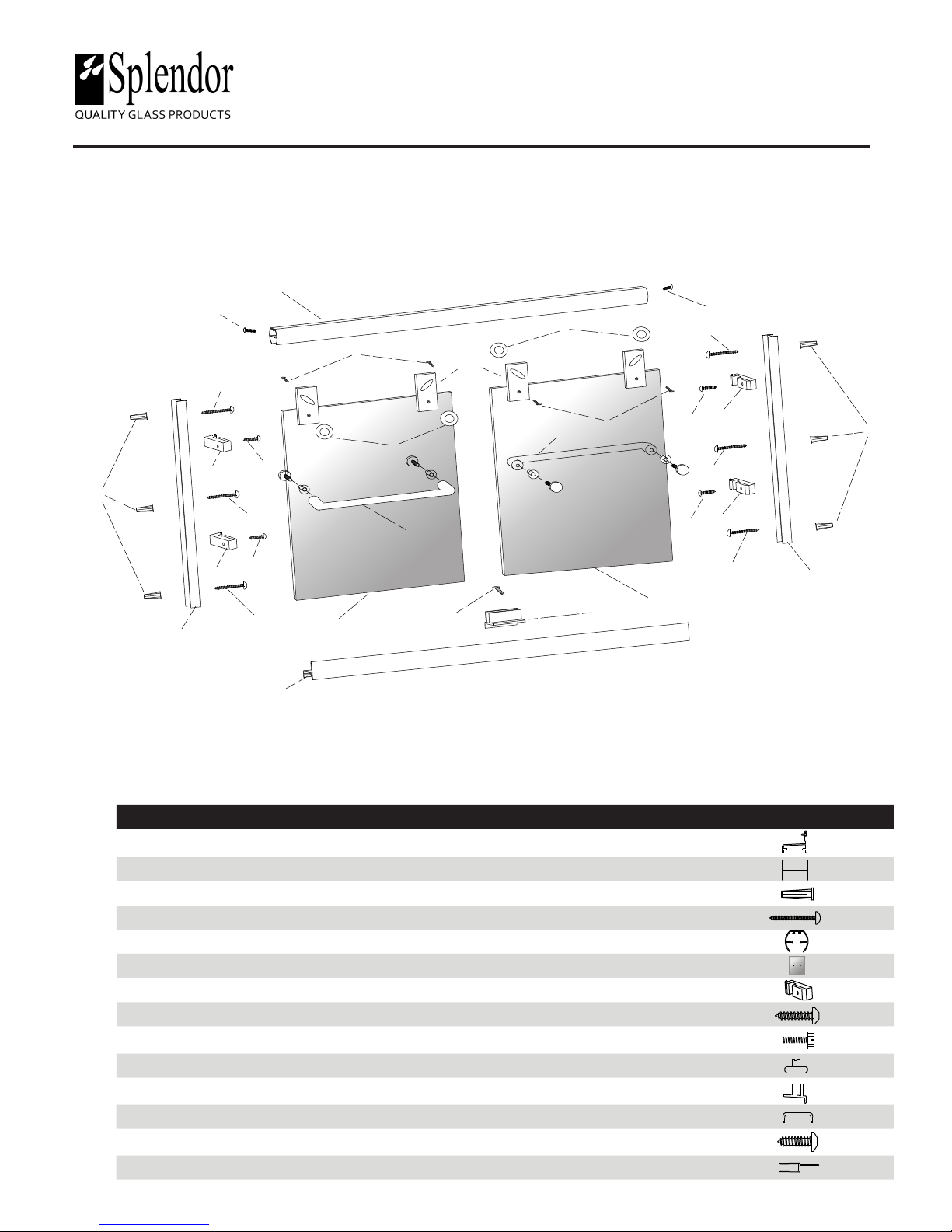
Parts
ITEM PART # QTY DESCRIPTION
A 882 1 Tub Track with T- Fin
B 884 2 Wall Jamb
C 113 6 Plastic Wall Anchor
D 110 6 #8 x 1 1/2” Pan Head Screw
E 880 1 Tub Header
F 2 Glass Panels
G 185 4 Vinyl Jamb Bumpers
H 115 4 #6 x 3/4” Pan Head Screws
I 116 4 #6 x 32-3/8” Hex Head Screws
J 132 4 Roller Bearing
K 153 1 Bottom Guide
L ETB 2 Towel Bar
L
I
F
K
G
H
D
G
H
D
B
C
M 119 3 #6 X 1/2” Pan Head Screws
N 886 4 Hanger Bracket - Attached
Page 1
REV-08/2017
Page 2

Tools
Hacksaw Philips Screwdriver Level #32 and 3/16” Drill Bit
Masking Tape
Safety Glasses
Tape Measure
Silicone
Installation Notes
.
Unpack your unit carefully. Lay out and identify all parts using the instruction sheets as a
reference. Before discarding the carton, check for any small hardware bags.
.
If any parts are damaged or missing, refer to the description noted in the instructions when
contacting your dealer for replacements.
.
Please wear safety glasses whenever drilling or cutting.
Drill
Mallet
.
Handle the glazed panels carefully; tempered glass is dicult to break, but the sharp corners
of the panels can damage tile and oor coverings.
.
Before installing, check the tub rim for level and both walls for plumb. If either are out of
plumb more than 3/8”, you may want to contact your dealer for tapered llers which can be
used to level tub track or plum the side jambs.
Caution: Tempered glass cannot be cut or drilled
Page 2
REV-08/2017
Page 3
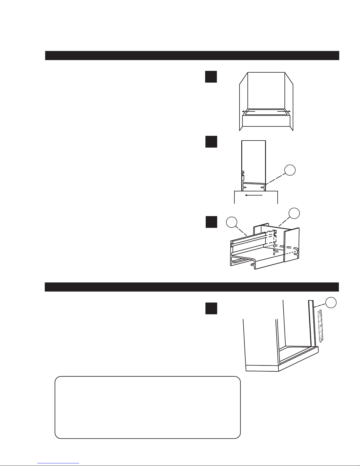
1.
SETTING the TUB TRACK with VINYL
Step 1a.
.
Measure from wall-to-wall, 1/2” above the sill and
cut the tub track (A) 1/16” short of these dimensions.
Step 1b.
.
Position the tub track in the center of the tub rim with
the tall leg facing the exterior. It may be necessary to le a
radius on the ends of the tub track and wall jambs to match
the corners of the tub.
Step 1c.
.
Press both wall jambs (B) into position over the tub track.
Masking tape can be used to temporarily hold parts in place.
1a
1b
1c
Measure
A
Exterior
B
A
2.
MARKING for WALL JAMB
Step 2a.
.
Use a level to plumb both wall jambs (B), then mark the
pre-drilled hole locations on the wall. You can use a center punch
or pencil.
.
Lightly mark along both sides of the tub track (A) with a pencil.
Remove all parts and drill the walls using a 3/16” drill bit (for tile or
marble use 3/16” masonry bit). Insert wall anchors (C) into holes.
Note: Attachments to berglass or acrylic can be made in two ways:
if reinforcement is built into the wall of the unit, drill six 1/8” diameter
holes and install the screws directly into the reinforcement.
If wall is not reinforced, drill 3/16” holes and install
plastic wall anchors (C).
B
2a
Page 3
REV-08/2017
Page 4
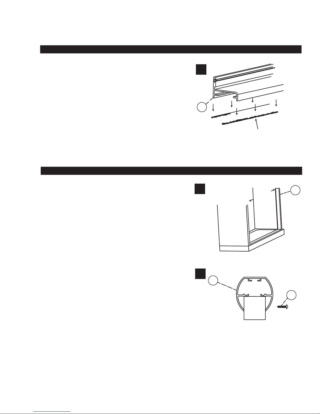
3.
SECURING the TUB TRACK
Step 3a.
.
Before replacing tub track (A), force a slight downward
bow in the middle of extrusion. This will ensure that the track
ts tight to the tub.
.
Run two beads of silicone inside the penciled mark on the tub rim.
Place the stay clean sill in the exact position you marked in step 2a
and set it rmly in the silicone.
.
Silicone the end where stay clean sill (A) meets the wall.
.
Replace wall jamb (B) and attach to wall with #8 X 1 1/2” screws (D).
Do not over tighten jamb screws.
4.
FITTING the TUB HEADER
Step 4a.
.
Measure from wall-to-wall at top of the wall jambs, subtract 1/16”
from this dimension and cut the tub header (E) to its nished
length. Set the header in place over the top of the wall jambs (B).
3a
4a
A
Place silicone along previously
pencil marked tub rim
B
Measure
- 1/16”
Step 4b.
.
From the inside of the enclosure, drill one hole (#32 drill bit )
through the header and the wall jamb on each end of the header.
.
Attach the header to the tub jamb using two #6 X 1/2” screws (M).
Page 4
4b
E
M
REV-08/2017
Page 5
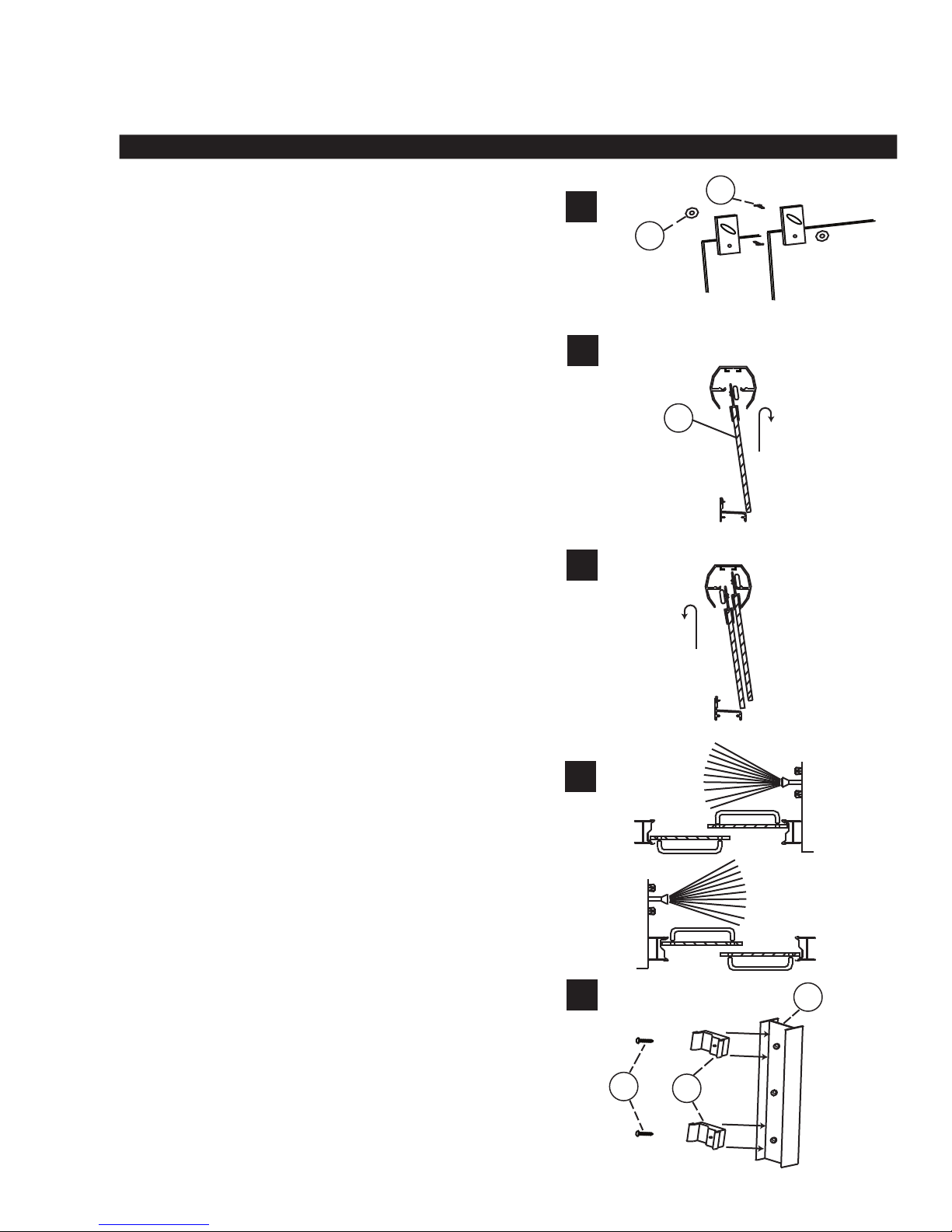
5.
INSTALL the GLASS PANELS
Step 5a.
.
To install panels, attach the four nylon roller bearings (J) to
the door panels using four #6-32 X 3/8” hex head screws (I)
centered in the slots in the top ns. Patterned glass is always
installed with the rough surface of the glass to the exterior of
the unit.
Step 5b.
.
To set slider glass in place, hold interior panel inside of
tub, insert rollers up into header and lower into roller track.
Step 5c.
.
Next, insert lower end of exterior slider panel in front of interior
slider panel by pushing lower ends far enough in to allow
clearance on inside edge of tub. Avoid roller-to-roller contact while
lifting panel into place.
5a
5b
5c
J
Rough Exterior
Outside
F
Outside
I
Rough Exterior
Inside
Inside
.
The inside slider panel will close against wall jamb on showerhead side.
Step 5d.
.
The interior panel should always be positioned closest to the
showerhead for maximum waterproong, as shown in illustration.
Step 5e.
.
Next, push vinyl jamb bumpers (G) into side jambs (B)
approximately 1” below top screw and bottom screw.
.
Align the slot in the bumper with the outer rail of the slider panel
and mark holes through the bumper and drill with #32 drill bit.
5d
5e
B
H
G
.
Screw bumper in with #6 X 3/4” pan head screw (H). Repeat on
other side. Do not over tighten or rubber can tear rubber with movement.
Page 5
REV-08/2017
Page 6
5.
INSTALL the GLASS PANELS CONTINUED
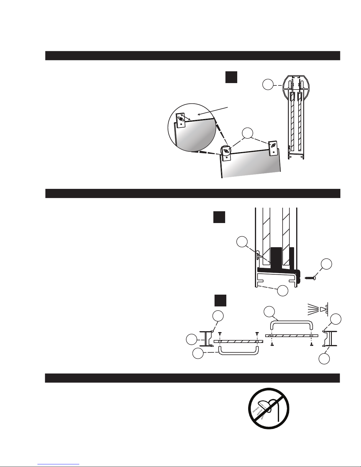
Step 5f.
.
If the door panels are not parallel to their respective wall jambs,
remove and adjust rollers up or down in their slots to compensate
for out of plumb walls.
6.
CENTER GUIDE
Step 6a.
.
Locate the nylon bottom guide (K) in the center of the
tub track (A) and place the center guide into place.
.
Using the factory holes as a template, drill through hole into
track with # 32 drill bit.
5f
E
Adjust roller in slot
Interior
J
6a
K
.
Attach center guide with #6 X 1/2” pan head screw (M).
Step 6b.
.
Units include two Euro towel bars. These should be enclosed
in a sealed box with all components attached. If back of knob
hits when rolling enclosure, take clear plastic spacers o.
Install on glass using the diagram below as reference.
7.
SILICONE SETUP
Step 7a.
.
Silicone the entire unit where metal meets wall and curb.
We recommend you let silicone set for 24 hours before
using shower
M
A
6b
G
B
L
L
G
B
24hrs
Page 6
REV-08/2017
 Loading...