

SPL Dynamics MD-600.1, MD-1500.1, MD-60.4, MD-200.4, MD-400.2 Operating Instructions Manual
SPL DYNAMICS MD-series amplifiers provide high performance sound reinforcement
for your car audio equipment. Its versatility enables compatibility with optional
Equalizers, Active Crossovers and Digital Signal Processors in a customized system.
Its built-in very wide range bandpass crossovers allow you to make all the cut-offs of
a full active system with amplifier’s filters.
MD - series
www.spldynamics.fi
Class D Amplifier
To achieve optimum performance, it is highly recommended that you read this
Owners Manual before beginning installation. Check also our webpages to have
more information about different system configurations.
OPERATING INSTRUCTIONS
BEFORE OPERATING THE UNITS, PLEASE READ THIS MANUAL
THROUGHLY AND RETAIN IT FOR FUTURE REFERENCE
R
R
MD-60.4
MD-200.4
MD-400.2
MD-600.1
MD-1500.1
INTRODUCTION
FERTURES
WARNING
2
• Variable LPF : 50Hz - 4KHz
• Variable HPF : 15Hz - 600Hz (x1),150Hz - 6KHz (x10)
• Frequency Multiplier Switch Control
• Bandpass Filters: LPF & HPF can be used at the same time
• Soft-On / Turn-Off Circuit
• Overheat and Short Circuit Protection
• MOS-FET Pulse Modulated Power Supply
• Automotive Style Protection Fuses
• Upright Easy Access Speaker and Power Terminals
• Power ON and Protection LED Indicator
2/4 Channel
• Variable LPF : 40Hz - 180Hz
• Variable Subsonic 17 - 50Hz
• Variable Bass Freq 30 - 80Hz
• Variable Phase Control 0-180 degrees
• Bass Boost Centered 0dB 6dB 12dB
• Remote Level Control
• Soft-On / Turn-Off Circuit
• Overheat and Short Circuit Protection
• MOS-FET Pulse Modulated Power Supply
• Upright Easy Access Speaker and Power Terminals
• Power ON and Protection LED Indicator
Mono
High powered audio systems in a vehicle are capable of generating “Live Concert”
high levels of sound pressure. Continued exposure to excessively high volume sound
levels may cause hearing loss or damage. Also, operation of a motor vehicle while
listening to audio equipment at high volume levels may impair your ability to hear
external sounds such as; horns, warning signals, or emergency vehicles, thus
constituting to a potential traffic hazard. In the interest of safety, Consumer
Electronics recommends listening at lower volume levels while driving.

WIRING CO NNE CTIONS
a. Select a suitable location that is convenient for mounting. is
accessible for wiring,and has ample room for air circulation
and cooling.
b. Use the amplifier as a template to mark the mounting holes.
Remove the Amplifier and drill 4 holes. USE EXTREME CAUTION,
INSPECT UNDERNEATH SURFACE BEFORE DRILLING.
c. Secure the Amplifier using the screws provided.
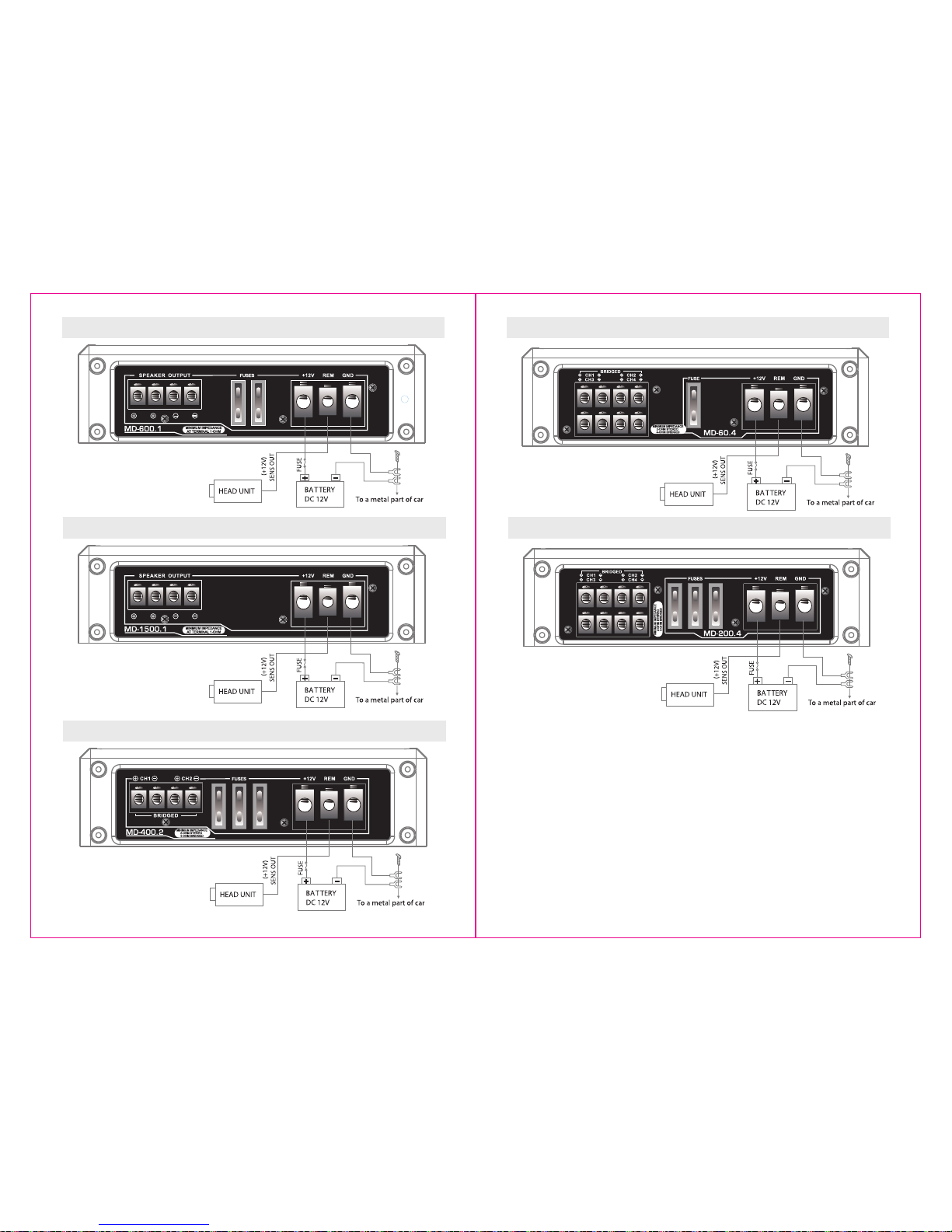
A. CONNECTING THE POWER (Fig. 1)
CAUTION :
AS A PRECAUTION, IT IS ADVISABLE TO DISCONNECT THE VEHICLE’S BATTERY
BEFORE MAKING CONNECTION TO THE +12 VOLT SUPPLY WIRING.
50/33/20 mm2 depending from the model( Thicker if planning for additional
Amplifiers) wire is recommended for both the power and ground wires. 12 Gauge,
for the remote turn-on wire. Both types are available at most Mobile Audio Dealers
or Installation Shops.
(1) GROUND: To Vehicle Chassis
To avoid unwanted ignition noise caused by ground loops, it is essential that the
Amplifier be grounded to a clean, bare, metal surface of the vehicle’s chassis.
NOTE:
GROUND WIRE SHOULD NOT BE EXTENDED MORE THAN 3 FT. (1 METER).
(2) +12 Volt(Fused) Constant Power: To Battery (+)
Due to the power requirements of the Amplifier, this connection should be made
directly to the positive (+) terminal of battery. For safety measures, install an in-line
Fuse Holder (not included) as close to the battery positive (+) terminal as possible
with an ampere rating; not to exceed total value of fuses in Amp.
(3) Remote Turn-On Input: To Power Antenna output of Car Stereo This Amplifier is
turned “ON” remotely when the vehicle’s stereo is turned “ON”.
NOTE :
If your radio does not have a +12 Volt output lead when the radio is turned ON, the
“RMT” terminal on the Amplifier can be connected to vehicle’s accessory circuit that
is live when the key is “ON”.
MD - 60.4 : 40A x 1 MD - 200.4 : 35A x 3 MD - 400.2 : 35A x 3
MD -600.1 : 30A x 2 MD -1500.1 : NO
3 4
PLANNING YOUR SYSTEM
MOUNTING YOUR AMPLIFIER
Before beginning the installation, consider the following:
a. If you plan to expand your system by adding other components sometime in the
future, ensure adequate space is left, and cooling requirements are met.
b. There has to be pre-amp outputs on your headunit.
SPL Dynamics Class D amplifiers has been designed to accept only Low-Level
signal source. So there has to be pre-amp outputs on your headunit.
c. Are your components matched? The RMS power rating of your speakers must be
equal or greater than the amplifier’s. They also must be 1 - 8 Ohms impedance.
(This information is normally printed on the speaker magnet).
d. Consider both the length of your leads, and routing when determining the
mounting location. Pre-Amp Input Jacks require a length of high quality
shielded male to male RCA patch cord.
The mounting position of your Amplifier will have a great effect on its ability to
dissipate the heat generated during normal operation. It has an ample heat sink for
heat dissipation, and also designed with a thermal shut-down(for heat protection)
circuit, making it reasonably tolerant of mounting variations. Any configuration which
allows moving air to be directed over the cooling fins will improve heat dissipation
dramatically. DO NOT enclose the amplifier in a small box or cover it so that air
cannot flow around fins.
Temperatures in car trunks have been measured as high as 175 F(79.5 C) in the
summer time. Since the thermal shut-down point for the Amplifier is 185 F(85 C), it
is easy to see that it must be mounted for maximum cooling capability. To achieve
maximum advantage of convection air flow in an enclosed trunk, mount the amplifier
in a vertical position, on a vertical surface.
Cooling requirements are considerably relaxed when mounting inside the passenger
compartment since the driver will not
often allow temperatures to reach a critical
point. Floor mounting under the seat is usually satisfactory as long as there is at
least 1 inch(2cm) above the Amplifier’s fins for ventilation.
NOTE :
Use always low-level input if there is pre-amp outputs in your headunit.
Distortion level is considerably lower from pre-amp(Low Level) outputs.
Model : MD - 400.2
B. VARIABLE “LPF” LOW-PASS FILTER
MONO (40Hz-180Hz):
Low-Pass filter circuitry of SPL Dynamics Class D Amplifiers is always activated
because these models are designed only to subwoofer use. Low-Pass filter
allows frequencies below (40-180Hz) to be amplified.
2/4CH (50Hz-4KHz):
“12/24dB” activates the Low-Pass filter circuitry, thus allowing frequencies
below (50Hz-4KHz) to be amplified. You can use this filter as :
• Subwoofer Low-Pass filter
• Full-Active system’s Midbass Low-Pass filter
• Full-Active system’s Midrange Low-Pass filter
For normal full-range frequency speaker configuration, as component system with
passive crossover or coaxial speakers, set to “OFF”.
5 6
Model : MD-600.1
Model : MD - 1500.1
Fig. 1
Fig. 1
Model : MD-60.4
Model : MD - 200.4
Fig. 1
Fig. 1
Fig. 1
 Loading...