

Page 1

OWNERS MANUAL
Page 2
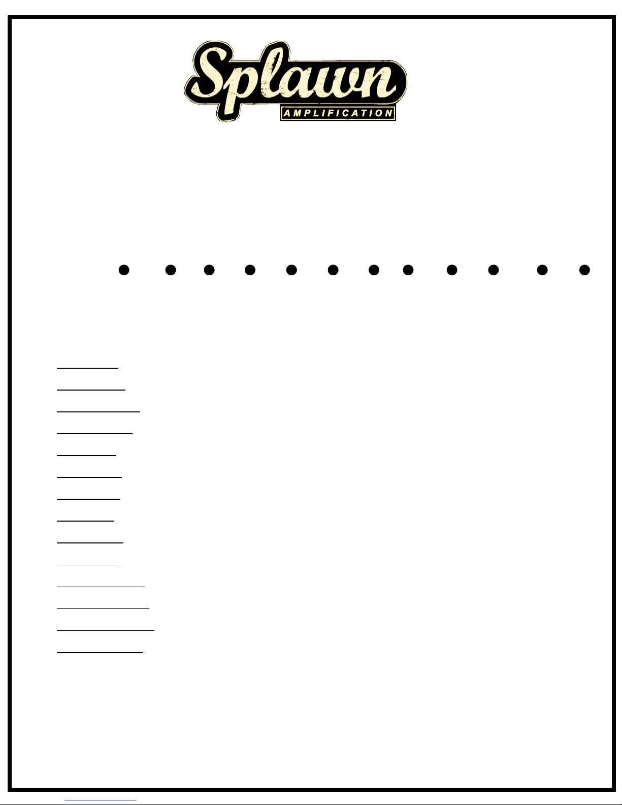
POWERONSTANDBYONRESONANCE
PRESENCE
BASS
MIDDLE
TREBLE
SOLO
by
Splawn
VOLUME
GAIN
VOLUME
TREBLE
BASS
_____________CLEAN CHANNEL_______________
_______________________________________OVERDRIVE CHANNEL_______________________________
GAIN
N
Thank you for purchasing your new Splawn amplifier. We have put together a little information that will help you
understand the amp and all of its functions. All of our amps are built in our shop in Dallas NC right here in the USA. We
build all of our speaker cabs and head boxes in house. Some parts of the amplifier are out sourced such as the
chassis's, circuit boards and transformers. The transformers are custom wound by Heyboer and are also made in the
USA. We hope that this amplifier will give you years of tonal pleasure.
Nitro Front Panel Controls
1. Power Switch
-Switches main AC power on or off
2. Standby Switch
4. Presence Control
5. Bass Control
6. Middle Control
7. Treble Control
8. Solo Volume
9. Master Volume
10. Gain Control
11. Clean Bass Control
12. Clean Treble Control
13. Clean Volume Control
14. Clean Gain Control
-Switches the high voltage on or off
-High frequency control on the output section
-Controls the bass frequency on the overdrive channel
-Controls the middle frequency on the overdrive channel
-Controls the treble frequency on the overdrive channel
-Switchable volume control on the overdrive channel activated by the footswitch
-Controls the overall volume of the overdrive channel
-Controls the amout of pre-amp gain to the overdrive channel
-Controls the bass frequency on the clean channel
-Controls the treble frequency on the clean channel
-Controls the overall volume of the clean channel
-Controls the amount of pre-amp gain to the clean channel
Splawn Amplification
115 South Gaston St.
Dallas, NC 28034
704-922-0020
www.splawnguitars.com
3. Resonance Control
-Low frequency control on the output section
ITRO
Page 3
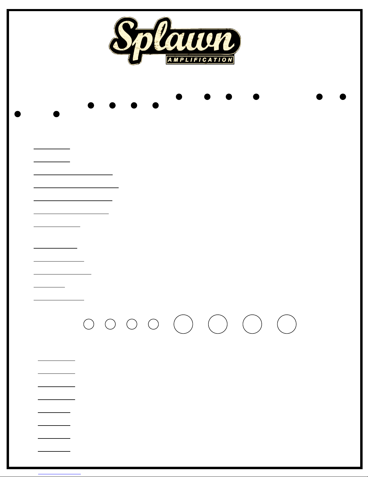
Nitro Rear Panel Controls
1. Footswitch A
-TRS 1/4" Jack Tip switches Solo Volume-- Ring switches OD1/OD2
2. Footswitch B
3.Series Effects Loop Level Switch
4. Series Effects Loop Bypass Switch
5. Series Effects Loop Return Jack
6. Series Effects Loop Send Jack
7. Half Power Switch
8. Speaker Outputs
9. Impedence Selector
10. Main Voltage Selector
11. Main Fuse
12. High Tension Fuse
-TRS 1/4" Jack Tip switches Clean/Overdrive
-+4db -10db switch for matching line levels to effects units
-True bypass switch
-Connection from the output of the effects device
-Connection to the input of the effects device
-Disconnects the outside power tubes
-Connection to the speaker cabinet (never run a tube amp without a speaker)
-4/8/16 ohm selector to match the load of the speaker cabinet
-100/120/220/240 voltage selector to match the input voltage
-Use 4 amp 250 volt fuse for 100 or 120 volt setting Use 2 amp 250 volt fuse for 220/240 volt setting
-Use 1 amp 250 volt Slow Blow Fuse
FOOTSWITCH
A B
LEVEL
BYPASS
RETURN
SEND
OUT/+4 db
OUT/BYPASS
IN/-10 db
IN/ACTIVE
EFFECTS LOOP
SPEAKERS
4
8
16
OUTPUT
SELECTOR
VOLTAGE
MAINS INPUT
MAINS FUSE
4A 120V
HT FUSE
1A Slow-Blow
100 WATT RMS
HALF POWER
FULL POWER
by
Splawn
2A 220/240V
100v-120v
220v-240v
N
always set the amps impedence to half of the speaker cabs impedence when using half power
1 2 3 4
5 6 7 8
1. Pre-amp tube
- 12AX7 2nd gain stage of the clean channel
2. Pre-amp tube
3. Pre-amp tube
4. Pre-amp tube
5. Power Tube
6. Power Tube
7. Power Tube
-12AX7 Side A 1st gain stage for clean & OD channels -- Side B 2nd gain stage of OD channel
-12AX7 Side A 3rd gain stage of OD channel -- Side B 4th gain stage of OD channel
-12AX7 Phase Inverter
- EL34/KT77 -- KT88/6550
- EL34/KT77 -- KT88/6550
- EL34/KT77 -- KT88/6550
8. Power Tube
- EL34/KT77 -- KT88/6550
Tube Layout
ITRO
Page 4
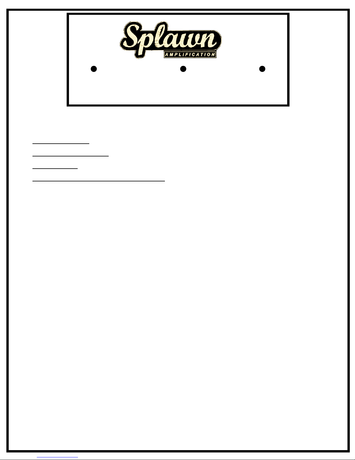
Nitro Footswitch Operation
1. Clean/Overdrive Switch
- LED on indicates OD Channel -- LED off indicates Clean Channel
2. Overdrive 1 / Overdrive 2 Switch
3. Solo Boost Switch
- LED on indicates OD2 gain boost -- LED off indicates OD1
- LED on indicates Solo Volume control activated
Overdrive 1/ Overdrive 2
Clean/Overdrive
Solo Boost
Footswitch connections -- Two 1/4" TRS plugs on a 25' cable
Setting up the Amplifier:
After unpacking your new amp, Turn the amp around so the back faces you. Remove the four screws to
remove the back cover of the amp. You will find the tubes packaged tightly on the left side of the Amp.
Carefully remove the package and remove the tubes. You will have three preamp tubes and four power
section tubes.
Power Section Tubes:
Un-box the Power section tubes. Keep the boxes!! They are marked with tube ratings! You will see on the
base of the tube there is a “key” guide to align the tube into the socket. Starting with the tube socket on the
far right, Line up the key with the slot in the socket, From the top of the tube, firmly press
the tube into the socket until the base of the tube is flush with the Socket. Insert these tubes into the tube
sockets. The tubes are matched so you may install them in no particular order. After you install a tube
carefully hold the tube spring retainer and stretch it over the top of the tube and center it. These are light
metal and can bend. If you happen to bend them you can shape it to the tube while its installed. Reinstall
the rear cover and get ready to fire this monster amplifier to life!
WARNING:
Please Check the Voltage selector on the back for proper Voltage selection! Please check the volume
control levels on all channels before powering on. After you plug in the amplifier, Flip the power switch
down to turn on. Wait for a minute for the tubes to warm, then turn on the Standby switch. The Amp is ready
for explosive guitar sounds!
This Amplifier will get VERY loud. Remember you only have one set of ears!
Limited Lifetime Warranty.
New Amplifiers are lifetime warranted to the original purchaser
against failure of materials and workmanship. No other warranty applies. Tubes, transformers and speakers are
warranted for a period of ninety days. This warranty applies only if the amplifier has not been damaged by
accident, misuse or as a result of repair or modification. Splawn reserves the right to make any design changes
without notice or obligation to incorporate these changes in products previously purchased.
All warranty repairs are to be done by Splawn Amplification.
Splawn Amplification
115 South Gaston St.
Dallas, NC 28034
Dimensions
29” Wide, 11.5” Tall, 8.5” Deep, 50lbs
 Loading...