

Page 1

Manual
Transpressor
Model 1080
Dynamic Processor
Page 2
Manual Transpressor, Model 1080
Version 1.0 – 7/2010
Developer: Jens Gronwald
This manual contains a description of the product. It in no way represents a guarantee of
particular characteristics or results of use. The information in this document has been carefully compiled and verified and, unless otherwise stated or agreed upon, correctly describes
the product at the time of packaging with this document.
Sound Performance Lab (SPL) continuously strives to improve its products and reser ves the
right to modify the product described in this manual at any time without prior notice. This
document is the property of SPL and may not be copied or reproduced in any manner, in part
or fully, without prior authorization by SPL.
SPL electronics GmbH
Sohlweg 80, 41372 Niederkruechten, Germany
Phone +49 (0)2163 983 40
Fax +49 (0)2163 983 420
E-Mail: info@spl.info
Internet: www.spl.info
The construction of the Transpressor, Model 1080, is in compliance with the
standards and regulations of the European Community.
Notes on Environmental Protection
At the end of its operating life, this product must not be disposed of with regular
household waste but must be returned to a collection point for the recycling of
electrical and electronic equipment. The wheelie bin symbol on the product,
user‘s manual and packaging indicates that. The materials can be re-used in
accordance with their markings. Through re-use, recycling of raw materials, or
other forms of recycling of old products, you are making an important contribution to the
protection of our environment. Your local administrative office can advise you of the responsible waste disposal point.
WEEE Registration: 973 349 88
© 2010 SPL electronics GmbH. All rights reserved. Names of other companies and their
products are trademarks of their respective owners.
2
Transpressor
Page 3

Symbols and Notes 4
Scope Of Delivery and Packaging 4
Important Security Information 4
Hook Up 5
Introduction 6
Dual Dynamic Processing 6
Use, Applications, Special Technical Features 7
Rear Panel 8
Signal Connections, Input and Output Electronics, 1/4" Jacks, XLR sockets 9
Power connection and fuse, Voltage Selector 9
Power Switch, GND Lif t 9
Balanced connections, Unbalanced connections 10
Input, Sidechain, Stereo Link/Slave, Output 1 & Output 2 11
Content
Operation 12
Overview 12
Control Elements 13
The Transient Designer, TD On, Attack, Sustain 13
The Twin Core Compressor, Threshold, Ratio, Attack 14
ATTACK AUTO mode, Release, RELEASE AUTO mode, Make Up 15
Detector/EXT SC, OFF, FILTER; Detector/1, 2, 3; GR meter, OUT meter 16
ON, SIG 17
Parallel Mix 17
TD On, Comp On 17
Comp Pre, Link Slave 18
Using the Transient Designer 19
Drums & Percussions, Drums: Ambience 19
Guitars, The Transfer Of Dynamic Structures, Bass, The Re-Invention Of Reverb 20
Backings, Keyboards & Sampler, Post Production, Mastering 21
Specifications 22
Block Diagram 23
Copy Master Recall Settings 24
Your Notes 25
Transpressor
3
Page 4
Symbols and Notes
N THIS MANUAL A LIGHTNING SYMBOL WITHIN A TRIANGLE WARNS YOU ABOUT THE
POTENTIAL FOR DANGEROUS ELECTRICAL SHOCKS – WHICH CAN ALSO OCCUR EVEN AFTER
THE MACHINE HAS BEEN DISCONNEC TED FROM A POWER SOURCE.
AN EXCLAMATION MARK (!) WITHIN A TRIANGLE IS INTENDED TO MAKE YOU AWARE OF
IMPORTANT OPERATIONAL ADVICE AND/OR WARNINGS THAT MUST BE FOLLOWED. BE
ESPECIALLY ATTENTIVE TO THESE AND ALWAYS FOLLOW THE ADVICE THEY GIVE.
The symbol of a lamp directs your attention to explanations of important functions or applications.
Attention: Do not attempt any alterations to this machine without the approval or supervision
of SPL electronics GmbH. Doing so could nullify completely any and all of your warranty/guarantee rights and claims to user support.
Scope Of Delivery and Packaging
The scope of delivery comprises the Frontliner, the external power supply, the guarantee card
and this manual.
Please keep the original packaging. In case of a service procedure the original packaging
ensures a safe transport. It also serves as a safe packaging for your own transports if you do
not use special transportation cases.
Important Security Information
Please note and retain this manual. Carefully read and follow all of the safety and operating
instructions before you use the machine. Be doubly careful to follow all warnings and special
safety instructions noted in this manual and on the unit.
Connections: Only use the connections as described. Other connections can lead to health
risks and equipment damage.
Water and humidity: Do not use this machine anywhere near water (for example near a wash
basin or bath, in a damp cellar, near swimming pools, or the like). In such cases there is an
extremely high risk of fatal electrical shocks!
Insertion of foreign objects or fluids: Never allow a foreign object through any of the
machine‘s chassis openings. You can easily come into contact with dangerous voltage or
cause a damaging short circuit. Never allow any fluids to be spilled or sprayed on the machine.
Such actions can lead to dangerous electrical shocks or fire!
Opening the unit: Do not open the machine housing, as there is great risk you will damage the
machine, or – even af ter being disconnected – you may receive a dangerous electrical shock!
Electrical power: Run this machine only from power sources which can provide proper power
in the range from 100 to 250 volts. When in doubt about a source, contact your dealer or a
professional electrician. To be sure you have isolated the machine, do so by disconnecting all
power and signal connections. Be sure that the power supply plug is always accessible. When
not using the machine for a longer period, make sure to unplug it from your wall power socket
and from the guitar amp.
Cord protection: Make sure that your power and guitar amplifier signal cords are arranged
to avoid being stepped on or any kind of crimping and damage related to such event. Do not
allow any equipment or furniture to crimp the cords.
Power connection overloads: Avoid any kind of overload in connections to wall sockets,
extension or splitter power cords, or to signal inputs. Always keep manufacturer warnings
and instructions in mind. Overloads create fire hazards and risk of dangerous shocks! >
4
Transpressor
Page 5
Lightning: Before thunderstorms or other severe weather, disconnect the machine from wall
power (but to avoid life threatening lightning strikes, not during a storm). Similarly, before
any severe weather, disconnect all the power connections of other machines and antenna and
phone/network cables which may be interconnected so that no lightning damage or overload
results from such secondary connections.
Air circulation: Chassis openings offer ventilation and serve to protect the machine from overheating. Never cover or otherwise close off these openings. Never place the machine on a soft
surface (carpet, sofa, etc.). Make sure to provide for a mounting space of 4-5 cm/2 inches to
the sides and top of the unit when mounting the unit in racks or on cabinets.
Controls and switches: Operate the controls and switches only as described in the manual.
Incorrect adjustments outside safe parameters can lead to damage and unnecessary repair
costs. Never use the switches or level controls to effect excessive or extreme changes.
Repairs: Unplug the unit from all power and signal connections and immediately
contact a qualified technician when you think repairs are needed – or when moisture or foreign objects may accidentally have gotten in to the housing, or in cases
when the machine may have fallen and shows any sign of having been damaged.
This also applies to any situation in which the unit has not been subjected to any
of these unusual circumstances but still is not functioning normally or its performance is substantially altered.
In cases of damage to the power supply and cord, first consider turning off the main circuit
breaker before unplugging the power cord.
Important Security Information
Replacement/substitute parts: Be sure that any service technician uses original replacement
parts or those with identical specifications as the originals. Incorrectly substituted parts can
lead to fire, electrical shock, or other dangers, including further equipment damage.
Safety inspection: Be sure always to ask a service technician to conduct a thorough safety
check and ensure that the state of the repaired machine is in all respects up to factory standards.
Cleaning: In cleaning, do not use any solvents, as these can damage the chassis finish. Use
a clean, dry cloth (if necessary, with an acid-free cleaning oil). Disconnect the machine from
your power source before cleaning.
Be very careful to check that the rear chassis power selection switch is set to the correct
local line voltage position before using the unit (230 V position: 220-240 V/50 Hz, 115 V position: 110-120 V/60 Hz)! When in doubt about a source, contact your dealer or a professional
electrician.
Before connecting any equipment make sure that any machine to be connected is turned off.
Follow all safety instructions on pages 4 and 5 and read further information on connections
on pages 7-10.
Place the unit on a level and stable surface. The unit’s enclosure is EMC-safe and effectively
shielded against HF interference. Nonetheless, you should carefully consider where you place
the unit to avoid electrical disturbances. It should be positioned so that you can easily reach
it, but there are other considerations. Try not to place it near heat sources or in direct sunlight,
and avoid exposure to vibrations, dust, heat, cold or moisture. It should also be kept away
from transformers, motors, power amplifiers and digital processors. Always ensure sufficient
air circulation by keeping a distance of 4-5 cm/2 inches to the sides and top of the unit.
Hook Up
Transpressor
5
Page 6

Introduction
Dual Dynamic Processing
In the late 1990’s SPL revolutionized audio dynamic processing with a groundbreaking new
technology. The Transient Designer made it possible, for the first time, to act on the signal in
order to amplify or attenuate its transient and to extend or shorten its decay, without affecting
the signal level. Thus, dynamic processing that used to be linked to a given threshold became
a more powerful sound-shaping tool focused exclusively on the signal’s attack.
Common compressors/limiters are level dependent. If we were to imagine a dynamically
ideal signal curve, the attack and decay of the curve would describe a bell. A compressor/
limiter acts from a predefined threshold. Once the threshold is met, the waveform is modified
by a preset gain control curve defined by several parameters. Thus, if the signal level is too
high you can limit it to avoid overdriving the electronics. You can process individual signals
separately in order to make them sit better in a mix, modif ying only their level and not their
sound, or intentionally changing the sound of the signal with the compressor (to make a bass
drum sound more incisive, for example). In complex signals, peaks can be limited so that the
average level is increased as a whole. It is not our intention to describe all possible applications of a compressor, but rather to sustain that its processing is directly linked to a threshold.
The Transient Designer, on the other hand, focuses on the form of the signal curve instead
of taking the signal level as reference. It starts processing a signal as soon as it detects an
impulse. Therefore, it does not matter how loud the signal is because it will be processed
equally by the Transient Designer.
A transient can be defined as the first dynamic impulse of a waveform. These transient
elements appear before the sound has completed a full cycle and they are decisive for sound
recognition. It is not that important whether a snare is played loudly or softly, we can nevertheless recognize its sound. Changes in the transient structure have a major impact on the
sound character — which makes the Transient Designer an essential dynamic tool for sound
shaping. If you wanted to process these parts of the signal with a compressor, the attack time
would have to be so fast that it would be inappropriate for the rest of the signal, resulting
in unwanted side effects, like pumping. The Transient Designer acts precisely where a traditional compressor cannot, making it the best complement for dynamic processing.
The Transpressor combines both dynamic processing technologies in one single unit. The mix
of this already powerful processing tools results in much more than the sum of their individual
capabilities. At the same time, the possibility of changing the order of the processing modules
opens up new approaches to create totally new effects: the compressor responds differently
when the transient structure is modified before reaching the compression stage; while an
already compressed signal can retain its character — or have it improved — when processed
with the Transient Designer.
The Transpressor makes patent the benef its of being able to work freely at both stages of
the dynamic process. In the studio — and also live — you must often process the transients
of percussive signals (snare, bass drum...) and then make the sound more compact through
compression. This entails the need to put together different processing units specifically for
this task — a job that the Transpressor can accomplish singlehandedly. If it were necessary
to achieve a constant level through compression and only then shape the transient structure,
the Transpressor allows you to easily change the processing order with one single button.
This applies not only to percussive instruments, but also to all other critical and demanding
dynamic signals (specially electric bass and guitar): the Transpressor is an incredibly versatile
and multifunctional dynamic processing tool.
6
Transpressor
Page 7
Use
• Live and in the studio as an ultraversatile and multifunctional one-channel dynamic
processing tool.
• Link function for stereo processing with two units.
Applications
• Comprehensive corrective and creative dynamic processing for all sorts of instruments
and vocals.
• The use of both modules is specially suited for processing dynamic signals like percussion instruments, bass, guitar, piano, etc.
• As a Transient Designer
• As a compressor
Special Technical Features
• One of the Transpressor’s most characteristic features is the Double VCA circuitry used in
the compressor and, for the first time, also in the Transient Designer. A differential stage
reduces side effects (clicks and plops) and the half load per VCA dramatically reduces
THD.
Introduction
• The operational amplifiers for the compressor circuitry have very low DC offsets and
meet high-precision measurement standards. Therefore, control voltages are extremely
precise — a prerequisite for high-quality signal processing.
• High-grade Bur r-Brown operational amplif iers in the input and output stages.
• Central star grounding minimizes interferences and other negative ef fects that could
affect the ground paths. This leads to a ”cleaner” — in the truest sense of the word —
sound quality..
Transpressor
7
Page 8
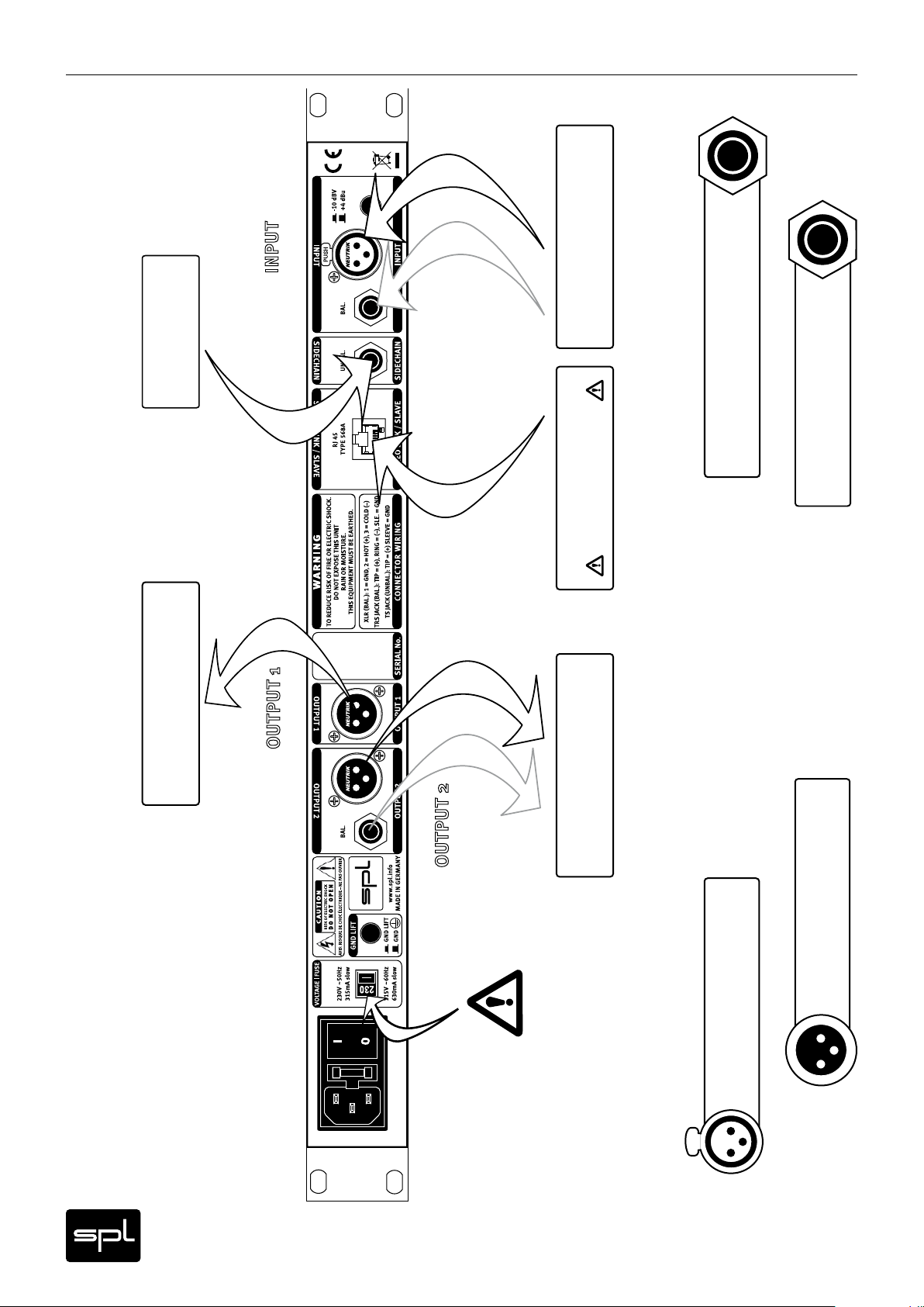
Rear Panel
Equalizer
DAW Insert Sends
Preamp, Console or
Wiring Diagram
Pin wiring TRS (stereo jack) sockets:
Tip=hot (+), Ring=cold (-), Sleeve=GND
Tip=hot (+), Sleeve=GND
Pin wiring TS (mono jack) sockets:
Insert Returns
(Console, DAW, etc.)
NO ETHERNET
2nd Transpressor
other FX units ...
Further Insert Returns,
1=GND, 2=hot (+), 3=cold (-)
Pin wiring XLR output sockets:
Make sure that
reflects the correct
local power line voltage.
the voltage switch setting
8
Pin wiring XLR input sockets:
1=GND, 2=hot (+), 3=cold (-)
1
3
PUSH
2
Transpressor
21
3
Page 9

Connections & Switches
Signal Connections
Turn off the unit before connecting or disconnecting any cable or equipment to it. Otherwise
you risk the possibility of damaging your ears or equipment.
Input and Output Electronics
The input and output electronics of the Transpressor use bridge circuits that keep the signal
flow constant, reg ardless of malfunctioning equipment and power outages (Hard Bypass).
The bridge circuits rely on high-quality relays. Contact surfaces are gold-plated to provide
better conductivity, and encapsulated to avoid external influences due to climate or atmospheric conditions.
TRS and TS sockets (1/4" stereo and mono jacks)
The Jack sockets at INPUT and OUTPUT 2 are balanced TRS. Use stereo jack connectors only
to establish balanced connections. By using mono jacks you establish unbalanced connections. The SIDECHAIN input socket is unbalanced. You can use either stereo or mono jacks,
this wiring is always unbalanced.
XLR sockets
All signal connections are made via balanced XLR connectors. Inputs are always female and
accept male connectors; outputs are always male. All in all, a very comprehensible principle.
Rear Panel
Power connection and fuse
Connect the power cord to the rear MAINS INPUT socket. Transformer, power cord and case
connection conform to VDE, UL and CSA requirements.
The fuse is accessible from outside and placed right behind the flap right from the socket.
Fuse ratings are 315 mA slow blow (
230
volts) or 630 mA slow blow (
115
volts).
Voltage Selector
The rear panel VOLTAGE selector sets the local line voltage (115 V position: 110-120 volts/6o Hz,
230 V position: 220-240 volts/50 Hz). The diagram shows the correct switch position for 230 V
power supply.
BEFORE you connect electrical power make sure that the VOLTAGE selector setting reflects
the correct local power line voltage.
Power Switch
Use the POWER switch on the rear panel to turn the unit on or off. The blue ON LED above the
GR LED on the front panel will light up as soon as you switch the unit on, regardless of the
position of the TD ON and COMP ON push buttons.
GND Lift
The rear panel GND LIFT switch eliminates hum by separating the internal ground from the
unit’s housing ground. Hum can, for example, result when this unit’s housing has a common
ground connection with other devices that might have a different ground potential. The
switch is usually deactivated to retain the shielding of the housing.
VOLTAGE | FUSE
230V ~50Hz
315mA slow
115V ~60Hz
630mA slow
GND LIFT
GND LIFT
GND
I
0
I
0
Transpressor
9
Page 10

Rear Panel
Balanced and unbalanced connections
Balanced connections
It is impossible to exclude interferences when a single audio signal is transmitted. Shielding is
effective against electric, but not against electromagnetic influences. Motors, transformers,
and alternating current can always induce interferences. But even if the transmission would
succeed, differences in ground potentials between driver and receiver would produce disturbances.
In balanced connections a reference signal with reversed polarity is transmitted additionally
to the audio signal through a second wire. The ground signal is routed separately through
a third wire. Input and output stages are drivers and receivers, and the receiving stage can
suppress interferences by subtracting the difference between audio and reference signal.
Unbalanced connections
Unbalanced connections from and to RCA or 1/4“ TS sockets can be made without adaptors to
the balanced XLR sockets. The correct wiring is important. The diagram shows the pin configuration of the XLR sockets and how to correctly connect them for unbalanced connections:
balanced
2
1
3
Input
unbalanced
balanced
2
1
3
1
Output
2
3
unbalanced
1
2
3
1=GND
2=hot (+)
3=cold (-)
Connections to RCA sockets are always unbalanced, a wiring to jack connectors can be both
balanced (1/4" TRS/stereo jack) or unbalanced (1/4" TS/mono jack). We recommend to use
individually configured cables from XLR to RCA or jack sockets instead of adaptors. You can
get cables in any needed configuration from audio dealers. With the diagram above, the
dealer can ensure to provide the appropriate cable for your application.
10
Transpressor
Page 11

Inputs and Outputs
Input
The balanced XLR and 1/4" inputs serve to connect signal sources to the Transpressor.
The Line inputs’ maximum input level is +21 dBu.
The XLR and 1/4" inputs are connected in parallel, which means that they should not be used
simultaneously.
Use the “+4 dBu/-10 dBV” switch to change the input sensitivity. Low level signals are amplified approximately 7.8 dB at the input stage when the sensitivity is set to -10 dB.
Sidechain
Use this mono input to control the compressor’s side chain with an external source. This input
jack is mono and unbalanced. You can connect signal sources, effects processors, etc. to this
input.
Please refer to “Detector/Ext SC, OFF, FILTER“ on page 16 for more information on how to use
the side chain.
Stereo Link/Slave
Use this RJ 45 connector to link two Transpressors in order to work in stereo mode. Use 568 A
Ethernet cables exclusively. Do not use cables of any other type to avoid malfunctioning.
Rear Panel
Please refer to “LINK SLAVE” on page 18 for more information on the STEREO LINK/SLAVE
function.
WARNING: Never plug computer network cables to this connector. The voltage present at the
STEREO LINK/SLAVE connector of the Transpressor is enough to damage common computer
network components.
Output 1 & Output 2
The Transpressor outputs an analog signal via the electronically balanced OUTPUTs 1 and 2.
Having two outputs can be very convenient to feed several channels of a mixing console or
a DAW simultaneously. Each output has its own driving stage to avoid mutual interference
when used in parallel.
The OUTPUT 2 1/4" jack is connected in parallel to the XLR plug, so it should only be used as an
alternative output, i.e. the OUTPUT 2 1/4" jack and XLR plug should never be used simultaneously.
Transpressor
11
Page 12

Operation
Overview
Overview
The control elements on the front panel of the Transpressor are divided into four sections:
Transient Designer, Twin Core Compressor, Parallel Mix and Push Buttons.
1. The Transient Designer is very appealing due to the simpleness in its concept of dynamic
waveform sh apin g. With on ly two cont r ols you ca n shape th e at tack an d decay of a signal .
2. In the Twin Core Compressor section there are five controls that correspond to the classic
compressor parameters: Threshold, Ratio, Attack, Release, and Make Up.
3. The PARALLEL MIX function is located in a separate section due to its importance. Use
this function to determine the ratio between the dry (original) and wet (processed)
signal.
4. The Push Buttons section allows you to engage or disengage several functions: the
Transient Designer and Twin Core Compressor modules, the Link function, and the SLAVE
mode.
12
Transpressor
Page 13

Transient Designer
The Transient Designer
You just need to adjust two controls per channel in order to shape the attack and decay of a
signal: the Attack control can amplify or attenuate a signal up to 15 dB; while the SUSTAIN
control extends or shortens the signal’s decay up to 24 dB. These simple options provide you
with amazingly new dynamic processing possibilities. When combined with the compressor
module, the Transient Designer extends dynamic processing possibilities by acting precisely
where a traditional compressor cannot. Transient processing allows interventions that can
emphasize dynamic structures, even with high compression ratios. Both technologies
complement each other perfectly and make it possible to provide sound a powerful kick or
punch.
TD On
Use the TD ON push button to switch on or off the processing of the Transient Designer
module. When disengaged, input signals are forwarded directly to the Twin Core Compressor
module, effectively bypassing the Transient Designer. If the compressor is not switched on,
signals are forwarded directly to the outputs.
In practice, the TD ON push button’s main function is to allow A/B comparisons between
processed and unprocessed signals.
Attack
Control Elements
With the ATTACK control you can amplify or attenuate the attack of a signal by up to 15 dB.
The ATTACK control circuitry uses two envelope generators. One follows the shape of the
original curve and adapts perfectly to the dynamic gradient. The second envelope generator
produces an envelope with a slower attack. From the difference of both envelopes the VCA
control voltage is derived. Positive ATTACK values emphasize attack events, negative ATTACK
values smooth out the at tack envelopes of sound events.
For an extensive description and explanation of the possible applications of the ATTACK
control please refer to “Using the Transient Designer” on page 19 cont.
Sustain
With the SUSTAIN control you can amplify or attenuate the sustain of a signal by up to 24 dB.
The SUSTAIN control circuitry also uses two envelope generators. One follows the shape of
the original curve and adapts perfectly to the dynamic gradient. The second envelope generator produces an envelope with a longer sustain. From the difference of both envelopes the
VCA control voltage is derived. The gradient of the control voltage matches the time flow of
the original signal.
Positive SUSTAIN values lengthen the sustain, neg ative SUSTAIN values shorten the sustain.
For an extensive description and explanation of the possible applications of the SUSTAIN
control please refer to “Using the Transient Designer”, page 19 cont.
Transpressor
13
Page 14

Control Elements
Twin Core Compressor
The Twin Core Compressor
The Twin Core Compressor is based upon our proven Double VCA Drive. A differential stage
eliminates side effects and the half load per VCA dramatically reduces THD values.
A large set pf parameters offers a wide range of control. An excellent, switchable feature is
the signal-dependent automation of ATTACK and RELEASE parameters which can still be influenced manually – with this option, manual and automatic control can be merged to always
find the best settings.
Comp On
Use the COMP ON push button to switch on or off the processing of the Twin Core Compressor
module. When disengaged, input signals are forwarded directly to the outputs, effectively
bypassing the Twin Core Compressor.
In practice, the COMP ON push button’s main function is to allow A/B comparisons between
processed and unprocessed signals.
Threshold
The THRESHOLD control determines the compressor threshold value, thus from which level
the compressor starts working. The value scale for the THRESHOLD control indicates the level
in dBu and ranges from 21 dB (fully left) to -58 dB (fully right). Turning the control to the right
intensifies processing: fully left provides no compression, and fully right provides compression starting at a level of approximately -58 dBu.
Ratio
The RATIO control is used to set the ratio between the original signal and the compressed
signal. A ratio of 1:5 (RATIO control set to 5.0) means that a level increase of 5 dB on the input
results in an output level change of 1 dB. The more the control is turned right, the more ‘dense’
the sound becomes. The compressor works as a limiter when RATIO is turned fully right to
infinity.
Attack
The ATTACK control determines how fast the compressor reacts. When turned fully lef t this
time is 0.1 milliseconds, and turned fully right the time is approximately 1000 milliseconds
(one second). Sudden, fast and impulsive attacks are called transients, they are produced for
example by hitting a drum. We identify natural sounds by transients, so they are enormously
important for sound impressions.
With very short ATTACK times the compressor reacts to every level jump and all transients are
processed. With slower settings, transients become more and more audible – a drum kit for
example can achieve more presence in a mix and sound faster with such settings. The best
ATTACK settings are not always easy to find, since you usually need to find a compromise.
Very fast settings run the risk of producing audible distortions – especially in the case of low
frequencies, since the compressor now tries to catch each waveform rise. The corresponding
control signal assumes a “saw-tooth” form which distorts the audio signal. To suppress this
effect, you would have to again increase the attack time until distortion no longer occurs – but
without missing the aim of processing.
14
The Frontliner offers a switchable automation feature for the ATTACK and RELEASE parameters to achieve perfect results when you are not satisfied with fix settings (see next page).
Transpressor
Page 15

Twin Core Compressor
ATTACK with cruise control: AUTO mode
The disadvantage of a usual ATTACK control: the setting refers to one critical moment, but it is
not optimal in every moment. But when you switch to AUTO mode, the ATTACK settings interactively respond to the input signal curves. Moreover, the automation can still be influenced
manually. With the ATTACK control you can determine the range in which the automation sets
it’s values. Much like a cruise control resumes up to the set speed, the AUTO mode does the
same for the (automated) ATTACK time settings. The more you turn ATTACK to the right, the
broader is the range for the automation to set time values – the ATTACK setting you have chosen
is the maximum ATTACK time the automation applies.
Release
The RELEASE control determines the time the compressor needs to get back to the initial
value af ter a level reduction. Turned fully lef t this time is ca. 0.03 seconds, or ca. 2 seconds
for fully right.
Just like setting the ATTACK it can be difficult to find perfect RELEASE settings – for the same
compromising reason. Fast transients need short RELEASE times, but processing each and
every dynamic change bears the danger to produce rough, distorted sounds. Longer RELEASE
times sound smoother, but now transients may slip through. Again the AUTO mode can help
to achieve better results.
RELEASE with cruise control: AUTO mode
Control Elements
The AUTO mode for RELEASE first determines the average level of the signal. Then the automation refers to this level to achieve a balanced control characteristic: short and loud peaks
can be processed very fast, but especially with complex material (summed signals) not every
small peak near the average level is included into the processing.
The RELEASE automation can be influenced manually, too: the shorter the RELEASE time
ist set, the smaller is the range in which the processing follows the signal. Thus, with short
RELEASE times the processing follows ver y precisely and nearly “sticks” to the signal curve.
Short RELEASE times are for example adequate for percussive signals. If you apply longer
RELEASE times, the range is getting broader. Medium to slow settings can be recommended
for summed signals.
The AUTO switch activates ATTACK and RELEASE automation simultaneously. It is always
very ef fective to gain maximum loudness with minimum consequences in a musical sense.
This applies to all kinds of signals, from percussive sounds to vocals and instruments, and
aside from single tracks especially also to the complex structures of summed signals ... not to
mention a kind of signal that’s as difficult as it is common, called “untrained voice”.
Make Up
With the MAKE UP control you can make up the output gain that’s lost through compression. It
changes the output level within a range of 0 dB to +20 dB. Setting is very easy with the GR LED
meter (GR = gain reduction). If for example the loudest peak causes a maximum reduction of
-9 dB, you adjust the MAKE UP control around +9 dB for best results. Switch the compressor
out now (COMP ON off) to perceive the loudness gain.
Transpressor
15
Page 16

Control Elements
Twin Core Compressor
Detector/EXT SC, OFF, FILTER
Use this three-stage switch to determine how the compressor’s sidechain is to be fed, i.e. the
internal chain where all processing takes place. In the center position, “OFF”, the audio signal
feeds the sidechain, so the compression affects the whole frequency spectrum. This position
is the default setting.
In the upper position, “EXT SC” (short for “external side chain“), the SIDECHAIN input on the
rear panel is active. The compressor is, thus, controlled according to the signal fed into the
sidechain input. In other words, the compressor can be used to process the input signal while
being controlled with a modified or totally different signal. For example, you could make a
copy of the original signal, filter it with an EQ and then feed it into the sidechain so that the
compressor only responds to a specific part of the signal (or vice versa, if the frequencies are
cut instead of boosted). Another common use of the sidechain is ducking. For example, if you
wanted to separate the bass drum from the bass guitar you could compress the latter with the
former by feeding the bass drum into the sidechain. The bass guitar would then “duck” every
time the bass drum kicks in, providing more precision to the low end. Using this technique,
you could also give rhythm to sound pads, so that they swing a bit more.
To activate the Transpressor’s internal filters to control the sidechain, select the lower position, “FILTER”. Refer to section “Detector/1, 2, 3” for further details.
Detector/1, 2, 3
The internal frequency filters of the Twin Core Compressor are a very convenient alternative
to external processors. You have two low-pass and one bandpass f ilter at your disposal, so
that compression can be focused at specific frequency ranges. Do note that in order for the
specific filter to be active, the EXT SC, OFF, FILTER switch has to be set to “FILTER”.
LP1 activates a low-pass filter with cut-off frequency set at 100 Hz and a 18 dB/octave slope.
The compressor responds only to low frequencies.
LP2 activates a low-pass filter with cut-off frequency set at 680 Hz and a 18 dB/octave slope.
Processing af fects only the low and mid frequency ranges.
BP activates a bandpass filter with cut-off frequencies set at 800 Hz and 3.1 kHz and a 12 dB/
octave slope. This filter is ideal to focus on vocals.
GR meter
The GR meter indicates the signal’s gain reduction as a result of the compression. Since the
meter indicates a reduction in gain, it works downwards. The 10-segment LED meter ranges
from 1.5 dB to -21 dB.
When the maximum reduction — corresponding to the highest signal level — indicates, for
example, -8 dB, you should set the MAKE UP control to a value around +8 dB to achieve the
best results (refer to “MAKE UP” on page 15).
OUT meter
The OUT meter indicates the output level after passing through all control elements. The
meter ranges from +18 dB to -9 dB. Even though the MAKE UP and PARALLEL MIX controls
have the most impact on the output level, all other settings in the different modules also have
an effect on the overall level. The OUT meter has a peak hold LED that indicates and holds, for
about one second, the last peak value. This indicator makes it easier to read peak levels.
16
Transpressor
Page 17

Twin Core Compressor
ON
The blue ON LED above the GR meter on the front panel will light up as soon as you switch
the unit on, regardless of the position of the TD ON (page 13) and COMP ON (page 14) push
buttons..
SIG
The Signal LED lights on when the Transpressor detects an input signal whose level is above
-20 dBu. This LED can be very useful to monitor signal flow, especially when there are complex
connections and cabling involved.
Control Elements
Parallel Mix
Parallel Mix
Use this control to mix the processed and unprocessed signals. When the control is set to
“DRY”, hard left, the unprocessed signal is forwarded directly to the outputs. When set to the
center position (“1.1”), the Transpressor outputs the same amount of processed and unprocessed signal. When set to “WET”, hard right, the Transpressor only outputs the processed
signal.
The PARALLEL MIX control also gives you the possibility to determine the intensity of the
entire processing — a powerful function whose scope you should always consider whenever
making adjustments with the Transpressor. Thus, a heavily processed signal with a small
proportion in the output mix has a totally different effect than a not-so heavily processed
signal with a big proportion in the output mix. Between these two extremes there is a huge
range of possibilities.
Generally speaking, it is recommended to work with PARALLEL MIX settings closer to the right
end (WET). After having made all parameter adjustments, set the PARALLEL MIX control until
you achieve the desired signal proportion. Especially if you like to create dramatic-sounding
effects with the Transpressor, you can pull out all the stops and still be sure you can always
make the sound fit with the rest of the material.
Push Buttons
Control Elements
Control Elements
TD On
Use the TD ON push button to switch on or off the processing of the Transient Designer
module. When disengaged, input signals are forwarded directly to the Twin Core Compressor
module, effectively bypassing the Transient Designer. If the compressor is not switched on,
signals are forwarded directly to the outputs.
In practice, the TD ON push button’s main function is to allow A/B comparisons between
processed and unprocessed signals.
Comp On
Use the COMP ON push button to switch on or off the processing of the Twin Core Compressor
module. When disengaged, input signals are forwarded directly to the outputs, effectively
bypassing the Twin Core Compressor.
In practice, the COMP ON push button’s main function is to allow A/B comparisons between
processed and unprocessed signals.
Transpressor
17
Page 18

Control Elements
Push Buttons
Comp Pre
Use this push button to switch the processing order: when engaged, the signal passes first
through the compressor and then through the Transient Designer.
Normally, the processing order ought to be with the Transient Designer first and the
compressor second (even if only to better control the signal level). Nevertheless, whenever
there is a need for a more extreme compression, you can always emphasize the dynamic
structure with the Transient Designer placed after the compressor. There is, however, no
general rule regarding the processing order so we have left all options open.
Link Slave
Use this push button to activate the SLAVE modus. The Transpressor is designed as a single
channel unit. Use the LINK modus for stereo processing with two units. When linked, the
settings on one of the units apply to both units. The unit that is in control is called “Master”;
the other one “Slave”. Please refer to “Stereo Link/Slave“ on page 11 to learn more about how
to link the units.
Consider the following when using the MASTER and SLAVE modes:
• The unit set as SL AVE receives all control signals from the “Master”.
• Besides all parameter settings, the TD ON, COMP ON and COMP PRE buttons on the
“Master” also affec t the “Slave”.
• Detector settings (EXT SC, OFF, FILTER and FILTER 1, 2, 3) are not transferred from
“Master” to “Slave”.
• The position of the PARALLEL MIX control is not transferred from “Master” to “Slave”.
• The GR meter as well as the AUTO function for the ATTACK and RELEASE are deactivated
on the “Slave”.
• In order to avoid mistakes during normal operation, the LINK SLAVE push button has no
effect as long as there is no “Master” connected to the unit.
• The button will start blinking if you engage it without a “Master” being connected.
• As soon as you connect a “Master” the button will remain permanently lit.
• The button will also start blinking if you engage it on a unit that is already working as
“Master”. However, if, at the same time, you were to deactivate the Slave mode on the
other unit you would be effectively switching the roles of both processors. The unit that
used to be the “Slave” will now control the former “Master”. This change of status of the
units can be easily done and requires no special precautions.
18
Transpressor
Page 19

The Transient Designer is ideally suited for use in professional recording, in project or home
studios and sound reinforcement applications.
Since its use may not be as familiar as operating a compressor, we give some ex amples of use
here. The procedures we describe for specific instruments here can of course be transfered to
others which are not mentioned here.
Using the Transient Designer
Drums & Percussions
Processing drum and percussion sounds is probably the Transient Designer’s most typical
range of application, both from samples to live drum sets:
• Emphasize the attack of a kick drum or a loop to increase the power and presence in the
mix.
• Shorten the sustain period of a snare or a reverb-flag in a ver y musical way to obtain more
transparency in the mix.
• When recording a live drum set, shorten the toms or overheads without physically damping
them. Usual efforts for damping and miking are reduced remarkably.
• Miking live drums is considerably faster and easier because you can correct the apparent
‘distance‘ of the microphone by simply var ying the ATTACK and SUSTAIN values.
• The Transient Designer is a perfect alternative to noise gates in live drum miking. A sustain
period is shor tened more musically than with fixed release times.
• Create unusual dynamic effects including new and interesting pan effects. For example,
patch a mono loop through two channels of the Transient Designer and pan fully left and
right in the mix. Process the lef t channel with increased ATTACK and reduced SUSTAIN
while you adjust the right channel the opposite way. You have to try this to appreciate what
it sounds like, but expect to hear a lot of unusual stereo movement.
• Enjoy an amazingly simple integration of drum sounds into a mix. If the acoustic level of
a snare is expanded to approximately +4 dB by increasing the attack value, the effective
increase of peak levels in the overall mix is merely about 0.5 dB to 1 dB.
Drums: Ambience
If your drums happen to sound as if the room mics have been placed in a shoe closet, the
Transient Designer can immediately turn that sound into the ambience of an empty warehouse. Just send the stereo room mics through two Transient Designer modules in LINK mode
and crank the ATTACK control to emphasize the first wave.
Now slowly increase SUSTAIN values to bring up a “all-buttons-in-1176-sound“ room tone—
but without pumping cymbals. For a solid and driving rhythm track just fine-tune the SUSTAIN
control to make sure that the room mic envelope ends more or less exactly on the desired
upbeat or downbeat.
Transpressor
19
Page 20

Using the Transient Designer
Guitars
Use the Transient Designer on guitars to soften the sound by lowering the ATTACK. Increase
ATTACK for in-the-face sounds, which is very useful and works particularly well for picking
guitars. Or blow life and juice into quietly played guitar parts.
Distorted guitars usually are very compressed, thus not very dynamic. Simply increase the
ATTACK to get a clearer sound with more precision and better intonation despite any distortion.
Heavy distortion also leads to very long sustain. The sound tends to become mushy; simply
reduce SUSTAIN to change that. If you, however, want to create soaring guitar solos that
would make even David Gilmour blush, just crank up the SUSTAIN control to the max and
there you go.
With miked acoustic guitars you can emphasize the room sound by turning up SUSTAIN. If
you want the guitars to sound more intimate and with less ambience, simply reduce SUSTAIN.
The Transfer Of Dynamic Structures
This application requires two modules in the basic and four modules in stereo mode. Feed a
master module with a kick drum track and select high ATTACK values. Don‘t care about the
output signal, it is not used or plugged anywhere.
Now feed the second module with a keyboard track for example. Run this second module as
slave in LINK mode. The attack of the kick drum will now be applied to the keyboard track. If
you vary the ATTACK or the SUSTA IN of the master module you can ea sily optimize the results.
This method is also very useful to make kick drum and bass fit together like a hand and glove.
The bass simply receives the attack of the kick drum. If kick drum and bass are already tight,
added ATTACK on the kick drum track emphasizes the transfer of drum attacks to the bass
track. If kick drum and bass are less tight, SUSTAIN variations on the kick drum track allow
you to “catch” the bass and get it closer and tighter to the kick drum.
Bass: Staccato vs. Legato
Speaking of bass: Imagine a too sluggishly played bass track ... you may not have to re-record
it: Reduce the SUSTAIN until you can hear clear gaps between the downbeats—the legato will
turn into a nice staccato, driving the rhythm-section forward.
The Re-Invention Of Reverb
With all reverb applications mentioned below, the left and right channels of the Transient
Designer are connected to the DAW or console and panned hard to left and right (or where they
would have been panned to without the Transient Designer) to achieve the same stereo image.
Always and everywhere the same reverb presets – boring, aren‘t they? Try looping the left and
right output of your reverb through two linked Transient Designer modules. Now crank the
master ATTACK control to the max and reduce SUSTAIN to a bare minimum. The intensity of
the reverb is now much higher in the beginning while the reverb time is reduced.
The opposite can be just as intriguing: manipulate a reverb pattern so that it takes on a pyramidal slope. Turn the ATTACK all the way to the left and SUSTAIN all the way to the right.
Now the beginning of the reverb is strongly reduced whereas the sustain blossoms and seems
almost endless (obviously that will only happen if the decay of the reverb in the actual reverb
device has been set to a sufficient value—a signal must always be present as long as the
sustain time lasts.)
20
You can also create a reverb effect that moves from one channel to the other. Reverb presets
with a long decay or a long pre-delay and especially those that have flamboyant reflections
set to appear after the beginning of the diffuse reverberation tail are predestined for that.
Insert the left and the right channel of the reverb through two Transient Designer modules
that are NOT running in LINK mode this time. Turn the ATTACK fully right on one module and
reduce SUSTAIN slightly (about -1.5 dB). On the other module turn the ATTACK fully lef t and
the SUSTAIN to the 3-o‘clock position (about +12 dB).
Transpressor
Page 21

These settings preserve the original complexity of the reflections in the reverb but the
maximum intensity of the effect will move from the lef t to the right in the mix while the reverb
will maintain it‘s presence in both channels. You can make this effect even more dramatic by
setting all controls to their most extreme positions, but you run the danger of ending up with
an lopsided effect that appears out of balance.
Using the Transient Designer
Backings
A common problem especially with tracks that are recorded and mixed in different studios:
Backings lack of ambience, and finding a reverb that “matches” takes time ... so simply
emphasize the original ambience by turning up the Transient Designer’s SUSTAIN control.
And the opposite problem, too much ambience, is similarly simply solved with the opposite
processing —just reduce SUSTAIN.
Keyboards & Sampler
Sounds in keyboards and samples are usually highly compressed and maintain only little of
natural dynamics. Increase the ATTACK values to re-gain a more natural response characteristic. The sounds occupy less space in the mix and appear more identifiable even at lower
volumes.
Post Production
When dealing with overdubs in movies you can easily add more punch and definition to effect
sounds from any sample library.
The same applies to outdoor recordings that suffer from poor microphone positioning—
simply optimize them afterwards.
Mastering
Like with any good thing, you also have to know where not to use it. For example, using a
Transient Designer in mastering is not recommended, as it is rarely a good idea to treat a
whole mix at once. Instead, treat individual elements within the mix.
Transpressor
21
Page 22

Specifications
Inputs & Outputs
Electronically balanced instrumentation amplifiers
Sockets Inputs: XLR and 1/4" stereo jacks (TRS)
Side chain input: 1/4“ mono jacks (TS)
Outputs: XLR and 1/4" stereo jacks (TRS)
Stereo Link/Slave: RJ 45, for 568 A cable
Input impedance 10 kOhm balanced/5 kOhm unbalanced
Side chain: ca. 80 kOhm
Output impedance 150 Ohm balanced/75 Ohm unbalanced
Nominal input level +4 dBu/-10 dBV
Maximum input level 20,5 dBu @ sensitivity +4 dBu
13,2 dBu @ sensitivity -10 dBV
Maximum output level 21 dBu
Measurements
Frequency response (-3 dB ) 10 Hz - › 200 kHz
Common mode rejection › 60 dB
(@1 kHz, 0 dBu input level and unity gain)
Total harmonic distortion Transient Designer: 0,004
Twin Core Compressor: 0,005
(in %, @ 1 kHz, 0 dBu input level and unity gain)
Signal to noise ratio (A-bewer tet) Transient Designer: -96,4 dB
Twin Core Compressor: -96,5 dB
Overall: 94,6 dB
Dynamic range (unweighted) Transient Designer: 114,5 dB
Twin Core Compressor: 114,5 dB
Overall: 112,5 dB
Filter
Low pass 1 100 Hz, 18 dB/Octave
Low pass 2 540 Hz,18 dB/Octave
Band pass 800 Hz-3,1 kHz, 12 dB/Octave
Power Supply
toroidal transformer
Fuses 230 V AC, 50 Hz: 315 mA
120 V AC, 60 Hz: 630 mA
Voltage selector 115V/230V
Power consumption 19 VA
22
Measurements and Weight
Housing (W x H x D) 482 x 88 x 239 mm
Depth including controls and sockets 263 mm
Weight 3,8 kg
Note: 0 dBu = 0,775 V. Specifications subject to change without notice.
Transpressor
Page 23

Block Diagram
Transpressor
23
Page 24

Engineer:
Track(s)/Group:
Date:
Copy Master Recall Settings
Artist:
Album/Gig:
Title:
Page 25

...............................................................
...............................................................
...............................................................
...............................................................
...............................................................
...............................................................
...............................................................
Your Notes
...............................................................
...............................................................
...............................................................
...............................................................
...............................................................
...............................................................
...............................................................
...............................................................
...............................................................
...............................................................
...............................................................
...............................................................
Transpressor
25
Page 26

Manual Transpressor
Model 1080
26
Transpressor
 Loading...