

Page 1
Reducer
Model 1160
Quick Guide
Page 1/2
Hook Up
Input
Security
Advices
Placement
Heat
Select
Impedance
Connect
Amp &
Cabinet
Passive Power Soak For Guitar & Bass Amplifiers • Point To Point Handwired
© 2011 SPL electronics GmbH. All rights reserved.
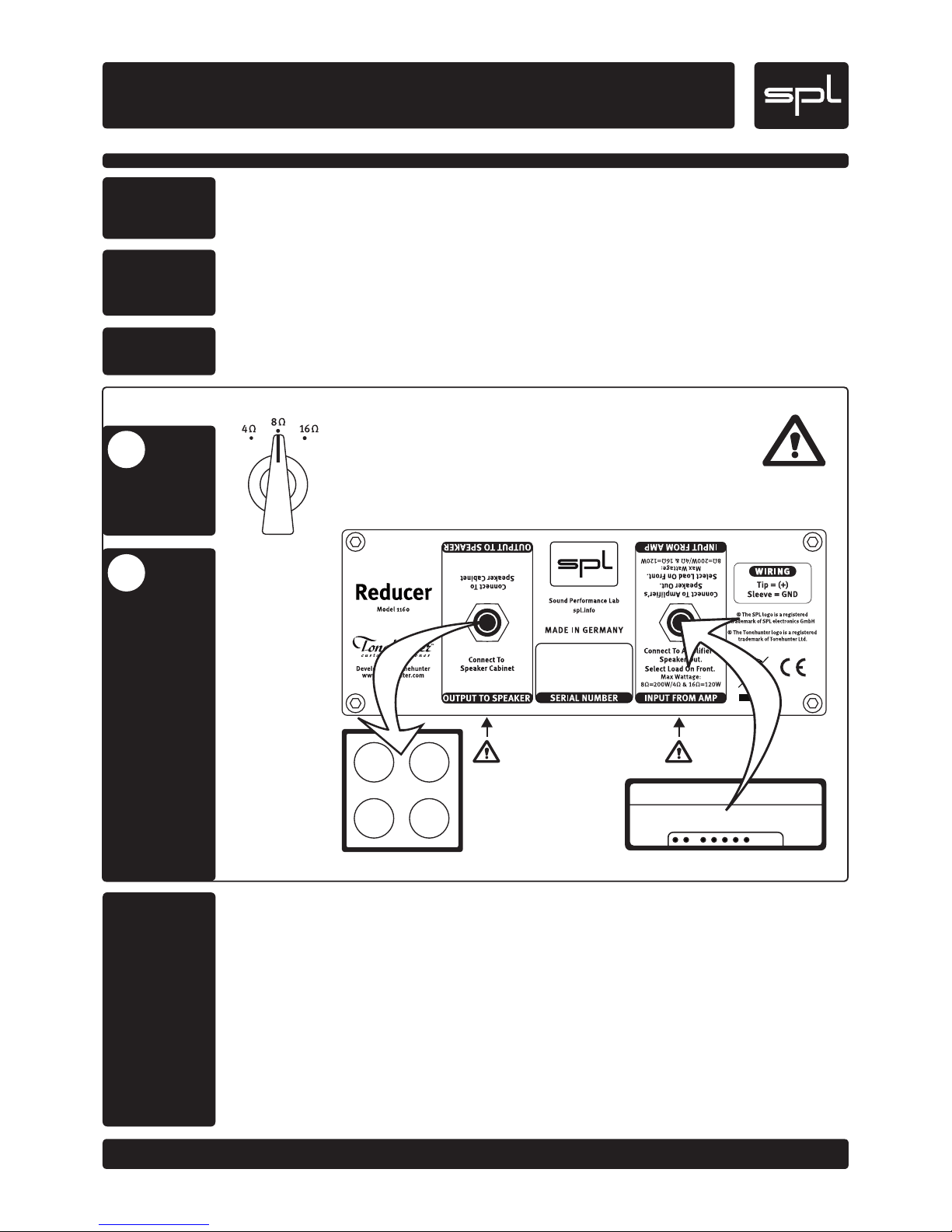
IMPORTAN T: Before connecting an amp, select the appropriate impedance
for it with the front panel Impedance Switch (refer to “Impedance Switch”
on page 2). Never reduce impedance while playing!
The Reducer is a passive device and needs no electrical power. Af ter the impedance is
set, connect guitar amp and cabinet as shown below.
In order to avoid health risks and equipment damage: Do not use this machine anywhere near water (wash basin,
swimming pools, or the like). Only use the connections as described. Never allow any fluids to be spilled or
sprayed on the machine or a foreign object through any of the machine‘s chassis openings.
Never cover or otherwise close off chassis openings to protect the unit from overheating. Never place the unit on
a soft surface (carpet, sofa, etc.). Make sure to provide for a mounting space of 5 cm/2 inches to the sides and top
of the unit when mounting the unit in racks or on cabinets. Placing the unit upon a guitar amplifier is obvious and
intended: the height of the feet is sufficient to also place the Reducer above a handle.
The Reducer converts electrical energy into heat. It can get considerably hot if high energy levels have to be
reduced. This is no reason for concern as long as you ensure to keep the max. input levels listed under “Specs”
on page 2. Side and top panels are cooling surfaces. Only touch with caution! Keep all objects at a safe distance!
Here you connect the amp‘s loudspeaker output. Connector variant and pin configurations follow industry
standards: Unbalanced 1/4" jack (TS) connector with the signal at the tip and ground at the sleeve. As with any
typical amp and cabinet cabling, it is critical to observe loudspeaker cable of a minimum 1.5 mm2 cross section.
Instrument or line cables can lead to amplifier damage! We recommend to use cables with a maximum length of
3 meters/10 feet for lossless signal transmission.
IMPORTANT WARNING ON CONNECTING GUITAR AMPS
Many guitar amps are not designed for sustained maximum level operation, and if run this way, it can lead to
overloads and power amp damage. At high levels, amps can produce high frequency oscillations which can
destroy output transformers. Moreover, this can cause audible unwanted output transformer distortion. Such
problems are not a result of Reducer use, but reside within the guitar amp. Even in situations where you might
wish to push the guitar amp to its limits in conjunction with the Reducer, you should always be sure to allow for
ample power reserves to avoid endangering the amp itself! Reducer this way. Therefore we strongly recommend
that the guitar amp should never be run at over 70% of its maximal signal level!
Guitar/Bass Amp
Cabinet
USE SPEAKER CABLE
Further information: spl.info
Page 1/2
Hook Up
2
1
Page 2
Reducer
Model 1160
Quick Guide
Page 2/2
Output
Reduction
Switch
Reduction
Control
Impedance
Switch
Specs
Passive Power Soak For Guitar & Bass Amplifiers • Point To Point Handwired
© 2011 SPL electronics GmbH. All rights reserved.
At the OUTPUT the amp signal appears as reduced with the front panel controls. It allows for the connection of a
4, 8 or 16 ohm cabinet. Reduction starts at 0 dB (unity gain) followed by two -3 dB and -5 dB switch settings. The
variable values range from -7 dB to infinite. With this “volume control” between amp and cab, the guitar amp can
be driven into saturation also at moderate listening levels.
Connector variant and connections follow industry standards: Unbalanced 1/4" jack connector with the signal
at the tip and ground at the sleeve. As with any typical amp and cabinet cabling, it is critical to observe loud-
speaker cable of a minimum 1.5mm2 cross section. Instrument or line cables can lead to amplifier damage! We
recommend to use cables with a maximum length of 3 meters/10 feet for lossless signal transmission.
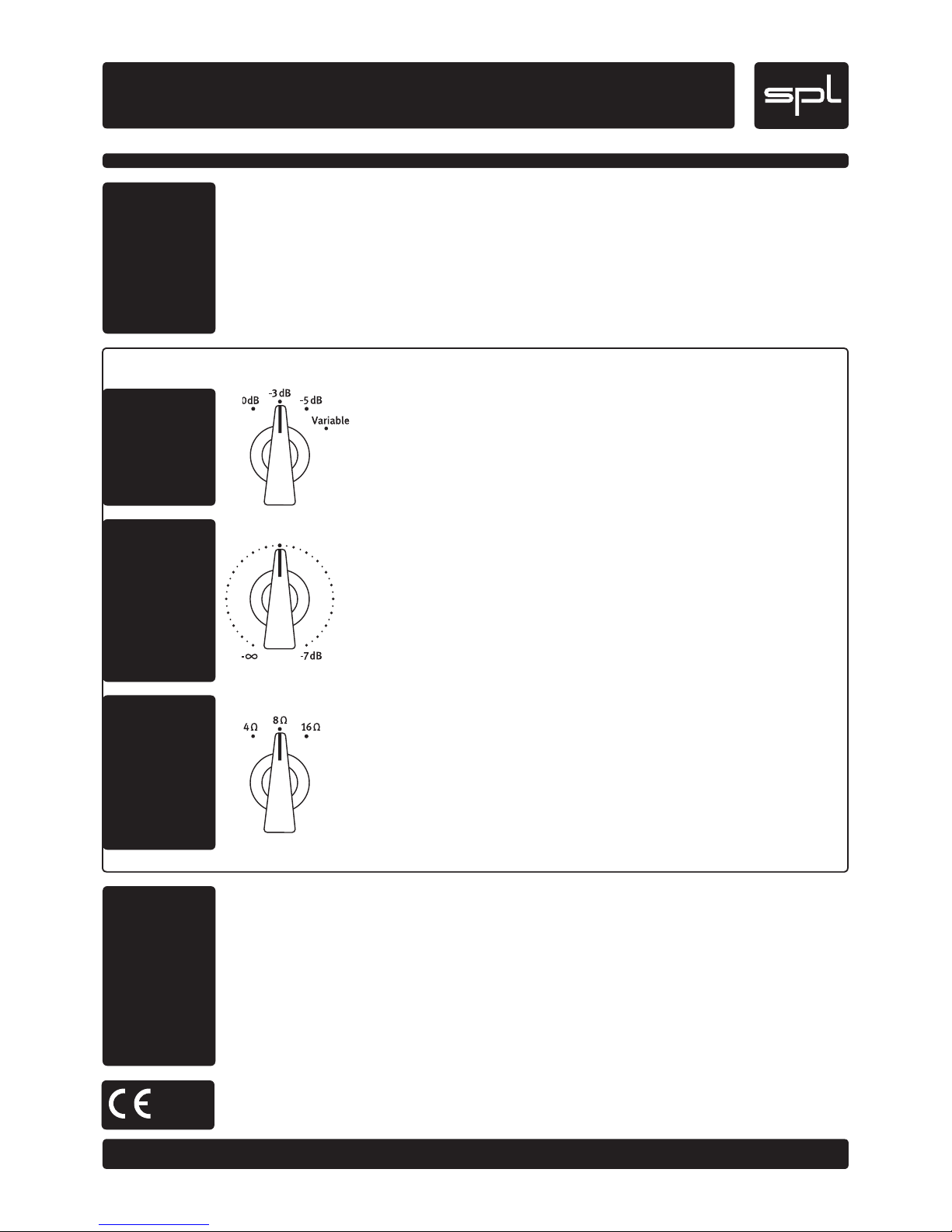
With the REDUCTION SWITCH on the left side of the front panel you selec t the first reduction values: 0 dB (unity gain), -3 dB, and -5 dB. Selecting the VARIABLE switch position
activates the central REDUCTION CONTROL for further, continuous reduction ranging
from -7 dB to infinite (mute).
The central REDUCTION CONTROL is only active when the REDUCTION SWITCH is set to
VARIABLE.
Set fully left mutes the signal, turned fully right results in a power reduction
of -7 dB. A 7 dB reduction can be compared approximately to the volume that results
from a “half power“ setting at guitar amps; usually this is still pret ty loud in many situations.
With the IMPEDANCE SWITCH to the right you select the required impedance for your
amplifier. Check the impedance of your amplifier at its speaker output.
IMPORTANT: Just as with any cabinet connection, selecting an impedance lower than
needed can destroy the amplifier. Therefore, double check selection of the appropriate
impedance before use. Never reduce impedance while playing!
Selecting a higher impedance than necessary does not harm any device. Whenever you
may be in doubt about the required impedance for an amp, select the highest impedance
(16 ohms) – you may lose power, bot not your amp.
Input Socket: 1/4" TS (Mono Jack)
Impedance 4, 8, or 16 Ohms switchable
Max. input load @4 Ohms: 90 W RMS/120 W Peak
@8 Ohms: 200 W RMS/260 W Peak
@16 Ohms: 160 W RMS/180 W Peak
Output Socket: 1/4" TS (Mono Jack)
Dimensions Height 68 mm, 85 mm with feet
Depth 190 mm, 208 mm with controls and sockets
Width 179 mm
Weight 1,8 kg/3.97 lbs
The construction of the REDUCER, Model 1160, is in compliance with the standards and
regulations of the European Cummunity.
Further information: spl.info
Page 2/2
Control Elements
 Loading...