

Page 1
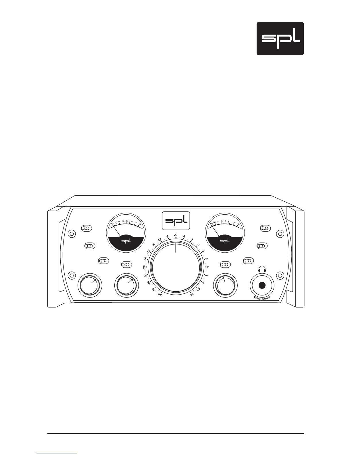
Manual
Phonitor
Headphone Monitoring Amplifier
Model 2730
1
5
°
2
2
°
3
0
°
4
0
°
5
5
°
7
5
°
-
2
.
0
-
1
.
6
-
1
.
2
-
0
.
9
-
0
.
6
-
0
.
3
d
B
C
E
N
T
E
R
L
E
V
E
L
OFF
ON
OFF
ON
METER CAL.
METER MODE
VU PPM
+60
-2 0
MONO
CROS./SPK. CENTER
OFF ON OFF
SOLO
L R
OFF
Ø
L R
OFF
S
P
E
A
K
E
R
A
N
G
L
E
C
R
O
S
S
F
E
E
D
M
I
N
2
3
4
5
M
A
X
DIM
120 V Rail Headphone
Monitoring Amplifier
Phonitor
Model 273 0
V
O
L
U
M
E
Page 2
2
Phonitor
Manual Phonitor
Model 2730
Version 1.0 – 5/2008
Designer: Wolfgang Neumann, Hermann Gier
This user‘s guide contains a description of the product. It in no way represents
a guarantee of particular characteristics or results of use. The information in
this document has been carefully compiled and verified and, unless otherwise
stated or agreed upon, correctly describes the product at the time of packaging
with this document.
Sound Performance Lab (SPL) continuously strives to improve its products and
reserves the right to modif y the product described in this manual at any time
without prior notice. This document is the property of SPL and may not be copied
or reproduced in any manner, in part or fully, without prior authorization by SPL.
SPL electronics GmbH, Sohlweg 80, 41372 Niederkruechten, Germany
Phone. +49 (0)2163 983 40
Fax +49 (0)2163 983 420
E-Mail: [email protected]
Internet: www.soundperformancelab.com, www.spl-usa.com
CE Declaration of Conformity
Manufacturer: SPL electronics GmbH, Type of Equipment: Audio Signal
Processor, Product: Phonitor, Model 2730, Compliance Engineer:
Wolfgang Neumann
Test Basis: EN50081-1:1992, EN50082-1:1992, EN60065:1993, EN61000-3-3:1995,
EN60065:2002, EN55013:2001, EN55020:2002, EN61000-3-2:2000, 73/23 EWG;
93/68 EWG. We herewith declare, that the construction of the Phonitor, Model
2730, is in compliance with the standards and regulations mentioned above.
Notes on Environmental Protection
At the end of its operating life, this product must not be disposed of
with regular household waste but must be returned to a collection
point for the recycling of electrical and electronic equipment. The
“wheelie bin“ symbol on the product, user‘s manual and packag-
ing indicates that. The materials can be re-used in accordance with their mark-
ings. Through re-use, recycling of raw materials, or other forms of recycling of
old products, you are making an important contribution to the protection of our
environment. Your local administrative office can advise you of the responsible
waste disposal point.
WEEE Registration: 973 349 88
© 2008 SPL electronics GmbH. All rights reserved. Names of other companies
and their products are trademarks of their respective owners.
Page 3

Phonitor
3
Symbols And Notes, Scope of Delivery ............................. 4
Important Security Information ..................................... 5
Hook Up .............................................................. 7
Introduction .......................................................... 8
Applications .. .. ... .. .. ... .. ... .. ... .. ... .. .. ... .. ... .. ... .. .. ... .. 9
A New Kind Of Headphone Amplifiers:
Headphone Monitoring Amplifiers . . . . ... .. .. ... .. ... .. ... .. ... .. 9
With And Without Magnifiers .. . . ... .. ... .. ... .. .. ... .. ... .. ... .. 9
The End Of Ear Fatigue . .. ... .. .. ... .. ... .. ... .. ... .. .. ... .. ... .. .. 10
Rear Panel/Connections ............................................ 12
Wiring . . . . ... .. ... .. ... .. .. ... .. ... .. ... .. .. ... .. ... .. ... .. ... .. .. .. 12
Voltage, Power Connection, Power, XLR Connectors . . .. .. ... .. . 13
Pin Wiring XLR Connectors, GND Lift Switch .. .. ... .. ... .. ... .. .. 14
Front Panel/Connection ............................................. 15
Headphone Connection, Recommendations, Warning . .. ... .. .. 15
Control Elements .................................................... 16
Crossfeed, Speaker Angle .. . . .. .. .. ... .. ... .. ... .. ... .. .. ... .. ... 16
Interaural Level and Time Differences
as Related to Crossfeed Setup . .. ... .. ... .. .. ... .. ... .. ... .. .. ... 17
Interaural Level and Time Differences
as Related to Speaker Angle Setup .. .. .. ... .. ... .. .. ... .. ... .. .. 18
Table: Crossfeed and Speaker Angle Parameters . . . ... .. ... .. .. 19
CROS./SPK., Center Level, Center Off/On . .. .. ... .. ... .. ... .. ... . 2 0
VU Meter, Signal LED, Overload LED .. . . ... .. ... .. .. ... .. ... .. ... 21
Meter Mode, Meter Cal., Dim ... .. .. ... .. ... .. ... .. .. ... .. ... .. ... 22
Solo, Phase Ø .. . . . ... .. ... .. .. ... .. ... .. ... .. .. ... .. ... .. ... .. ... . 23
Mono, Volume .. .. .. ... .. .. ... .. ... .. ... .. .. ... .. ... .. ... .. ... .. .. 24
OPERATION: Quick Guide to Headphone Monitoring ........... 25
Adjust Headphone Reproduction to Loudspeaker Monitoring . . . 25
Specifications ....................................................... 28
Measurements ...................................................... 29
Frequency Response, Phase Response . .. ... .. ... .. ... .. .. ... .. . 29
THD vs. Output Level, THD vs. Frequency . . . ... .. ... .. ... .. .. ... . 30
Copy Master: Recall Settings ....................................... 31
Guarantee ............................................................ 32
Contents
Page 4
4
Phonitor
Symbols and Notes
Scope Of Delivery
Symbols And Notes
IN THIS MANUAL A LIGHTNING SYMBOL WITHIN A TRIANGLE WARNS
YOU ABOUT THE POTENTIAL FOR DANGEROUS ELECTRICAL SHOCKS
– WHICH CAN ALSO OCCUR EVEN AFTER THE MACHINE HAS BEEN
DISCONNECTED FROM A POWER SOURCE.
AN EXCLAMATION MARK (!) WITHIN A TRIANGLE IS INTENDED TO MAKE
YOU AWARE OF IMPORTANT OPERATIONAL ADVICE AND/OR WARNINGS
THAT MUST BE FOLLOWED. BE ESPECIALLY ATTENTIVE TO THESE AND
ALWAYS FOLLOW THE ADVICE THEY GIVE.
The symbol of a lamp directs your attention to explanations of important functions or applications.
Attention
Do not attempt any alterations to this machine without the approval
or supervision of SPL electronics GmbH. Doing so could nullify completely any and all of your warranty/guarantee rights and claims to
user support.
• Phonitor, Model 2730
• This manual
• Power cord
Page 5
Phonitor
5
Important Security Information
Please note and retain this manual. Carefully read and follow all of the
safety and operating instructions before you use the machine. Be doubly careful to follow all warnings and special safety instructions noted
in this manual and on the unit.
Connections: Only use the connections as described. Other connections can lead to health risks and equipment damage.
Water And Humidity: Do NOT use this machine anywhere near water
(for example near a wash basin or bath, in a damp cellar, near swimming pools, or the like). In such cases there is an extremely high risk of
fatal electrical shocks!
Insertion Of Foreign Objects Or Fluids: NEVER allow a foreign object
through any of the machine‘s chassis openings. You can easily come
into contact with dangerous voltage or cause a damaging short circuit.
NEVER allow any fluids to be spilled or sprayed on the machine. Such
actions can lead to dangerous electrical shocks or fire!
Opening the Machine: Do NOT open the machine housing, as there is
great risk you will damage the machine, or – even after being disconnected – you may receive a dangerous electrical shock!
Electrical Power: Run this machine ONLY from sources which can
provide proper power at the prescribed rating. When in doubt about
a source, contact your dealer or a professional electrician. To be sure
you have isolated the machine, do so by disconnecting the power cord
from your wall connection. Be sure that the power cord plug is always
accessible. When not using the machine for a longer period, make sure
to unplug it from your wall power socket.
Power Cord Protection: Make sure that your power cord is arranged
to avoid being stepped on or any kind of crimping and damage related
to such event. Do not allow any equipment or furniture to crimp this
power cord.
Power Connection Overloads: Avoid any kind of overload in connections to wall sockets, extension or splitter power cords. Always keep
manufacturer warnings and instructions in mind. Overloads create fire
hazards and risk of dangerous shocks!
Lightning: Before thunderstorms or other severe weather, disconnect
the machine from wall power (but to avoid life threatening lightning
strikes, not during a storm). Similarly, before any severe weather, disconnect ALL the power connections of other machines and antenna and
phone/network cables which may be interconnected so that no lightning damage or overload results from such secondary connections.
Page 6

6
Phonitor
Air Circulation: Chassis openings offer ventilation and serve to protect
the machine from overheating. NEVER cover or otherwise close off
these openings. NEVER place the machine on a soft surface (carpet,
sofa, etc.). Make sure to provide for a mounting space of 4-5 cm/2 inches when mounting the machine in racks or cabinets.
Controls And Switches: Operate the controls and switches only as
described in the manual. Incorrect adjustments outside safe parameters can lead to damage and unnecessary repair costs. Never use
the switches or level controls to effect excessive or extreme changes.
Repairs: Unplug the machine and immediately contact a qualified
technician when you think repairs are needed – or when moisture or
foreign objects may accidentally have gotten in to the housing, or in
cases when the machine may have fallen and shows any sign of having been damaged. This also applies to any situation in which the machine has not been subjected to any of these unusual circumstances
but still is not functioning normally or its performance is substantially
altered.
In cases of damage to the power cord or its plug, first consider turning
off the main circuit breaker before unplugging the power cord.
Replacement/Substitute Parts: Be sure that any service technician
uses original replacement parts or those with identical specifications
as the originals. Incorrectly substituted parts can lead to fire, electrical
shock, or other dangers, including further equipment damage.
Safety Inspection: Be sure always to ask a service technician to conduct a thorough safety check and ensure that the state of the repaired
machine is in all respects up to factory standards.
Cleaning: In cleaning, do NOT use any solvents, as these can damage
the chassis finish. Use a clean, dry cloth (if necessary, with an acid-free
cleaning oil). Disconnect the machine from your power source before
cleaning.
Important Security Information
Page 7
Phonitor
7
Be very careful to check that the rear chassis power selection switch
is set to the correct local line voltage position before using the unit
(230 V position: 220-240 V/50 Hz, 115 V position: 110-120 V/60 Hz)!
When in doubt about a source, contact your dealer or a professional
electrician.
Before connecting any equipment make sure that any machine to be
connected is turned off. Follow all safety instructions from page 5.
Place the unit on a level and stable surface. The unit’s enclosure is EMCsafe and effectively shielded against HF interference. Nonetheless, you
should carefully consider where you place the unit to avoid electrical
disturbances. It should be positioned so that you can easily reach it,
but there are other considerations. Try not to place it near heat sources
or in direct sunlight, and avoid exposure to vibrations, dust, heat, cold
or moisture. It should also be kept away from transformers, motors,
power amplifiers and digital processors. Always ensure sufficient air
circulation by keeping a distance of 4-5 cm/2 inches to other units and
to the sides of the unit.
Before You Begin
Make sure the Volume control is turned hard left before you power up
the unit. Now control Volume. Note that too high levels can damage
headphones and hearing!
Hook Up
Page 8
8
Phonitor
Introduction
There is more than meets the eye in working with headphones. A reason for this surely lies in that modern audio production often necessitates decentralized processes. In turn, production phases following
such plans more often take place in acoustically questionable rooms.
In such circumstances, a mix might occur in an acoustically deficient
ambiance (for example, in an extremely modal room), and employing
headphones then begins to make sense when a successful mix would
otherwise turn out to be impossible.
But another fact is that many musicians or producers might wish to – or
be able to – mix at home (to say nothing of having to). Then the headphone becomes a clear must, enabling an evening or late night session
that can only take place thanks to its being unhindered by the local
acoustic environment.
Each and every careful headphone user should know about the analytical advantages of headphone monitoring, but also about the main
disadvantage: the difficulty (if note impossibility) in properly judging
room ambiance.
Therefore, several years ago SPL began planning the development of
a compact, professional headphone amplifier design based on its 120
volt technology. The essential inspiration came from project manager
Hermann Gier‘s desire to eliminate the major disadvantage in working
with headphones. It therefore meant transferring essential ambient
parameters of loudspeaker monitoring to the headphone monitoring.
After several years of development and painstaking optimization, we
can now introduce the Phonitor, whose derivative name from combining “Headphone“ and “Monitor“, conveys the successful conclusion of
this process.
At first glance the Phonitor‘s functional range makes immediately
clear that this is not just another headphone amplifier. With the usual
(monitoring) parameters there are new functions such as “Crossfeed“,
“Speaker Angle“ and “Center Level“. These are the essential parameters to create what with loudspeaker monitors are perception of width,
balance and overall space and how we recognize them coming from
the loudspeaker. Crossfeed simulates the frequency dependent interaural level differences from both channels. Speaker Angle determines
the stereo width caused by frequency dependent interaural time differences. Center Level regulates the balance between phantom center
and L/R stereo signals.
Page 9

Phonitor
9
Applications
Aside from its outstanding abilities as loudspeaker substitute the
Phonitor offers well equipped studios a fully functional monitoring
alternative.
In addition one can take along the Phonitor into an unfamiliar studio
or production environment that always provides the engineer’s own
monitor sound.
Furthermore, with the Phonitor one can simply enjoy music as it was
originally mixed, namely for playback over loudspeakers.
A New Kind Of Headphone Amplifiers:
The Headphone Monitoring Amplifiers
The Phonitor design is our high-end interpretation for what a complete
headphone amplifier should be. A well chosen system of Phonitor and
headphones can by and large replace loudspeakers and offers best
requirements for a fatigue-free hearing and successful work sessions.
We therefore refer to the Phonitor as a headphone monitoring amplifier
system.
The basis for this high-end development is our proved 120 volts reference technology based upon our own, handmade operation amplifier. It corresponds to approximately twice that of most modern analog
audio semiconductor technologies. Through such 120 volts circuitry
and processing we reach performance levels far beyond conventional
designs in dynamic range and distortion levels.
Such technical specifications exceed all known analog or digital standards (please also refer to the chapter “The End of Ear Fatigue” from
page 10).
With And Without Magnifiers
The Phonitor encompasses advantages of both kinds of monitoring
methods: On one hand the analytical headphone monitoring is like
working with an acoustic magnifier but without external room influences; on the other hand, loudspeaker monitoring forgoes the microscopic
effect, but provides for room ambiance.
Working with the magnifier effect of headphones has the advantage of
safely hearing clicks or similar defects and helps in fine tuning crossfades or to judge tonal problems in individual tracks. >
Introduction
Page 10

10
Phonitor
With And Without Magniers, The End Of Ear Fatigue
Introduction
On loudspeakers such analyses are much more difficult, as such problems just are not as apparent when one is working without being able
to “zoom in” aurally.
Conversely, loudspeakers provide monitoring with the advantage of
spatial balance in a (definable through placement) stereo width, which
in turn provides the illusion of an acoustic stage.
Traditional headphone reproduction produces one 180-degree stereo
width in the middle of the head, and it is exactly this which creates the
very problematic-to-impossible headphone mixing environment. An essential reason for such unnatural ambiance is the complete separation
of the channels, which does not exist either in natural hearing or in stereo loudspeaker reproduction. This makes it nearly impossible to judge
tonal balance, a stereo image and the phantom center level. Panorama
adjustments as well as related EQ settings that one attempts with
headphones, typically just do not function on loudspeakers.
Moreover, what is often called the “super stereo effect” with headphones usually creates a great deal of ear fatigue in the long run. Over
loudspeakers the sound stage is felt in front, while in contrast, when
monitoring through headphones, the stage is present on the left and
on the right – but frontal and rear information is lost.
The End Of Ear Fatigue
Aside from these unnatural headphone ambiance there are further disadvantages with fatigue when mixing or listening with headphones.
First, some cans themselves may not be that comfortable to wear...
Moreover, a standard headphone amplifier is often an additional important reason for premature ear fatigue. Almost without exception,
present-day headphone amplifiers employ comparatively undemanding IC’s. In the best cases they might work with symmetrical voltages of
+/-15 V to +/-18 V, and in less favorable cases, with only a simple supply
of 9 or 12 V from cheaper external “wall-wart“ power supplies.
But the voltage level acts in circuitry much like the cubic inch capacity
to the productive power of a combustion engine: Cubic inch capacity is
replaceable with nothing but more cubic inch capacity – and in the productive power of electronics, voltage level functions similarly.
Page 11

Phonitor
11
The End Of Ear Fatigue
Introduction
For some years, now, SPL has addressed this issue in all of its mastering product series through its own specifically developed 120 volt technology. Consoles and signal processors of the SPL Mastering Series
appear as central elements in installations of today’s most renowned
mastering houses (z. B. Bob Ludwig’s Gateway Mastering & DVD in the
USA, Simon Heyworth’s Super Audio Mastering in Great Britain or the
Galaxy Studios in Belgium).
This 120 volt technology is based on discrete operation amplifiers
from SPL’s own production, developed and perfected over many years
by SPL’s co-founder and chief developer, Wolfgang Neumann. These
SUPRA OPs work with high-performance semiconductors in Class A
technology at a symmetrical voltage of +/-60V.
In the Phonitor nine SUPRA OPs are employed. The SUPRA OPs have a
Signal To Noise Ratio of 116 dB and offer a nearly 34 dB headroom – that
yields an unequalled 150 dB dynamic range.
The musical result is not to be mistaken: Regardless of the monitoring means, regardless of how loud you monitor – the Phonitor always
remains a distant, impartial factor unaffected when used to capacity
and beyond being overloaded. The phase stability is always perfect,
its THD next to immeasurable. The Phonitor’s SUPRA OPs cannot be
stressed in the most stressful circumstances, and for precisely this
reason its musical sound is always relaxed and spacious. All frequencies are reproduced in balance, basses are stable and tight, mids are
clear and differentiated and highs remain transparent and soft.
Such supreme and heretofore unreachable neutrality in audio reproduction is the direct consequence of our technical approach and basis
in 120 volt technology: Possible disturbances from such as noise or distortion are so slight that we even arrive at the boundaries of the best
measuring equipment, and what remains is quite simply unaltered musical sound.
Page 12
12
Phonitor
Rear Panel/Connections
Wiring
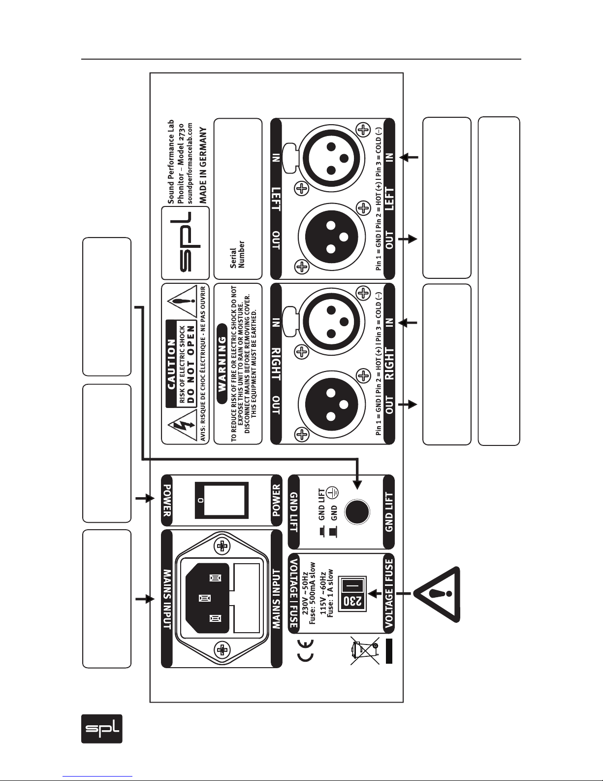
Make sure that the voltage switch setting
reflects the correct local power line voltage.
Input & Output
Right Channel
The Phonitor can be fed from any stereo signal path via its
rear panel XLR sockets. Headphone connection on the front panel.
Input & Output
Left Channel
Power Supply
Connection
Power
Switch
GND Lift
Switch
Page 13
Phonitor
13
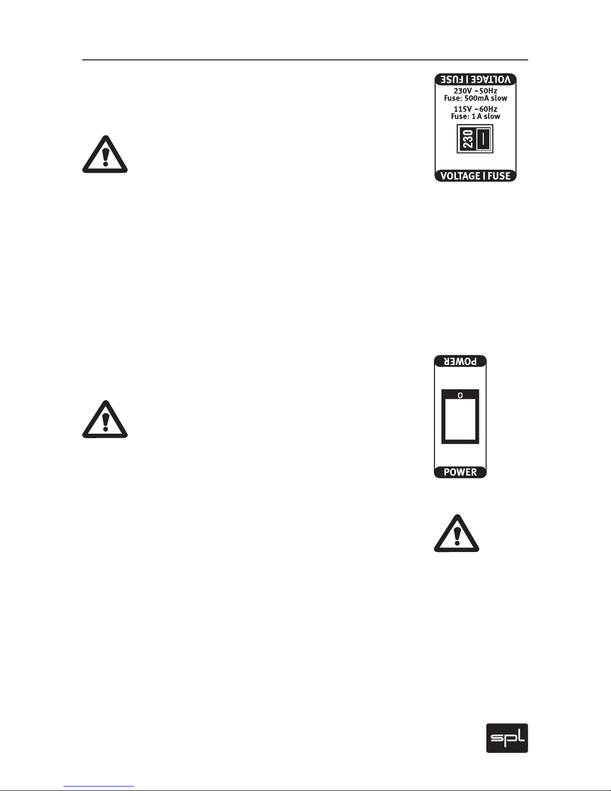
Voltage
The rear panel voltage selector switch serves to let the user switch to
the local line voltage standard.
IMPORTANT ADVICE: Before you use the Phonitor, make
sure that this switch setting reflects the correct local power
line voltage (115 V position: 110-120 volts/6o Hz, 230 V
position: 220-240 volts/50 Hz).
Power Connection
Connect the included power cord to the rear Mains Input. Transformer,
power cord and case connection conform to VDE, UL and CSA requirements. Power fuse ratings are 500 mA slow blow (
220-240
volts) or 1 A
slow blow (
110-120
volts).
Power
The rear panel Power switch activates the unit, confirmed by the lighted VU meters.
IMPORTANT ADVICE: Switch on the unit only after you have
turned the Volume control fully left, and wait to set your desired volume level until the unit is powered on. Neglecting
this can damage either or both your ears and your headphones!
XLR Connections
Switch off the unit before you begin the process of making the first
or any subsequent connections (rear panel Power switch). Neglecting
this can damage either or both your ears and your headphones!
Connect the monitoring signal to the left and right channel XLR input
sockets. Both XLR outputs transmit the monitoring signal unaltered
so that no additional monitoring output is needed for insertion of the
Phonitor. Input and output stages are electronically balanced. They
ensure high common mode rejection and drive long cable connections
(depending on cable capacities and following input stages).
Rear Panel/Connections
Connections & Switches
Page 14
14
Phonitor
Pin Wiring XLR Connectors, GND Lift
Rear Panel/Connections
Pin Wiring XLR Connectors
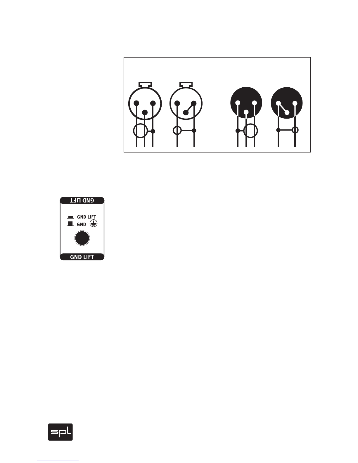
The diagram shows how to wire the balanced XLR connections if unbalanced connections are required.
GND Lift
The rear panel GND lif t switch eliminates hum by separating the internal ground from the unit’s housing ground. Hum can, for example, result when this unit’s housing has a common ground connection with
other machines that might have a different ground potential.
Input
Output
balanced
unbalanced
balanced
unbalanced
1=GND
2= hot (+)
3= cold (-)
1
2
3
1
2
3
1
2
3
1
2
3
Page 15
Phonitor
15
Front Panel/Connection
Headphone Connection
Headphone Connection
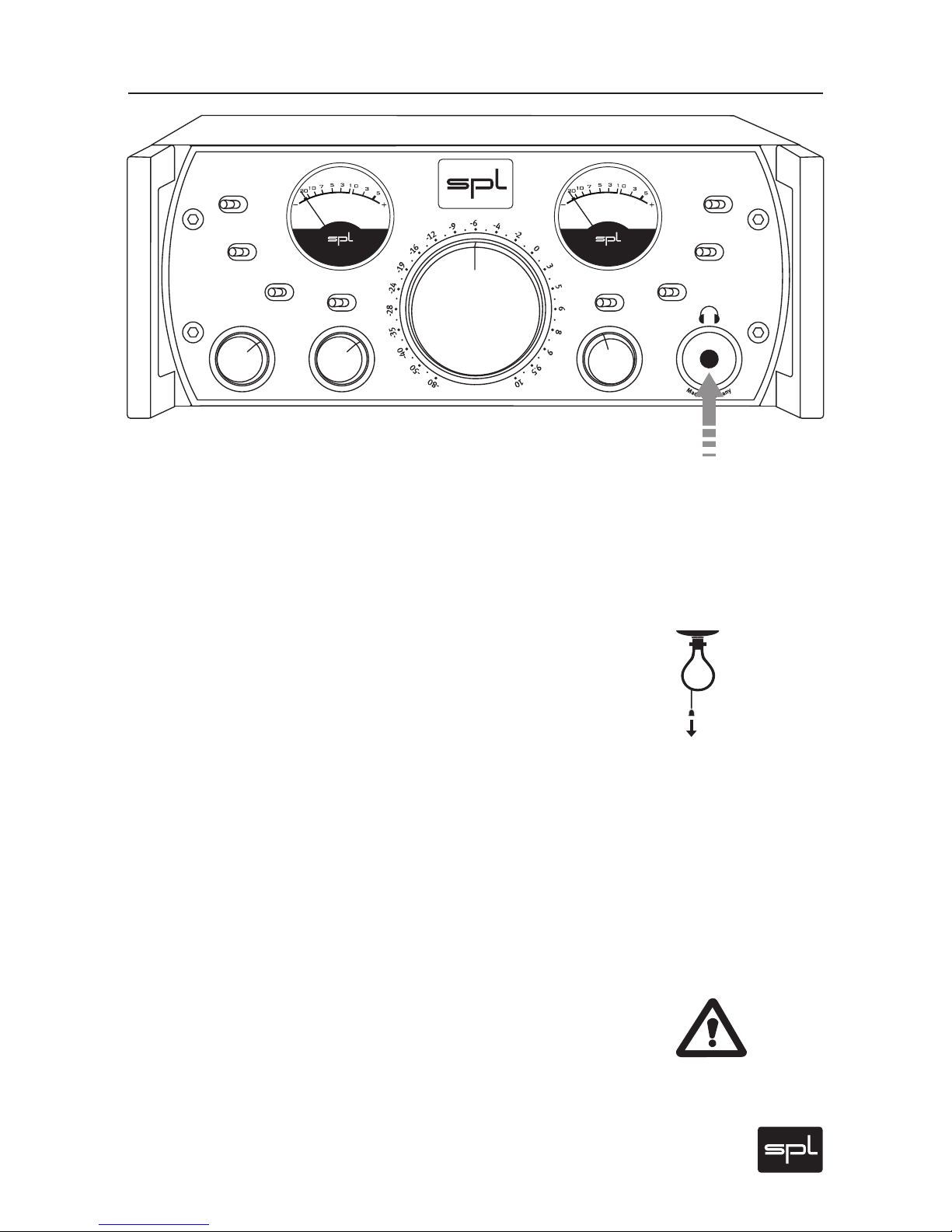
Connect headphones to the standard 1/4” (TRS) stereo plug on the
lower right front panel. The layout is: Tip =left channel, Ring = right
Channel, Sleeve = ground.
Make sure that the plug firmly seated for a solid connection.
Recommendations
Unplug the headphone when you switch off the Phonitor. Otherwise
discharging residual voltages can cause beeping sounds. We did not
add a circuitry to avoid that phenomenon as it would have compromised sound quality.
Reduce volume level before you remove or plug in the headphone (or
when switching headphones). This excludes louder clicks and pops
reaching the ear. In addition, this can avoid unpleasant surprise that
follows when a headphone’s lower impedance suddenly reproduces an
otherwise acceptable Phonitor volume setting of a first headphone at a
much higher – even painful – level.
Warning
NEVER plug in a mono 1/4“ to the headphone output. The use of a
mono 1/4“ will lead to a short-circuit that will destroy the final amplifier stage! Standard headphone connectors always have stereo plugs,
and thus a correct connection will be assured when you only connect
headphones directly.
1
5
°
2
2
°
3
0
°
4
0
°
5
5
°
7
5
°
-
2
.
0
-
1
.
6
-
1
.
2
-
0
.
9
-
0
.
6
-
0
.
3
d
B
C
E
N
T
E
R
L
E
V
E
L
OFF
ON
OFF
ON
METER CAL.
METER MODE
VU PPM
+60
-2 0
MONO
CROS./SPK. CENTER
OFF ON OFF
SOLO
L R
OFF
Ø
L R
OFF
S
P
E
A
K
E
R
A
N
G
L
E
C
R
O
S
S
F
E
E
D
M
I
N
2
3
4
5
M
A
X
DIM
120 V Rail Headphone
Monitoring Amplifier
Phonitor
Model 273 0
V
O
L
U
M
E
Page 16
16
Phonitor
Crossfeed, Speaker Angle
Crossfeed
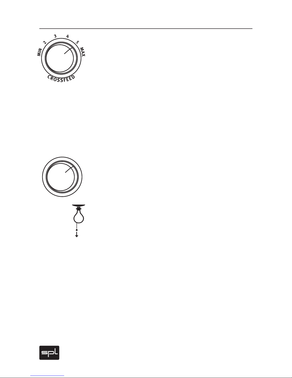
The Crossfeed switch allows you to adjust the frequency-dependent
crossfeed simulation of both channels by adjustments of interaural
level difference – as if this characteristic would be heard from monitors when in their own room ambiance. One can compare variations
in crossfeed values as approximating the influence of different room
sizes and characteristics on a given loudspeaker setup.
This adjustment can be made in six steps ranging from “minimum” to
“maximum”. Crossfeed interacts with the Speaker Angle value to simulate the width of a stereo image (please refer to the next section).
For further information regarding simulation of a specific loudspeaker playback setup, please refer to the “Quick Guide To Headphone
Monitoring“ on page 25.
Speaker Angle
The Speaker Angle switch provides for frequency-dependent simulation of your stereo image width by adjustments of interaural time difference. This influences the moment in time at which a signal‘s wave
form arrives at the ear and corresponds to a particular variation in the
angle of an actual loudspeaker pair.
The time constants of the interaural time differences between the left
and right channels occur within a range of 90 to 635 microseconds.
Compare the table “Crossfeed and Speaker Angle Parameters” on page
19. We recommend to start with the figures of the accentuated lines
from this mathematically-based table for a given monitoring setup. As
you might expect, however, the best results can only occur when you
follow the recommendations and then as needed, carefully engage in
your own additional fine tuning, especially between Speaker Angle and
the Crossfeed value.
For further information on the simulation of a specific loudspeaker
playback, please refer to the “Quick Guide To Headphone Monitoring“
on page 25.
Control Elements
1
5
°
2
2
°
3
0
°
4
0
°
5
5
°
7
5
°
S
P
E
A
K
E
R
A
N
G
L
E
Page 17
Phonitor
17
Crossfeed, Speaker Angle
Interaural Level and Time Differences as Related
to Crossfeed Setup
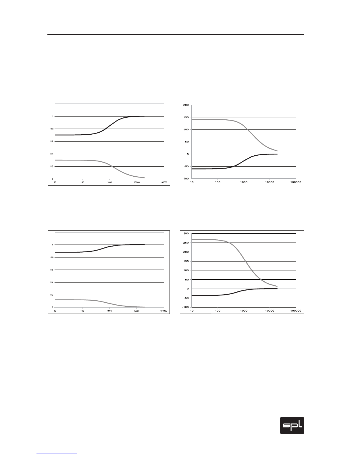
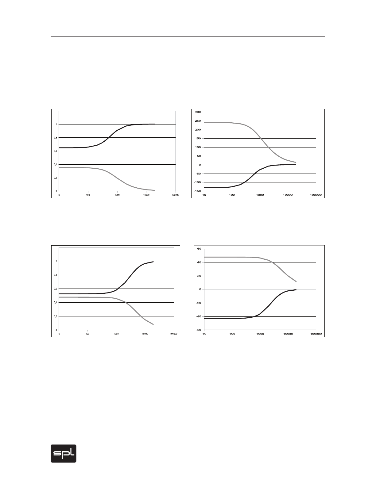
The following two diagrams show, respectively (on the left), the frequency response of interaural level differences and (on the right)
the interaural time difference at maximum Crossfeed value and at a
Speaker Angle of 30 degrees.
The following two diagrams show, respectively (on the left), the frequency response of the interaural level difference and (on the right) the
interaural time difference, at minimal Crossfeed value and a Speaker
Angle of 30 degrees.
The black curves stand for the side of the direct sound wave front,
while the gray curves stand for the opposite side. It is clearly recognizable that corrections are usually done for frequencies below 1 kHz.
You should also note that the Crossfeed control functions mainly level
dependent. Effects with respect to time differences are comparatively
slight. However, that they, too, may be altered is an indicator of interaction between Crossfeed and Speaker Angle control.
Control Elements
Page 18
18
Phonitor
Control Elements
Interaural Level and Time Differences as Related
to Speaker Angle Setup
The following two diagrams show (on the left) the frequency response
of interaural level difference with respect to the interaural time difference (on the right) at maximum Crossfeed value and a Speaker Angle
of 75 degrees.
The following two diagrams show, respectively (on the left), the frequency response of the interaural level difference and the interaural
time difference (on the right) at a maximum Crossfeed value and a
Speaker Angle of 15 degrees.
The black curves stand for the side of the direct sound wave front,
while the gray curves stand for the opposite side.
The larger the Speaker Angle value (and/or angle of an actual loudspeaker placement), the greater the effect will be of shifting the opposite side toward more deeply lying frequencies, since with an increased
spatial arc around the head only lower frequencies will undergo proportionate modification.
It should also become apparent that the Speaker Angle control is primarily depending on interaural time differences. Its influences on level
differences are in contrast, comparatively slight.
Crossfeed, Speaker Angle
Page 19

Phonitor
19
Crossfeed, Speaker Angle
Control Elements
Crossfeed and Speaker Angle Parameters
The accentuated lines show at which Crossfeed values the Speaker
Angle most precisely matches the theoretically determined time difference values. These, of course, are mainly a starting point to reproduce a
real monitoring setup.
Formulae for calculations from http://www.sengpielaudio.com/
LaufzeitdifferenzenBeimNatuerlichenHoeren.pdf
Speaker Angle
Switch
Crossfeed
Switch
Level
Difference
Time Diff.
(µs)
Speaker Angle
(Result)
Page 20
20
Phonitor
CROS./SPK., Center Level, Center Off/On
Control Elements
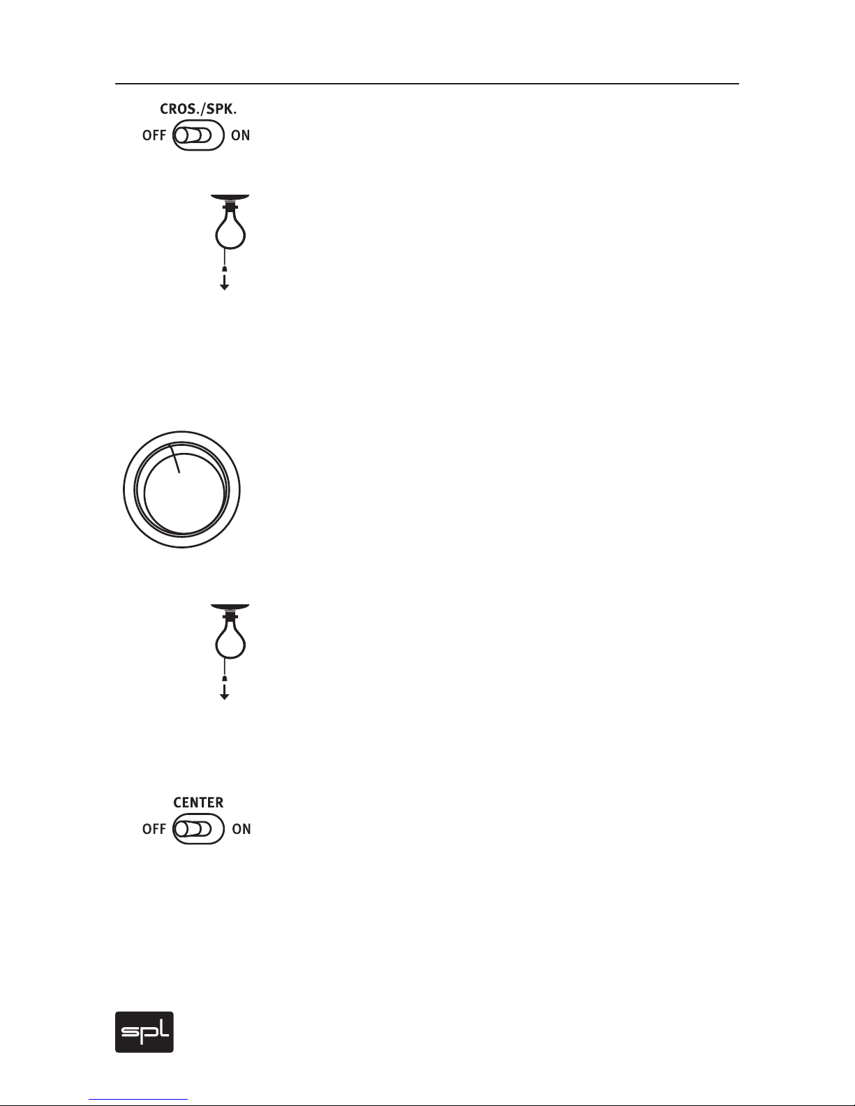
CROS./SPK.
With CROS/SPK. you switch on or off Crossfeed and Speaker Angle
functions globally. This provides for direct A/B comparisons.
Your impression may at first be that the results are not so spectacular
as expected – until you consider that the Phonitor is not an effects machine. Instead, reevaluate your aural impression by thinking about this:
normal headphone monitoring confronts you with a 180-degree sound
stage – the “super stereo width” has so little to do with loudspeaker
playback. Now you can gradually reduce this in 15 degree steps with
the Speaker Angle switch. Subsequently, using the Crossfeed function,
you can simulate the acoustic effect of room size and ambient characteristics on a given listening device.
Center Level
With the Center Level control you may regulate the intensity of center
signals to compensate for the stereo signal processing with Crossfeed
and Speaker Angle.
This Center Level signal is produced as a mono sum of the left and right
channels. Changes in these values are regulated through a finely graduated, six steps switch (0,3, 0,6, 0,9, 1,2, 1,6 and 2 dB).
In a normal headphone listening experience, the center signal is typically
quieter than the stereo signals, which appear much louder due to the
super stereo effect. If the signal width is narrowed through changes in
Crossfeed and Speaker Angle (so as to correspond to your actual loudspeaker setup), the headphone center may likely sound too intense now.
Lowering the center levels will again return the center signal to the correct volume in relation to the L/R stereo image.
Center Off/On
This switch activates or deactivates the Phonitor Center Level circuitry. In conjunction with both CROS./SPK. Off/On and CENTER Off/
On switches, it offers the choice between (conventional) headphone
amplifier setup and the Phonitor’s unique headphone monitoring amplifier setup.
-
2
.
0
-
1
.
6
-
1
.
2
-
0
.
9
-
0
.
6
-
0
.
3
d
B
C
E
N
T
E
R
L
E
V
E
L
Page 21
Phonitor
21
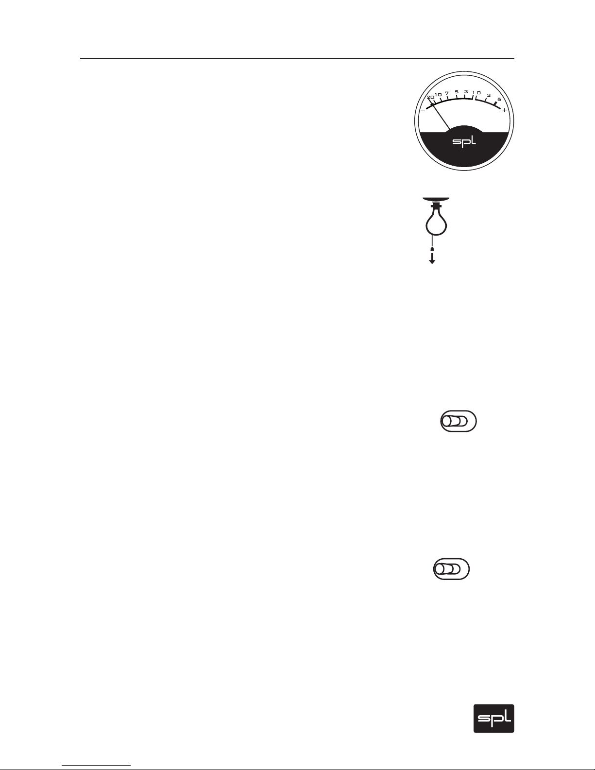
VU Meter
The VU meter displays the input level for each channel. The gauge indicates levels from -20 dB to +5 dB. If necessary you can lower the sensitivity by 6 dB so that the gauge goes up to +11 dB output level (see
“Meter Cal.“ on page 22).
The VU meter is custom made to meet SPL specifications and assures a
balanced optical perception thanks to it’s optimized ballistics.
An especially interesting feature is the option to switch between two
display modes: VU mode and PPM mode. The VU mode (VU=Volume
Unit) displays average levels to provide information on the overall
loudness. The PPM mode (PPM=Peak Program Meter) displays the
peak levels.
The integration time of the display complies with BBC requirements.
In VU mode the rise time up to 0 dB is approximately 300 ms. In PPM
mode the rise time up to 0 dB is about 2 ms and the release time down
to -20 dB is at a “slow” 1,5 seconds. This calibration ensures to display
even short peaks up to about +5 dB since the needle does not have to
travel the entire distance of the gauge every time.
Meter Mode
The Meter Mode switch allows to switch the VU metering characteristics from VU display mode to PPM display mode. In PPM mode, peak
levels are displayed – comparable for example to A/D converter displays. Monitoring peak levels is for example most important to avoid
overloading and to prevent audible distortion. Peak levels are always
above the average levels. It may make sense to choose the Meter Cal.
+6 dB switch position to extend the metering range.
Meter Cal.
With this switch you can change the sensitivity of the VU display. If you
choose the +6 dB position, the range of the display is extended by 6 dB.
With the +6 dB switch activated and the needle at 0 dB, a value of +6 dB
input level is displayed.
Control Elements
VU Meter, Signal LED, Overload LED
METER MODE
VU PPM
METER CAL.
+60
Page 22
22
Phonitor
Dim
The Dim function reduces the listening level (Volume) by around 20 dB.
Normally you employ this function when mixing to choose between
two defined volumes to avoid having to move the Volume control. A
dim value of 20 dB has established itself as good standard.
You can also use the Dim function to adjust among differences in
headphone impedance and the resulting sensitivity differences. The
Phonitor output and the optimal Volume level is based on the studio
standard, 600 Ohms headphone impedance.
However, there are many headphones which employ a lesser impedance, for example 250 Ohms or even only 50 Ohms. Such headphones
effect a much louder level. A 50 Ohms headphone thus yields a relatively loud minimum volume level. In such a case, the useful range of
an amplifier’s output level control or potentiometer is much more limited. Here you may use the Dim function to reestablish a useful range
for the volume control. The high component and circuitry quality of the
Phonitor guarantees that despite activating the Dim function there is
no measurable degradation of the signal quality.
Please note that the VU meter always displays the -20 dB damping
when Dim is activated. You may activate the +6dB Meter Cal. setting to
avoid that the needle sticks to the left – and add 14 dB to the displayed
values to translate to actual input levels.
Control Elements
Meter Mode, Meter Cal., Dim
-20OFF
DIM
Page 23
Phonitor
23
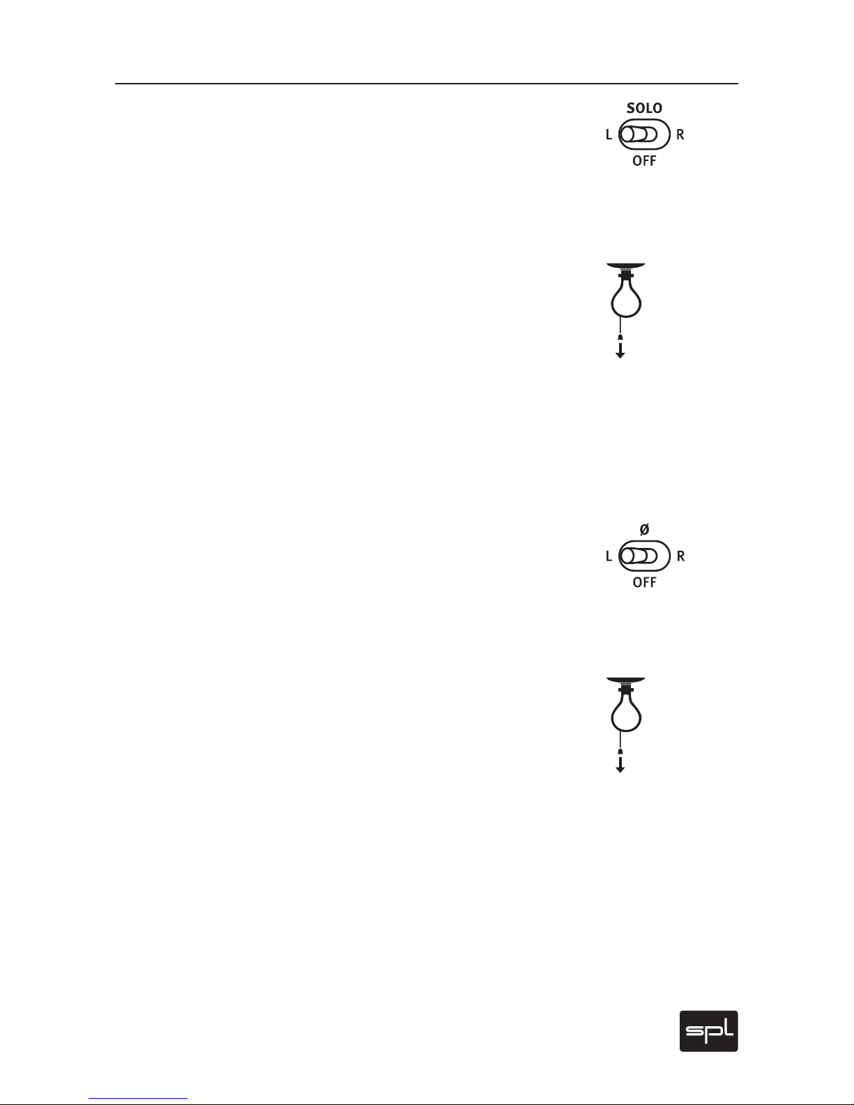
Solo
You can engage the solo switch to monitor only the left or right channel
of the stereo signal.
The Solo switch has three positions: L, R and OFF. The middle or OFF
position allows monitoring the stereo signal. Switched to L or R, and
you will hear only the left or right channels, respectively.
A selected solo channel defaults to retain in its respective left or right
position, and we call this function “Solo-in-Place”. However, should you
prefer to hear a chosen solo channel in both ears (“Solo-to-Center”),
you can additional active the Mono switch. This Solo-to-Center variant
also allows some interesting possibilities for comparison between two
channels. You can, for instance, recognize immediately whether the
sound of both channels contains comparably equal highs and mids.
Likewise you may ascertain quickly whether a signal such as a voice,
snare, kick or bass track (that you wished to locate in the middle of the
stereo field) has been placed properly – if not, this setting will reveal
different levels in the left and right channels.
Phase ø
The phase reversal control is another important monitoring function. As with the solo function, you can choose between L, R and OFF.
Choose the middle position, OFF, to hear the stereo signal. Switching
to L reverses the left channel phase (thus inverts by 180°). The same
effect occurs in the right channel when switching to R.
With phase reversal and a simultaneous activation of the Mono
switch, you can generate the difference between both audio channels.
Depending on which channel’s phase reversion you have activated,
what remains will be the channel’s available stereo information. In this
differentiated signal you can, for instance, now judge whether signals
to be placed in the middle “sit” properly or not. If not, a remainder of
the center signal will not be cancelled out by the phase reversal – something which should happen with a true mono signal. Before you undertake this test, you should eliminate any stereo effects on the channel
you wish to test, as such reverb processing will tend to be retained and
invalidate the results.
However, even more important for precision testing of the center signal
can be to discern the intrusion of artifacts. For example through this
process you can easily detect distortion which may be introduced digitally (via converters or internal DAW mixing).
Solo, Phase ø
Control Elements
Page 24
24
Phonitor
Control Elements
Mono
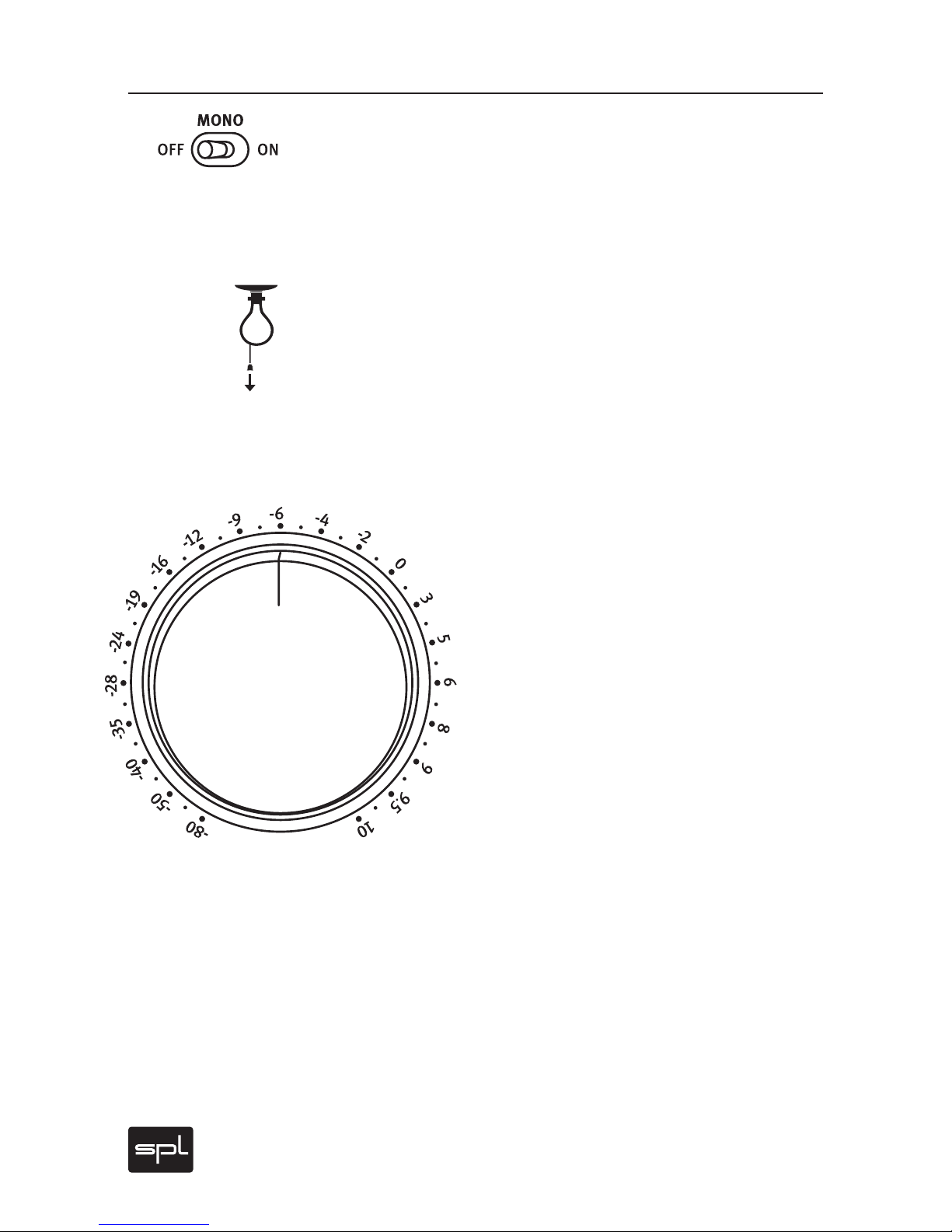
The Mono switch creates a sum of the stereo channels. If, per the above
description, you employ this Mono switch along with the Solo, the
overall signal level will be approximately 6 dB below a stereo signal
and mono-switch only. This is normal, since in Solo mode only a single
mono channel is active.
Aside from the above scenario, the Mono switch also offers important
and useful functions in combination with Phase and Solo switches in its
ability to examine the mono compatibility of a mix. While such compatibility tests are essentially the same as in earlier eras, they nonetheless
remain an important standard in radio mixing or vinyl production.
Volume
The Volume level control allows you to increase or decrease the
signal level at the headphone output from between +10dB
down to -80dB.
To this end we employ a high-grade ALPS RK27 poten-
tiometer. It distinguishes itself through a high head-
room, very low tolerance and excellent handling
that on the one hand offers sufficient resistance
while, on the other, avoids stickiness.
The Volume control is calibrated in a relative dB
scale that references the input level. The 2-o’clock
position represents 0 dB, where the input signal
is led to the output with an unaltered level (unity
gain).
If a 600 Ohms headphone is connected, a 0 dB Volume
control setting results in ca. 80 dB sound pressure level,
measured at a distance of 3 cm from a headphone transducer.
With a stereo signal the sound pressure level is then at ca. 83 dB.
Mono, Volume
V
O
L
U
M
E
Page 25

Phonitor
25
Quick Guide To Headphone Monitoring
Operation
Adjust Headphone Reproduction
To Loudspeaker Monitoring
The Phonitor offers foremost a complete set of options required for
professional monitoring: Solo L/R, Phase Reverse L/R, Mono, Dim,
Volume, VU & PPM Metering.
In addition, new functions such as Crossfeed, Speaker Angle and
Center Level transform the Phonitor from a traditional headphone amplifier into a headphone monitoring amplifier, with which it is possible
to achieve reproduction equivalent to studio monitors.
However, these new functions also require that you take some time
and acquaint yourself with these functions.
We recommend proceeding with the following five steps:
1. Initially choose your audio material from sources you know well, and
in a first production, that which is similar to what you wish to mix. It
is not sensible to listen to classic music while planning a Phonitor
setup to mix a pop production. Classic music stereophony recording involves a much more restricted stereo width than pop or rock
music, where artificial “panorama stereophony“ often provides for a
much broader imaging. Compare and match the volume of speakers
and headphones.
2. Note that you should be able to switch quickly and smoothly be-
tween speaker and headphones when making comparison tests. It
is also important that you can switch off the loudspeakers quickly
to avoid crosstalk into the headphone. The degree of loudspeaker
crosstalk into the headphones will of course depend on whether you
have open, half -open or closed headphones.
3. As starting points, first choose the following adjustments:
Crossfeed: 3, Speaker Angle: 30°, Center Level: -1,2dB.
4. Activate CROS./SPK. and CENTER (switches to the On position). The
audio channels will now be mixed with time, level and frequency corrections calculated precisely to match what you hear when monitoring over loudspeakers. >
Page 26
26
Phonitor
QUICK GUIDE To Monitoring Functions
Operation
You should now compare what you hear with headphones and loud-
speakers. First, whether or not you have the correct width in your
stereo image. If this appears too narrow or too broad with the headphone, you have always two ways for further adjustments:
A. Increase Crossfeed. With this approach more of each channel is
mixed to the opposing side, but the Speaker Angle remains unaffected. Technically speaking, this process changes the interaural level
difference. However, the interaural time difference on the contrary
changes only minimally.
B. Alternatively you can keep the Crossfeed adjustment identical
(thus keeping the interaural level difference), but for example increase the Speaker Angle. This way the interaural time difference is
increased, which in turn has the effect of a broader image. The interaural level difference is only slightly altered. Do not be misled by the
scaled Speaker Angle degree numbers so that you think you need to
follow only those exact values given for your loudspeakers. These
values are to be considered as approximations for the determination
of interaural time differences. In an individual installation, a loudspeaker pair set up at a 30° angle may in fact be perfectly represented with a 40° Speaker Angle switch adjustment at the Phonitor.
Tip
If you are uncertain about the angle your loudspeakers are set up, you
can calculate this as follows: You‘ll need a pocket calculator with pi
functions (in this case ‚arctan‘ = arc tangens) and a measuring tape.
Measure the distance between both loudspeakers, that is, between
the cone midpoints, and divide the distance by 2. We call this result A.
Now measure the distance between the loudspeaker centers and the
location of your ears at the listening position. This result we call B. The
angle W, in which the loudspeakers are set up is calculated according
to the formula: W = arctan A:B.
Page 27

Phonitor
27
QUICK GUIDE To Monitoring Functions
Operation
5. After you have set up Crossfeed and Speaker Angle, you can then determine your Center Level setting. Although at normal hearing levels
over headphones the center signal generally seems too quiet, after
Crossfeed and Speaker Angle processing it then can seem too loud.
Therefore the center level can be lowered to avoid this effect.
After finishing these adjustment you should have achieved a very good
initial headphone equivalent of your loudspeaker reproduction.
But as a final bit of advice we‘d like to emphasize that monitoring
over loudspeakers remains important. Every studio offers alternative monitoring with distinctive sounds (near field, mid field and full
range). Experienced engineers hear a mix on the portable radio, in the
car and through a Hi-fi setup. And everywhere a mix will sound different – just as it will over headphones. But for mixing, the Phonitor gives
results with headphones that are as close to (near field) monitoring as
possible.
Page 28

28
Phonitor
Specications
Audio
Frequency Response: ‹10 Hz to ›200 kHz (-3dB)
CMR: -80 dBu
@ 1 kHz, 0dBu input level and unity gain
Crosstalk @ 1 kHz: -67 dB
THD @ 1 kHz: 0,005 %
@ 0dBu input level and unity gain
Noise (A-weighted): -97 dBu
Dynamic Range: 129,5 dB
@ connection with 600 Ω Impedance
Inputs (XLR connections, electronically balanced)
Impedance: ca. 20 kΩ balanced
ca. 10 kΩ unbalanced
Maximum Input Level: +24 dBu
Outputs
XLR Connections: Input thru, electronically balanced
Headphone Output: 6,3 mm stereo TRS connection
Pin Wiring Tip = left, Ring = right, Shaft = GND
Impedance: 9 Ω
Power Amplier
Max. Output Performance: 1,7 W (+32,2 dBm)
@ 1 kHz and 600 Ω connection
360 mW (+25,6 dBm)
@ 1 kHz and 30 Ω connection
Display Elements
VU Meter: Input levels from -20 dB to +5 dB
Signal LED: Input signals from -22 dBu
Overload LED: Displays input overload from +21 dBu
Power Supply
Voltages: 230 V AC, 50 Hz/120 V AC, 60 Hz
Power Consumption: max 23,7 VA
Fuses (slow blow): 200-240 V AC: 500 mA/100-120 V AC: 1 A
Dimensions & Weight
H x W x D (mm): 106 x 216 x 393 (H w/o Feet 88 mm/2U)
Weight: 4,05 kg
0 dBu = 0,775 V. Subject to change without notice.
Page 29
Phonitor
29
Measurements
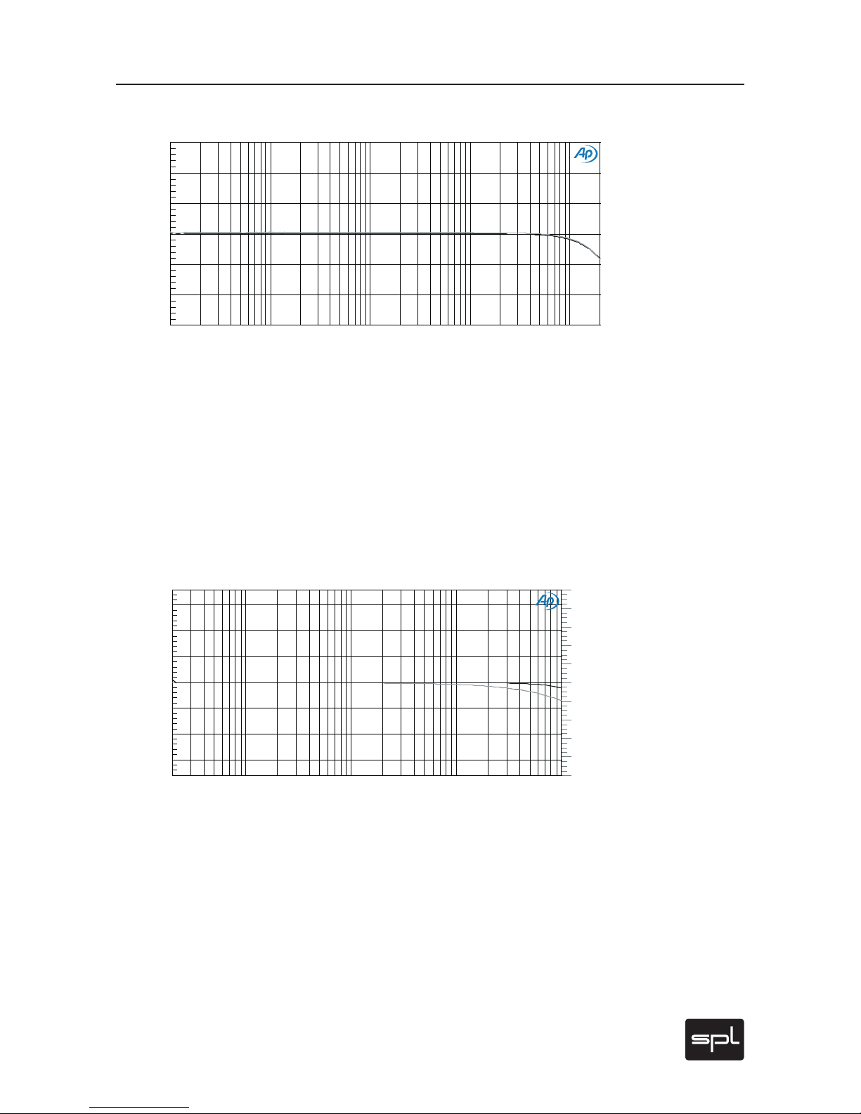
Frequency Response Input/Headphone Output, Lef t and Right Channel
Measuring output and input 600 Ohm, Volume control Phonitor 0 dB:
‹10 Hz to ›200 kHz (-3dB).
The large Frequency response range excludes that the frequency spectrum is limited at any point. Transmission of formants and octaves of an
instrument’s sounds can not be narrowed.
Phase Response Input vs. Output, Left and Right Channel
Measuring output and input 600 Ohm, Volume control Phonitor 0 dB.
This measurement shows the minimum deviation of phase in the upper
frequency range. Phase response describes the time difference between input and output signal – the less, the better. The extremely
tight phase response up to 50 kHz excludes any audible effects.
Audio Precision 05/27/08 09:50:42Phonitor Model 2730
-3
+3
-2
-1
+0
+1
+2
d
B
u
10 200k20 50 100 200 500 1k 2k 5k 10k 20k 50k
Hz
Audio Precision 04/15/08 08:34:58Phonitor Phase/FC
-10
+10
-8
-6
-4
-2
+0
+2
+4
+6
+8
d
B
u
-150
+150
-100
-50
+0
+50
+100
d
e
g
20 100k50 100 200 500 1k 2k 5k 10k 20k 50k
Hz
Page 30
30
Phonitor
Measurements
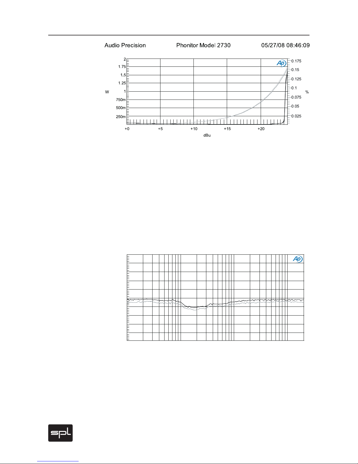
THD vs. Output Level (W)
Measuring output and input 600 Ohm, Volume control Phonitor 0 dB.
This measurement represents an analysis of THD values over the complete output level range. High THD values can be perceived as rough
sounds and overemphasized highs. In usual operating ranges around
0 dBu, the Phonitor‘s THD values are extremely low. With a 0 dB input
signal and 600 Ohm headphones the SPL is at ca. 83 dB (stereo signal
in 3 cm distance). Volumes that would result from 10 dBu are already far
above healthy levels.
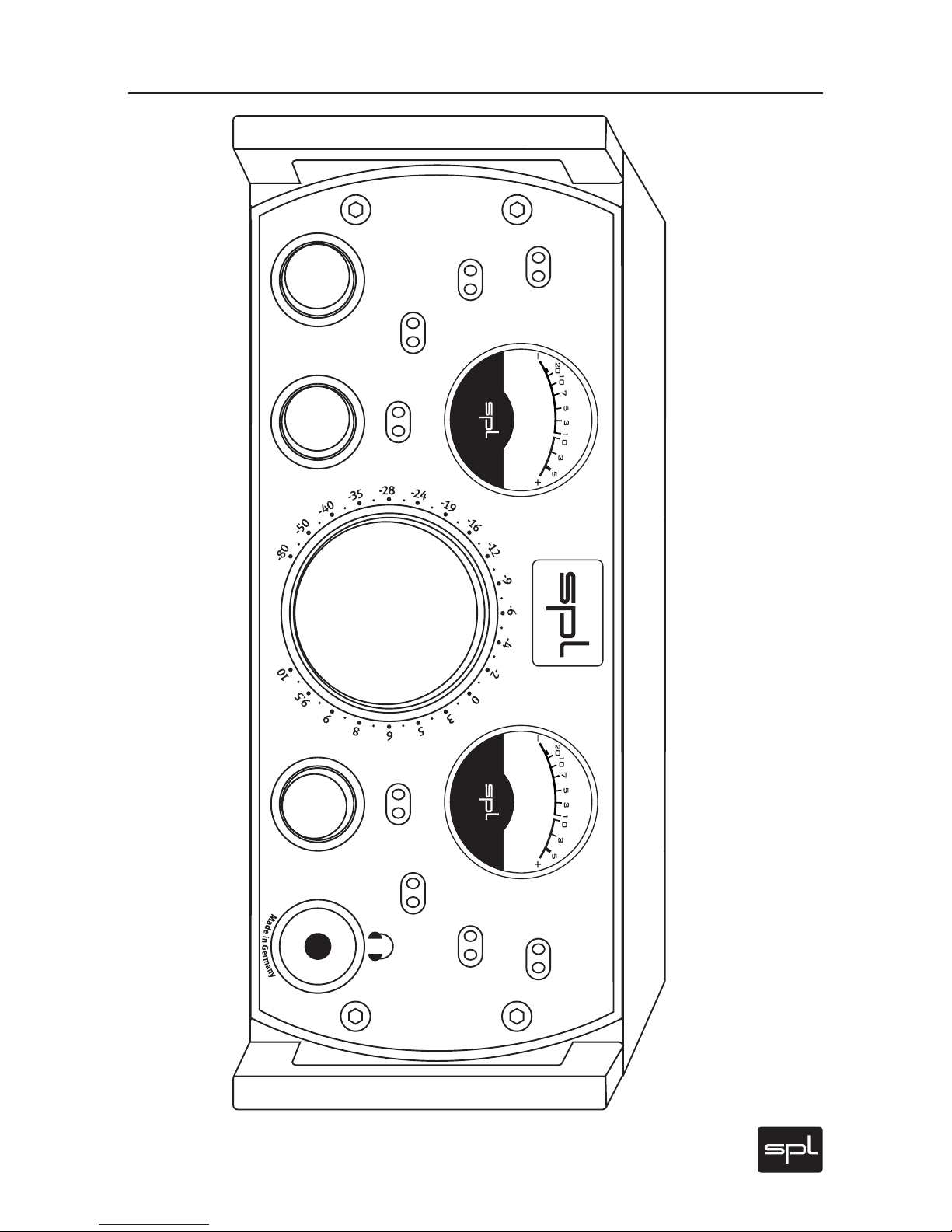
THD vs. Frequency
Measuring output and input 600 Ohm, Volume control Phonitor 0 dB.
THD vs. frequency range from 10 to 20 kHz at 0 dB over both channels.
The values are extremely low below 0.005% throughout the whole
range; even in long sessions this ensures listening without ear fatigue.
Audio Precision 05/27/08 10:22:37Phonitor Model 2730 THD+N ratio
0.001
0.01
0.002
0.003
0.004
0.005
0.006
0.007
0.008
0.009
%
10 20k20 50 100 200 500 1k 2k 5k 10k
Hz
Page 31
Phonitor
31
Copy Master: Recall Settings
1
5
°
2
2
°
3
0
°
4
0
°
5
5
°
7
5
°
-
2
.
0
-
1
.
6
-
1
.
2
-
0
.
9
-
0
.
6
-
0
.
3
d
B
C
E
N
T
E
R
L
E
V
E
L
OFF
ON
OFF
ON
METER CAL.
METER MODE
VU PPM
+60
-20
MONO
CROS./SPK. CENTER
OFF ON OFF
SOLO
L R
OFF
Ø
L R
OFF
S
P
E
A
K
E
R
A
N
G
L
E
C
R
O
S
S
F
E
E
D
M
I
N
2
3
4
5
M
A
X
DIM
120 V Rail Headphone
Monitoring Amplifier
Phonitor
Model 27 30
V
O
L
U
M
E
Page 32

32
Phonitor
All SPL products come with a two-year manufacturer’s guarantee
against defects in material or assembly from the date of purchase. End
users are supported in the two-year guarantee through their distributor or dealer. In such cases, please contact your dealer for full guarantee conditions and service.
Direct SPL product support requires product registration. Please fill
out the guarantee card enclosed in the package legibly in printed letters and send it directly to SPL. Or use the online registration form that
may be reached at www.soundperformancelab.com (international clients) or www.spl-usa.com (US clients).
Guarantee, Product Registration
Guarantee
 Loading...