

Page 1
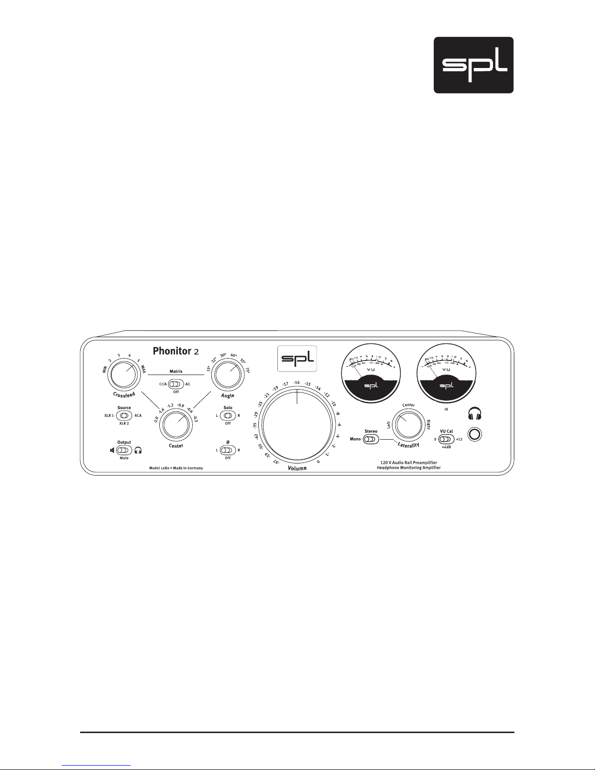
Manual
Phonitor 2
120 Volt Amplifier for Headphones, Active Speakers and Power Amps
Models 1280/1281
Version 2.2 – 03 /2016
Page 2
2
Phonitor 2
Manual Phonitor 2
Models 1280 (black) & 1281 (silver)
Version 2.2– 03 /2016
Developer: Bastian Neu
This manual contains a description of the product SPL Phonitor 2,
Model 1280. In no way it represents a guarantee of particular characteristics or results of use. The information in this document has been ca-
refully compiled and veried and, unless otherwise stated or agreed
upon, correctly describes the product at the time of packaging with
this document.
Sound Performance Lab (SPL) continuously strives to improve its products and reserves the right to modify the product described in this
manual at any time without prior notice. This document is the proper ty
of SPL and may not be copied or reproduced in any manner, in part or
fully, without prior authorization by SPL.
Declaration of CE Conformity
The construction of this unit is in compliance with the standards and regulations of the European Community.
Notes on Environmental Protection
At the end of its operating life, this product must not be disposed of with regular household waste but must be returned to a collection point for the recycling of electrical and
electronic equipment. The wheelie bin symbol on the product, user‘s
manual and packaging indicates that. The materials can be reused in
accordance with their markings. Through reuse, recycling of raw materials, or other forms of recycling of old products, you are making an important contribution to the protection of our environment. Your local
administrative office can advise you of the responsible waste disposal
point.
WEEE Registration: 973 349 88
Contact
SPL electronics GmbH
Sohlweg 80, 41372 Niederkruechten, Germany
Phone +49 (0)2163 983 40
Fax +49 (0)2163 983 420
E-Mail: [email protected]
Internet: spl.info
Page 3

Phonitor 2
3
Content
Symbols and Notes, Scope of Delivery 4
Important Security Advices 5
Hook Up 7
Introduction 8
Phonitor, The New Heart Of Music Playback: Phonitor 2 8
Remote Control 9
Home Listening, Sound Engineers, 120 Volt Technology 10
Special Features, Applications 11
Phonitoring: With And Without Magnifiers, The End Of Ear Fatigue 12
Tech Talk 14
120 Volt operating voltage and its effects 14
Rear Panel: Power 15
Voltage Select, Power Connection, On/Off Switch 15
Rear Panel: Wiring 16
Rear Panel: Signals & Remote Control 17
Signal Connections, XLR Sockets 17
Connecting XLR to other socket formats 17
Learn Button: Learn a remote control 17
Bottom: DIP Switches 18
Output level adjustment, Phonitor 2 Insert Loop 18
Front Panel: Connection 19
Headphone Connection, Recommendations, Warning 19
Control Elements 20
Crossfeed, Angle 20
Interaural Level and Time Differences as Related to Crossfeed 21
Interaural Level and Time Differences as Related to Angle 22
Crossfeed and Angle Parameters 23
Source, Output, CRr/A, Off, All; Center 24
VU Meter, VU Cal., Solo 25
Phase ø, Stereo and Mono 26
Laterality, Volume 27
Operation 28
Adjust Headphone Reproduction To Loudspeaker Monitoring 28
Specifications 30
Measurements 31
Copy Master: Recall Sheet 33
Page 4
4
Phonitor 2
Symbols and Notes
Scope of Delivery
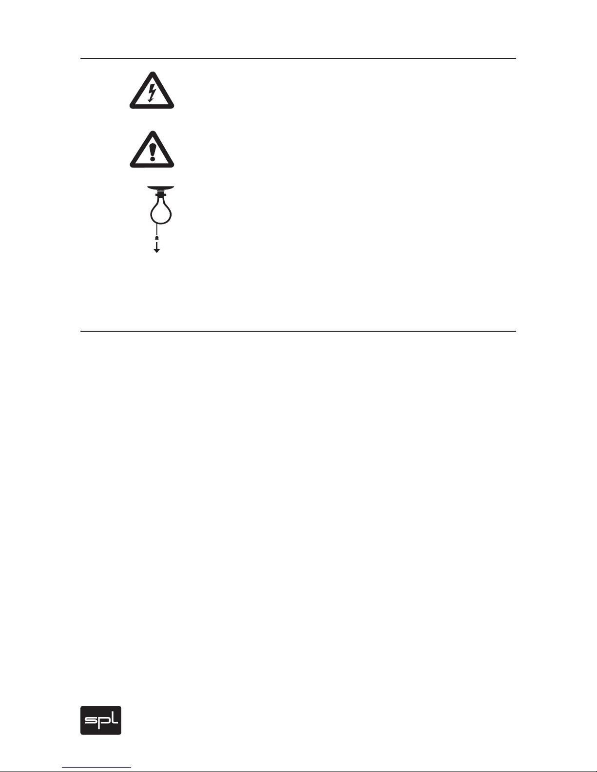
IN THIS MANUAL A LIGHTNING SYMBOL WITHIN A TRIANGLE WARNS
YOU ABOUT THE POTENTIAL FOR DANGEROUS ELECTRICAL SHOCKS
– WHICH CAN ALSO OCCUR EVEN AFTER THE DEVICE HAS BEEN
DISCONNECTED FROM A POWER SOURCE.
AN EXCLAMATION MARK (!) WITHIN A TRIANGLE IS INTENDED TO MAKE
YOU AWARE OF IMPORTANT OPERATIONAL ADVICE AND/OR WARNINGS
THAT MUST BE FOLLOWED. BE ESPECIALLY ATTENTIVE TO THESE AND
ALWAYS FOLLOW THE ADVICE THEY GIVE.
The symbol of a lamp directs your attention to explanations of important functions or applications.
Attention: Do not attempt any alterations to this device without the
approval or supervision of SPL electronics GmbH. Doing so could
void completely any and all of your warranty rights and claims to user
support.
• Phonitor 2, Model 1280
• This manual and the guarantee card
• Power cord
Page 5
Phonitor 2
5
Important Security Advices
Please read and keep this manual. You should carefully follow all of
the safety and operating instructions before you use the device.
Please also note all warnings and special safety instructions noted in
this manual and on the unit.
Connections: Only use the connections as described. Other connections can lead to health risks and damage the equipment.
Water and humidity: Do not use this device anywhere near water (for
example in a bath room, a damp cellar, near swimming pools, or similar environments). Otherwise your are dealing with an extremely high
risk of fatal electrical shocks!
Insertion of objects or fluids: Be careful to not insert any object into
any of the chassis openings. You can otherwise easily come into contact with dangerous voltage or cause a damaging short circuit. Never
allow any fluids to be spilled or sprayed on the device. Such actions
can lead to dangerous electrical shocks or fire!
Opening the unit: Simply put: DON‘T, if you are not a certified SPL technician or engineer.Really: Do not open the device housing, as there is
great risk you will damage the device, or – even after being disconnected – you may receive a dangerous electrical shock!
Electrical power: Operate the device only from power sources that can
provide proper power. When in doubt about a source, contact your
dealer or a professional electrician. To be certain you have isolated
the device, disconnect all power and signal connections. Make sure
that the power supply plug is always accessible. When not using the
device for a longer period, make sure to unplug it from your wall power
socket.
Cord protection: Make sure that your power and audio signal cords are
arranged to avoid being stepped on or any kind of crimping and damage related to such event. Do not allow any equipment or furniture to
crimp the cords.
Power connection overloads: Avoid any kind of overload in connections to wall sockets, extension or splitter power cords, or signal inputs. Always keep manufacturer warnings and instructions in mind.
Overloads create fire hazards and risk of dangerous shocks! >
Page 6

6
Phonitor 2
Lightning: Before thunderstorms or other severe weather, disconnect
the device from wall power; do not do this during a storm in order to
avoid life threatening lightning strikes. Similarly, before any severe
weather, disconnect all the power connections of other devices and
antenna and phone/network cables which may be interconnected so
that no lightning damage or overload results from such secondar y
connections.
Air ventilation: Chassis openings offer ventilation and serve to protect the device from overheating. Never cover or otherwise close off
these openings. Never place the device on a soft surface (carpet, sofa,
etc.). Make sure to provide for a mounting space of 4-5 cm/2 inches
to the sides and top of the unit when mounting the unit in racks or on
cabinets.
Controls and switches: Operate the controls and switches only as described in the manual. Incorrect adjustments outside safe parameters
can lead to damage and unnecessary repair costs. Never use the switches or level controls to effect excessive or extreme changes.
Repairs: Unplug the unit from all power and signal connections and
immediately contact a qualified technician when you think repairs are
needed – or when moisture or foreign objects may accidentally have
reached inside the housing, or in cases when the device may have fallen and shows any sign of having been damaged. This also applies to
any situation in which the unit has not been subjected to any of these
unusual circumstances but still is not functioning normally or its performance is substantially altered. In cases of damage to the power
supply and cord, first consider turning off the main circuit breaker before unplugging the power cord.
Replacement/substitute parts: Be sure that any service technician
uses original replacement parts or those with identical specifications
as the originals. Incorrectly substituted parts can lead to fire, electrical shock or other dangers, including further equipment damage.
Safety inspection: Be sure always to ask a service technician to conduct
a thorough safety check and ensure that the state of the repaired device
is in all respects up to factory standards.
Cleaning: Do not use any solvents, as these can damage the chassis
nish. Use a clean, dry cloth (if necessary, with an acid-free cleaning
oil). Disconnect the device from your power source before cleaning.
Important Security Advices
Page 7
Phonitor 2
7
Be very careful to check that the rear chassis power selection is set
correctly before using the unit (230 V position: 220-240 V/50 Hz, 115 V
position: 110-120 V/60 Hz)! When in doubt about a source, contact
your dealer or a professional electrician.
Read page 15 for instructions on how to set the correct voltage.
Before connecting any equipment make sure that any machine to be
connected is turned off. Follow all safety instructions from page 5.
Place the unit on a level and stable surface. The unit’s enclosure is EMC-safe and effectively shielded against HF interference.
Nonetheless, you should carefully consider where you place the
unit to avoid electrical disturbances. It should be positioned so that
you can easily reach it, but there are other considerations. Try not to
place it near heat sources or in direct sunlight, and avoid exposure to
vibrations, dust, heat, cold or moisture. It should also be kept away
from transformers, motors, power amplifiers and digital processors.
Always ensure sufficient air circulation by keeping a distance of 4-5
cm/2 inches to other units and to the sides of the unit.
Before You Begin
Make sure the Volume control is turned hard left before you power up
the unit. Now control Volume. Note that too high levels can damage
headphones and hearing!
Hook Up
Page 8

8
Phonitor 2
Introduction
Phonitor
When we brought out the first Phonitor — the first ever headphone
amp with 120 Volt technology — back in 2008, the professional audio
world seemed to have been eagerly awaiting it. The success of this
unique headphone preamp was overwhelming. In hindsight, we also
had to wonder how none of us had come to the idea of combining basic
monitoring options, speaker simulation capabilities and a headphone
preamp. Ever since we call this new species a „Headphone Monitoring
Amp,“ which inspired the product name itself: Phonitor.
Interestingly enough, the Phonitor not only became best friends with
thousand of professional users, it also won a lot of fans in the Hi-Fi
market segment. But that was by no means a coincidence — ultimately, the Phonitor can be counted among the best headphone preamps
in the world thanks to our unique 120-volt technology. With its exceptional technical specifications and a huge power margin, it can reproduce any musical material without the slightest modification, since
signal processing is not limited and, thus, signals are not altered at all.
Music sounds more natural and hearing fatigue is drastically reduced.
Given all that, it was easy to understand the enthusiasm with which
musicians, sound engineers and music lovers received the Phonitor
worldwide.
The New Heart Of Music Playback: Phonitor 2
Many Phonitor users told us they wished they could also use the unmatched signal quality that the Phonitor provides to feed their speakers. And so began to take form the idea of making its successor a
full-fledged stereo preamp that could become the hear t of modern
professional and home systems alike where headphones have a preeminent importance. Moreover, we have achieved enormous advances with our 120-volt circuits, making the technical specifications of the
Phonitor 2 a new standard in all respects: 141dB dynamic range, 107dB
signal-to-noise ratio (A-weighted in both cases), -112/-114dB THD
(headphone/speaker output with +30dBu output level). Mind you, the
THD measurements define the limits of the measuring equipment but
not those of the Phonitor 2.
Other improvements concern specially the operation of virtually all
headphone types and impedances: the Phonitor 2 works seamlessly
with low-impedance headphones with load impedances as low as 10
Ohm (40 ohms with balanced headphones).
Page 9

Phonitor 2
9
The Two Sides Of The 120 Volt Amp
As always, the Phonitor 2 remains first and foremost a headphone preamp, which is easy to identify given the elaborated loudspeaker-like
reproduction with headphones. Considering that the 120-volt amp
provides everything needed to preamplify, manage and control the
volume of line level signals, the latter are now also available at the
output on the rear panel.
Besides headphones, it is now possible to connect active loudspeakers and power amps directly at the output. If there is the need for
more than one stereo speaker set, it is recommended to use a passive
distribution module. It is important to know that all controls can be
used for both outputs with headphones and loudspeakers. Obviously,
loudspeaker simulation makes no sense when using real loudspeakers. However, owners of electrostatic headphones could connect their
headphones to the output and use the simulation feature as well.
Likewise, all monitoring options (phase reverse, solo, mono, mute)
can be selected for both outputs, so that the Phonitor 2 can be used as
Monitor Controller for up to three different sources.
Remote Control
The volume can be controlled remotely. Naturally, the audio signal is
controlled via a high-quality motor potentiometer in that case. In comparison, electronic adjusting with or without AD/DA converter – very
common these days – would have a significant influence on the signal
quality.
To control it you can use any IR remote control: the remote must not
learn the Phonitor 2, but rather the Phonitor 2 learns to understand
your remote’s signal (see page 17).
Introduction
Page 10

10
Phonitor 2
Introduction
Home Listening
Home users can enjoy a central control unit for modern music playback of stereo signals that supports all known formats – and that with
an unheard-of price/performance ratio. As such, the Phonitor 2 does
justice to its central position. It is comforting to know that there is no
need to fear a sound bottleneck limiting your system in such a critical
spot in the chain.
The Phonitor 2 matches perfectly modern playback concepts: minimalist chains with active speakers and almost any pair of headphones
can be centrally fed via three different paths, thanks to an integrated
high-quality amplifying and signal-managing concept.
Sound Engineers
Besides being a reference-quality Monitor Controller, the Phonitor 2,
together with a carefully matched pair of headphones, offers professional users an excellent monitoring alternative to their main speakers. The audio quality and features of the Phonitor 2 provide the best
conditions to work effectively without hearing fatigue.
120 Volt Technology
The foundations of this high-end-development is our 120 Volt reference technology: specially developed and manufactured op-amps
that run on an operating voltage of 120 volts, which corresponds to
approximately twice that of most modern analog audio semiconductor
technologies. Thanks to our 120-volt circuitr y and processing we reach
outstanding performance levels, especially in terms of dynamic range
and headroom. As such, the technical specifications of the Phonitor 2
exceed all known analog and digital standards (please refer to the
“End Of Ear Fatigue” chapter on page 12).
Page 11

Phonitor 2
11
Introduction
Special Features
• The Reference – the Phonitor 2 sets new technical and sound
standards.
• For loudspeakers and headphones – two-channel 120 Volt amp for
headphones and active loudspeakers or power amps
• For all types of headphones – dynamic, balanced, electrostatic
• Optimally suited for low-impedance headphones starting from
10 ohms (40 ohms for balanced headphones)
• Remote volume control with motor potentiometer
• High-resolution laterality correction compensates right/left volume
differences.
• Switchable level adjustment (consumer to professional level, 1:1,
+6dB, +12 dB)
Applications
• Stereo preamplification and headphone amplification for three
sources
• High-quality music playback at home
• Central monitoring unit in professional environments with all classic features like phase reverse, solo, mono
• Re-Amping (for example, level boost after analog master
processing)
• Headphone amplifier for all headphone systems and impedances
• Loudspeaker-like reproduction with headphones
• Monitoring alternative in studios and mobile units
• Adjustment of headphone playback to match familiar monitor
speakers
• Mobile reproduction of usual monitoring conditions
Page 12

12
Phonitor 2
Tech Talk
Phonitoring: With And Without Magniers
Already for the headphone monitoring – or phonitoring – part alone,
the Phonitor 2 encompasses advantages of both kinds of traditional
monitoring methods: On one hand the analytical headphone monitoring is like working with an acoustic magnifier but without external
room influences; on the other hand, the loudspeaker-like reproduction with headphones allows monitoring which forgoes the microscopic effect, but provides for room ambiance.
Working with the magnifier effect of headphones has the advantage of
safely hearing clicks or similar defects and helps in fine tuning crossfades or to judge tonal problems in individual tracks. On loudspeakers such analyses are much more difficult, as such problems just are
not as apparent when one is working without being able to “zoom in”
aurally. Conversely, loudspeakers provide monitoring with the advantage of spatial balance in a (definable through placement) stereo
width, which in turn provides the illusion of an acoustic stage.
Traditional headphone reproduction produces one 180-degree stereo
width in the middle of the head, and it is exactly this which creates
the ver y problematic-to-impossible headphone mixing environment.
An essential reason for such unnatural ambiance is the complete
separation of the channels, which does not exist either in natural
hearing or in stereo loudspeaker reproduction. This makes it nearly
impossible to judge tonal balance, a stereo image and the phantom
center level. Panorama adjustments as well as related EQ settings
that one attempts with headphones, typically just do not function on
loudspeakers.
Moreover, what is often called the “super stereo effect” with headphones usually creates a great deal of ear fatigue in the long run. Over
loudspeakers the sound stage is felt in front, while in contrast, when
monitoring through headphones, the stage is present on the left and
on the right – but frontal and rear information is lost.
The End Of Ear Fatigue
Aside from these unnatural headphone ambiance there are further disadvantages with fatigue when mixing or listening with headphones.
First, some cans themselves may not be that comfortable to wear ...
Moreover, a standard headphone amplifier is often an additional important reason for premature ear fatigue. Almost without exception,
present-day headphone amplifiers employ comparatively undemanding IC’s. In the best cases they might work with symmetrical voltages
of +/-15 V to +/-18 V, and in less favorable cases, with only a simple
supply of 9 or 12 V from cheaper external “wall-wart“ power supplies.>
Page 13

Phonitor 2
13
Tech Talk
But the voltage level acts in circuitry much like the cubic inch capacity
to the productive power of a combustion engine: Cubic inch capacity
is replaceable with nothing but more cubic inch capacity – and in the
productive power of electronics, voltage level functions similarly.
For some years, now, SPL has addressed this issue in all of its mastering product series through its own specifically developed 120 volt technology. Consoles and signal processors of the SPL Mastering Series
appear as central elements in installations of today’s most renowned
mastering houses (for example Bob Ludwig’s Gateway Mastering &
DVD in the USA, Simon Heyworth’s Super Audio Mastering in Great
Britain, the Galaxy Studios in Belgium and the legendary Wisseloord
in the Netherlands). This 120 volt technology is based on discrete operation amplifiers from SPL’s own production, developed and perfected over many years by SPL’s co-founder and chief developer, Wolfgang
Neumann. These OPs work with high-performance semiconductors in
Class A technolog y at a symmetrical voltage of +/-60 V.
The Phonitor 2 is the first unit to employ the 2nd generation of our 120
Volt OPs with improved specifications once again. They have Signal To
Noise Ratio of 116 dB and offer a nearly 34 dB headroom – that yields
an unequalled 150 dB dynamic range.
The musical result is not to be mistaken: Regardless of the monitoring means, regardless of how loud you monitor – the Phonitor 2 always
remains a distant, impartial factor unaffected when used to capacity
and beyond being overloaded. The phase stability is always perfect,
its THD next to immeasurable.
The Phonitor 2’s OPs cannot be stressed in the most stressful circumstances, and for precisely this reason its musical sound is always relaxed and spacious. All frequencies are reproduced in balance, basses are stable and tight, mids are clear and differentiated and highs remain transparent and soft. Particularly striking is the fact that you can
easily listen to ever y detail. Hearing fatigue makes it usually harder to
carefully listen to and understand complex signals over a long period
of time. The Phonitor 2 reverses this situation turning it into a pleasant
listening experience that leaves you longing for more.
Such supreme and heretofore unreachable neutrality in audio reproduction is the direct consequence of our technical approach and basis
in 120 volt technology: Possible disturbances from such as noise or
distortion are so slight that we even arrive at the boundaries of the
best measuring equipment, and what remains is quite simply unalt
Page 14
14
Phonitor 2
120 Volt operating voltage and its effects
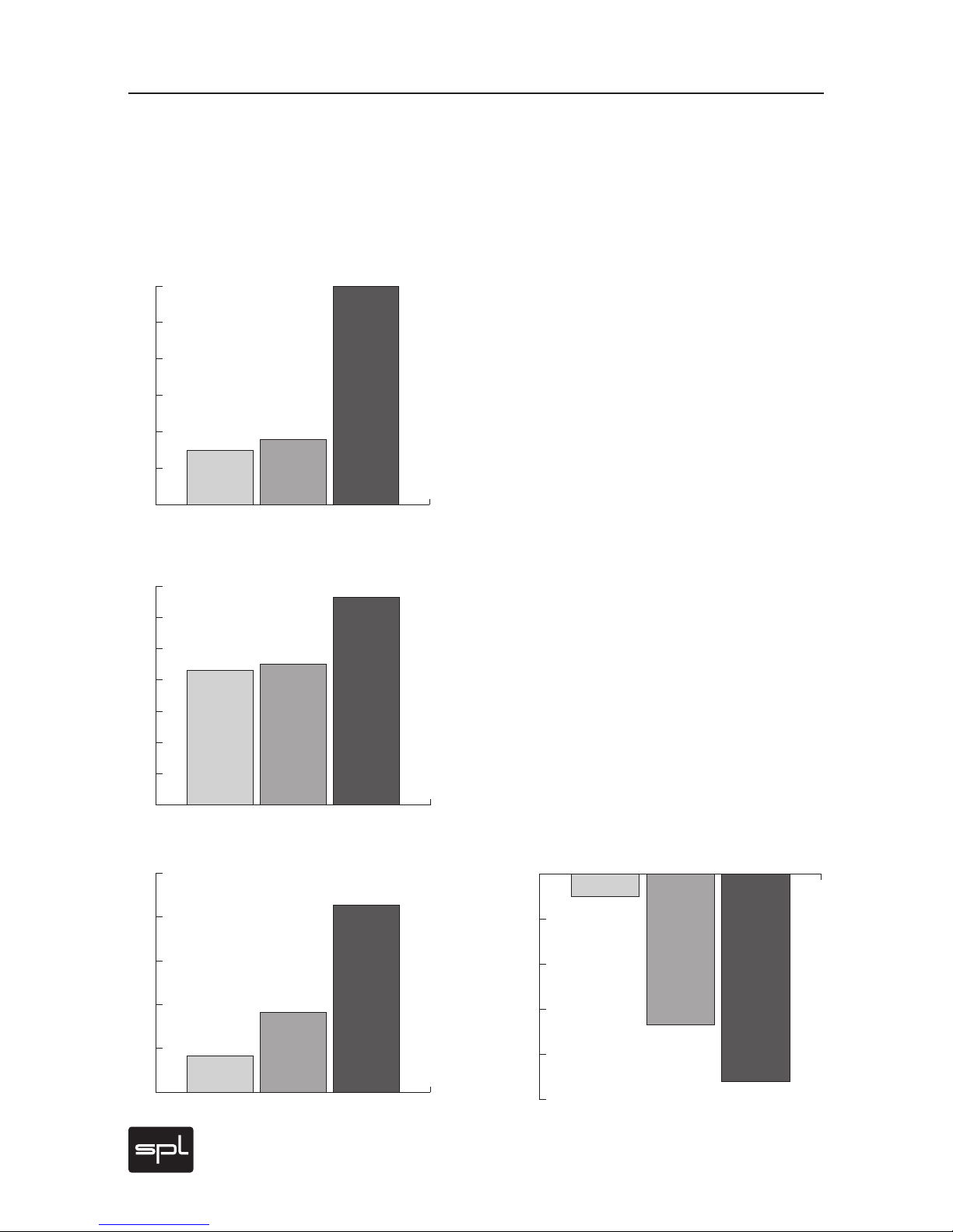
These diagrams clearly show how our 120-volt technology compares
to other circuits with a lower operating voltage. The direct relation between operating level and maximum level is fundamental for the classification: the higher the operating level, the higher the maximum level
a circuit can handle. And since virtually all essential acoustic and musical parameters depend on
this relation, a higher operating voltage also has
a positive impact on the dynamic range, distortion
limit and signal-to-noise ratio.
Do bear in mind that dB scales do not represent
linear but rather exponential increases. A 3dB
increase corresponds to doubling the acoustic
power, +6dB correspond to twice the sound pressure level, and +10dB correspond to twice the perceived loudness.
When it comes to volume, the 120-volt technology exhibits a performance, in regard to maximum
level and dynamic range, that is twice that of common components and circuits given that its values
are approximately 10dB higher.
THD measurements of the SPL op-amp show a difference of more than 3dB compared to the OPA134
at 36V — in terms of sound pressure level, that corresponds to an improvement of more than 50%.
The operating level most commonly used for audio
equipment is 30 volts.
Diagrams
Tech Talk
120
125
130
135
140
145
dBu Comparison Dynamic Range
OPA 134@30 V OPA 134@36 V SPL-OP@120 V
124,2
129,1
141,4
0
5
10
15
20
25
30
35
dBu
OPA 134@30 V OPA 134@36 V SPL-OP@120 V
21,5
22,5
33,2
Comparison Maximum Levels
0
20
40
60
80
100
120
Volt
+/- 15 Volt +/- 18 Volt +/- 60 Volt
30 V
36 V
120 V
Comparison Operational Voltages
-115
-113
-111
-109
-107
-105
dBu
TL 071@30 V OPA 134@36V SPL-OP@120 V
106
111,7
114,2
Comparison THD&N
Page 15
Phonitor 2
15
Voltage Select
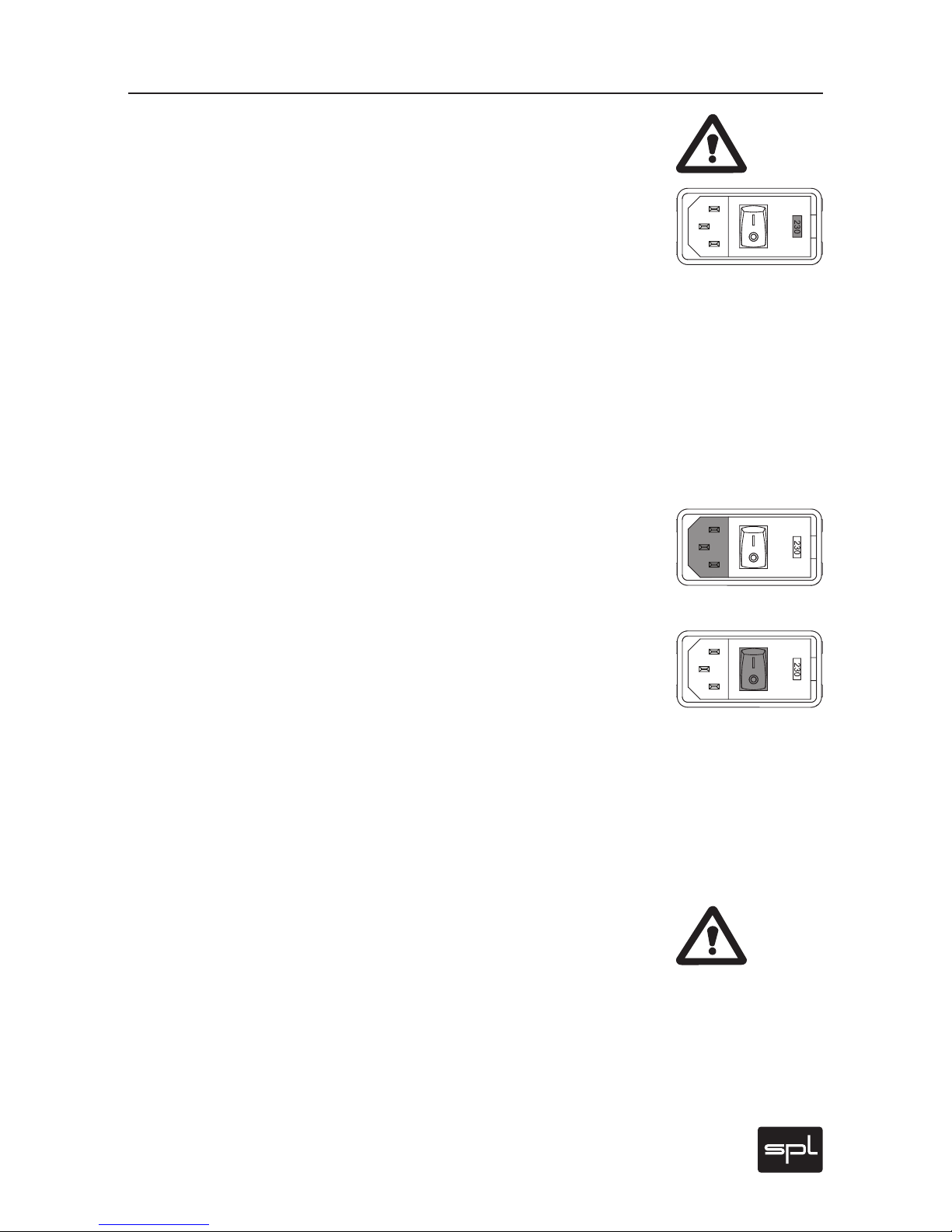
Before connecting the Phonitor 2 to the mains, make sure that the voltage selection corresponds to the values of your local power grid (230
or 115 volts).
The mains connector on the rear panel integrates a fuse box that includes fuses for both voltage ranges. To select the voltage take out
the fuse box, turn it around and place it back again. Inside the power
connector, to the right, next to the on/off switch, there is an opening
that displays the voltage selected. If the voltage indicated does not
correspond to the one required, change it by following this procedure:
Open the power connector lid with a small screwdriver (use the tiny
slots on the right hand side). Use the screwdriver to lever the red fuse
box from above until you can grab it. Take the fuse box out, turn it
around 180 degrees and place it back again. When you close the lid
again, you should see the correct voltage displayed in the opening.
Power Connection
Connect the included power cord to the rear, 3 pin power input.
The
transformer, power cord and inlet of the appliance conform to VDE, UL
and CSA requirements.
On/Off Switch
Use the rear on/off switch to activate and deactivate the unit. The operational status is indicated by the illuminated VU meters on the front
panel. We deliberately chose to place the switch on the rear panel in
order to avoid interferences from power wiring through the unit to the
front panel. When switching on and off, you do not need to follow any
particular sequence with connected devices in the periphery of the
unit. There is, however, a general rule for audio devices connected to-
gether: always turn on power ampliers last and turn them off rst. If
sufciently specied, you can also switch the unit on and off through a
multiway connector or other main switches.
Caution: Before connecting any other equipment – and in all other
cases where you are connecting cables with or from other sources –
you should be sure to switch off the Phonitor 2 and all other devices
you want to connect it to. Other wise you risk damaging the unit, other
connected gear and/or your ears.
Rear Panel: Power
Power
Page 16
16
Phonitor 2
Rear Panel: Wiring
Wiring
IR REMOTE
IR REMOTE
OUTPUT
OUTPUT
L
R
R
L
LEARN
RLRLRL
SOURCES
SOURCES
2
2
LR
1
LR
Learning Volume Up/Down:
1. Press LEARN but ton below
2. Point your remote at VUs
and press a bu tton for
VOLUM E DOWN (LEDs f lash 1x)
3. Repeat until LEDs flash 3x
4. Press a button for
VOLUM E UP (LEDs fl ash 1x)
5. Repeat until LEDs fla sh 3x
XLRs: balanced , Pin 2 = Hot (+)
For unbalanced operation
bridge Pin 3 to GND.
RCAs: Unb alanced, Tip = Hot (+)
AVIS: RISQU E DE CHOC ÉLECT RIQUE • NE PAS OUVRIR
RISK OF ELECTRIC SHOCK
DO NOT OPEN
CAUTION
Serial
Number
Made in Germany
ON BOTTOM SIDE:
DIP SWITCH WIRING
Output is DC coupled and can drive balanced
headphones (Gender changer may be required).
3
3
Phonitor
2
~ 115V AC / ~230V AC
50 Hz / 60 Hz , P max. 35 W
Fuses:
Voltage S election:
115V AC: T 1 A L 250 V
230V AC: T 50 0 mA L 250 V
1. Remove F use Holder
2. Flip O ver 3. Reinst all
1 ON: Out put +12dB
2 ON: Out put +22dB
3 ON: RCA -10d BV to +4dBu
4 ON: Sour ces 1:1 to Output
5 ON: Matr ix on rear Out put
230
1
1
2
3
1
2
3
1
2
3
1
2
3
1 2
3
1 2
3
NOTE ON XLR SOCKETS: You can establish unbalanced connections
easily and without adaptors e. g. from and to RCA sockets. In any case we
recommend readily configured cables from XLR to RCA or TS/TRS connector
to dispense with adaptors. Ask your dealer for configured cables and
forward the XLR pin wiring of the Phonitor 2 (refer to page 17).
Source 1
D/A Converter, Player
Source 2
D/A Converter, Player
Source 3
Players
Output
Aktive Speakers, Power Amps,
Balanced Headphones,
Amps for Electrostatic HP
Learn Mode for
Remote Controls
Refer to page 16
Power
Connection
Make sure that the voltage
switch setting reflects the
correct local power line voltage.
Voltage
Selector
Power
Switch
Page 17
Phonitor 2
17
Rear Panel: Signals & Remote Control
Signal Connections
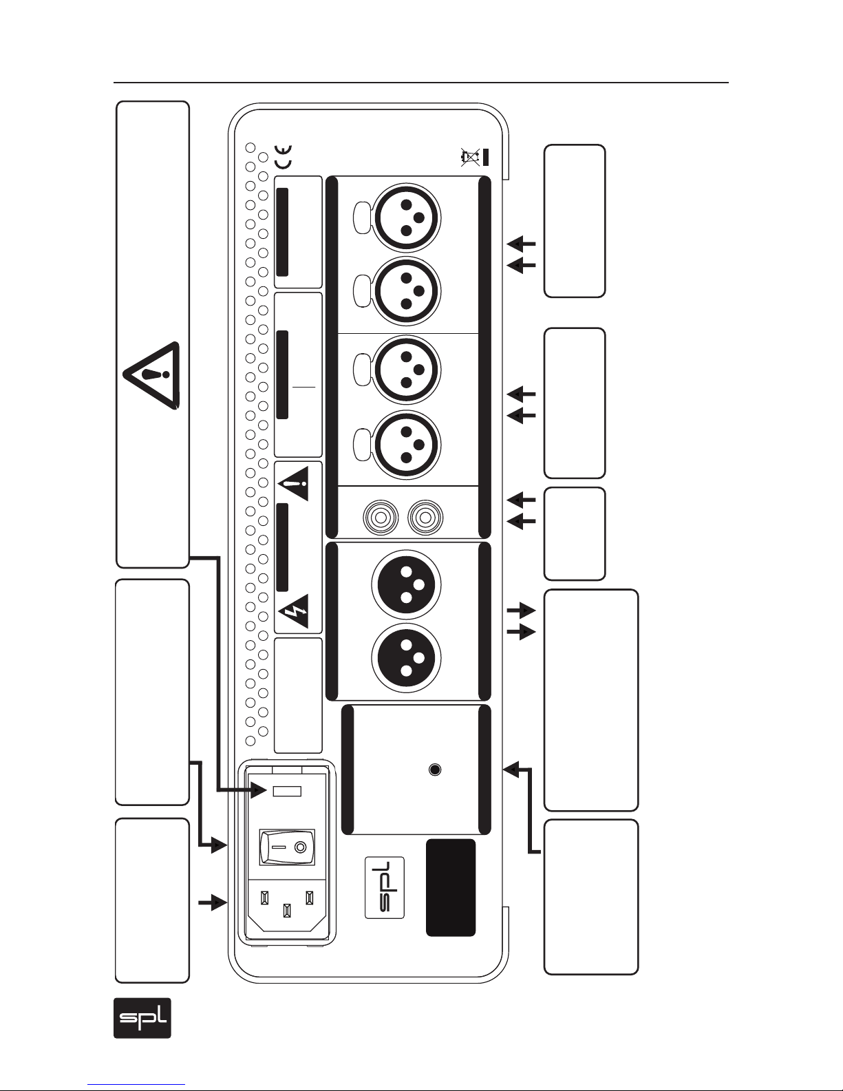
Inputs are always female and accept male connectors; outputs are
always male. All in all, a very comprehensible principle. Turn off the
unit before connecting or disconnecting any cable or equipment to it.
Otherwise you risk the possibility of damaging your ears or equipment.
XLR Sockets
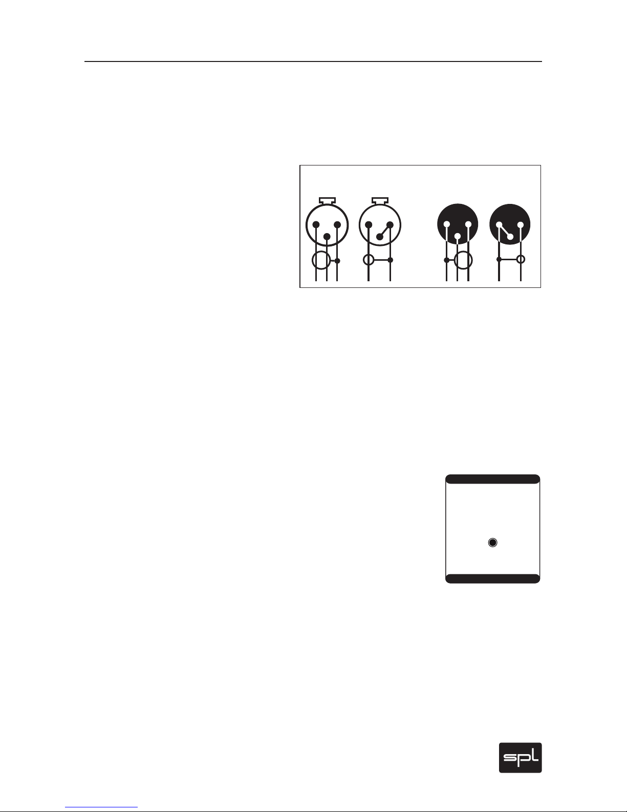
The diagram shows the pin wiring of all XLR
sockets (3 pin, balanced).
The diagram also shows how to wire the balanced XLR connections if unbalanced connections are required, for example to RCA
or TS inputs and outputs (see next section).
Connecting XLR to other socket formats
Unbalanced connections from and to RCA or 1/4" TS sockets, for example from CD players or to power amps, are no problem and can be
made without adaptors. We recommend to use individually configured
cables from XLR to RCA or TS sockets instead of adaptors. The correct
wiring is important. The diagram shows the pin configuration of the
XLR sockets and how to correctly configure them for unbalanced connections. You can get cables in any needed configuration from audio
dealers. With the diagram above, the dealer can ensure to provide the
appropriate cable for your application.
Learn Button: Learn a remote control
The volume potentiometer of the Phonitor 2 is motorized and can be
controlled with any remote control. But you must first activate the Learn
Mode in the Phonitor 2. Afterwards you must choose any two buttons on
the remote that will be used to increase or decrease the volume. Then
you simply have to save them on the Phonitor 2.
1. Press the LEARN BUTTON on the rear panel. The VU-meters light up red.
2. Point your remote towards the VU-meters and press the button you
want to use to decrease the volume. The VU-meters will light up once
every time you press a button. Press the same button repeatedly until
the VU-meters flash three times consecutively, which means the button
has been programmed.
3. Now follow the same procedure once again to program the button to
increase the volume.
Input
Output
balanced
unbalanced
balanced
unbalanced
1= GND
2=hot (+)
3=cold (-)
1
2
3
1
2
3
1
2
3
1
2
3
IR REMOTE
IR REMOTE
LEARN
Learning Volume Up/Down:
1. Press LEARN but ton below
2. Point your remote at VUs
and pres s a button for
VOLUME D OWN (LEDs f lash 1x)
3. Repeat until LEDs flash 3x
4. Press a button for
VOLUME U P (LEDs fla sh 1x)
5. Repeat until LEDs fla sh 3x
Page 18
18
Phonitor 2
Bottom: DIP Switches
Output level adjustment
The DIP switches on the bottom of the unit give you the possibility
to increase the output level in multiple steps. This is something that
ought to be considered basically in two cases: when the input level
is very low and when using high-impedance and especially powerhungry headphones.
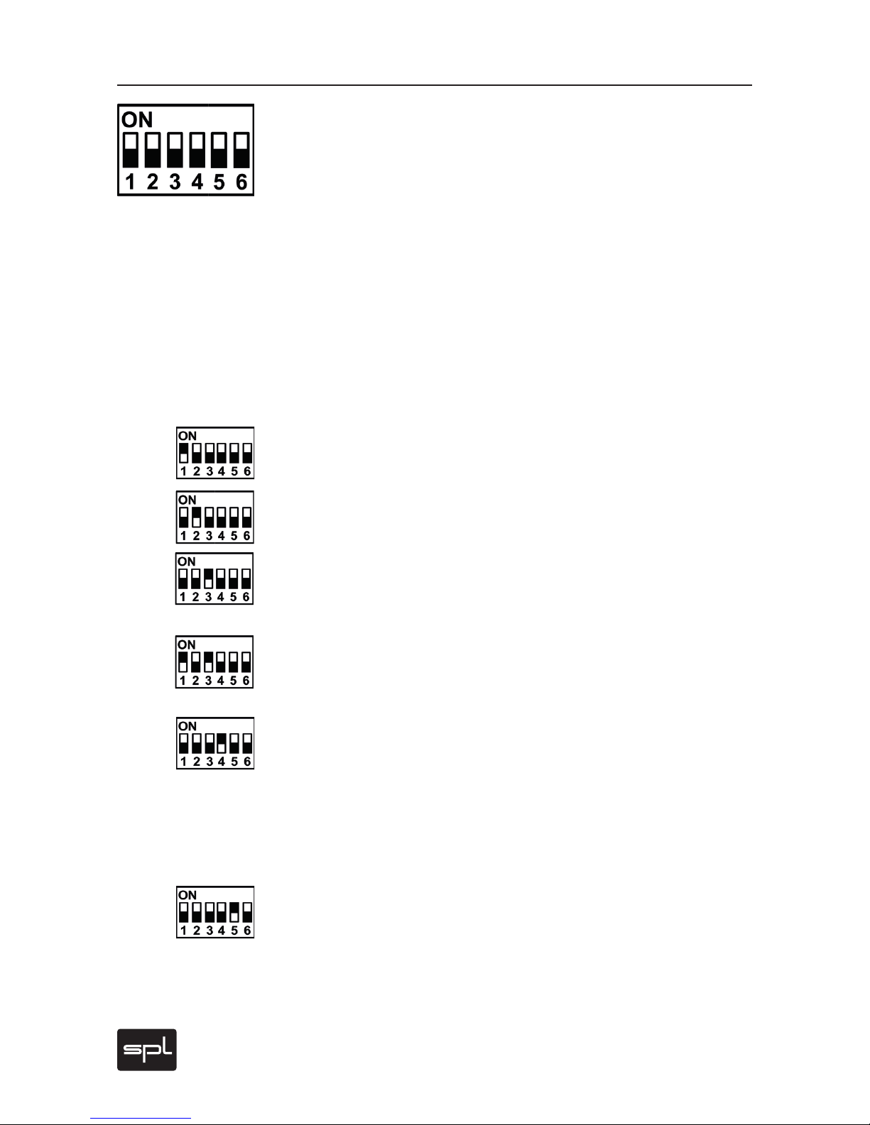
By default, the normal setting is active, all switches point down towards the numbers 1-6. The output level can be increased for all outputs in two steps: +12dB, +22dB and +24dB. Additionally, the RCA
input offers the possibility to bring the level from consumer level
(-10dBV, for CD players, for example) to professional level (0dBu).
IMPORTANT: If the level has been increased by +12dB, +22dB or
+24dB, this increment and the conversion of the RCA input to professional level will be summed (see 4.).
1. Increase of +12dB for all outputs: Switch 1 set to ON.
2. Increase of +22dB for all outputs: Switch 2 set to ON.
3. RCA input level conversion to professional level (-10dBV to 0dBu):
Switch 3 set to ON.
4. Example Summed Levels: +12dB increase for all inputs PLUS RCA
input level conversion to professional level (-10dBV to 0dBu): Switch 1
and 3 set to ON. The summing also works with Switches 2 and 3.
Phonitor 2 Insert Loop
The Inser t Loop mode for the line input is a particularity of the Phonitor
2. Switch 4 allows you to route the input signal directly to the line output without it being processed by the level or any other settings of the
Phonitor 2 (except for phase inversion). This mode is particularly interesting when you do not want to use the Phonitor 2 as a preamp or monitor controller and the source signal ought to pass through unaltered.
Matrix activation for the XLR outputs
Switch 5 activates the Phonitor Matrix for the XLR outputs of the
Phonitor2 as well.
Switch 6 has no function.
Page 19
Phonitor 2
19
Front Panel: Connection
Headphone Connection
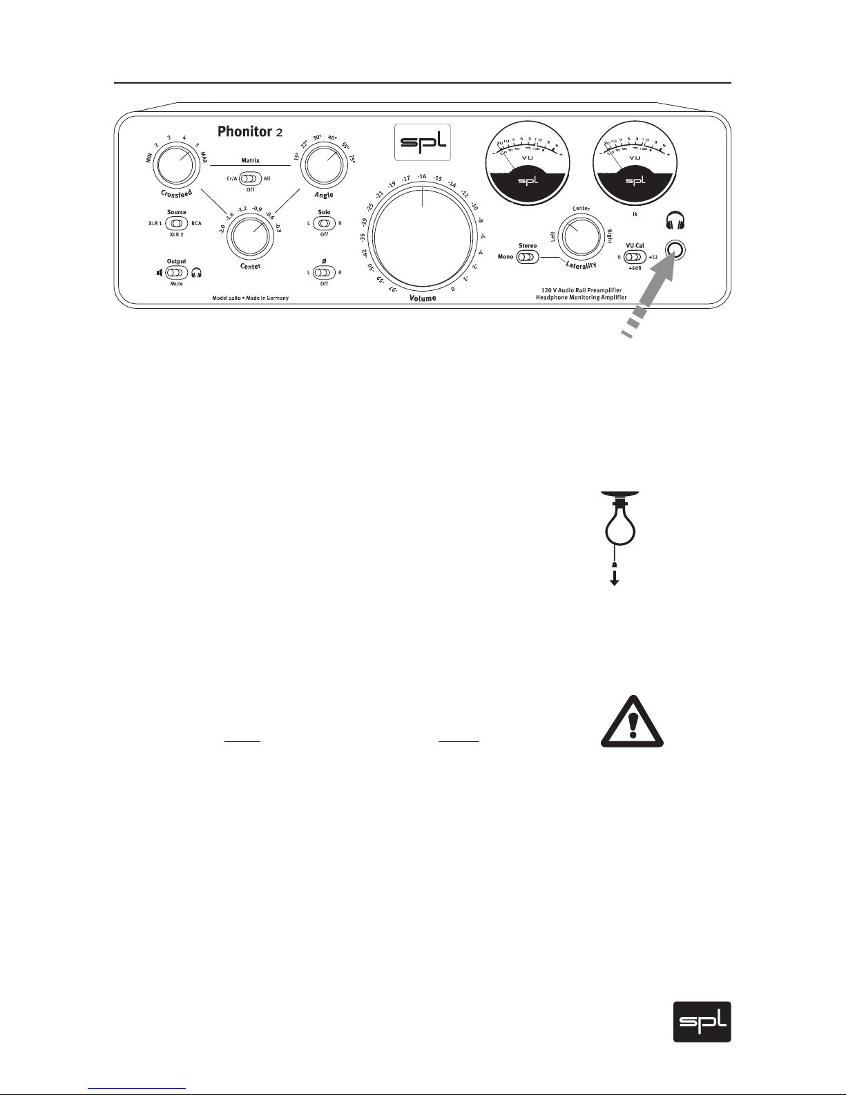
Connect headphones to the standard 1/4" (TRS) stereo plug on the
lower right front panel. The layout is: Tip =left channel, Ring = right
Channel, Sleeve = ground.
Make sure that the plug firmly seated for a solid connection.
Recommendations
Reduce volume level before you remove or plug in the headphone (or
when switching headphones). This excludes louder clicks and pops
reaching the ear. In addition, this can avoid unpleasant surprise that
follows when a headphone’s lower impedance suddenly reproduces
an otherwise acceptable Phonitor 2 volume setting of a first headphone at a much higher – even painful – level.
Warning
NEVER plug in a mono 1/4" (TS) connector to the stereo headphone
output. The use of a mono connector produces a short-circuit and destroys the final amplifier stage! Standard headphone connectors always have stereo plugs, and thus a correct connection will be assured
when you only connect headphones directly.
Page 20
20
Phonitor 2
Crossfeed
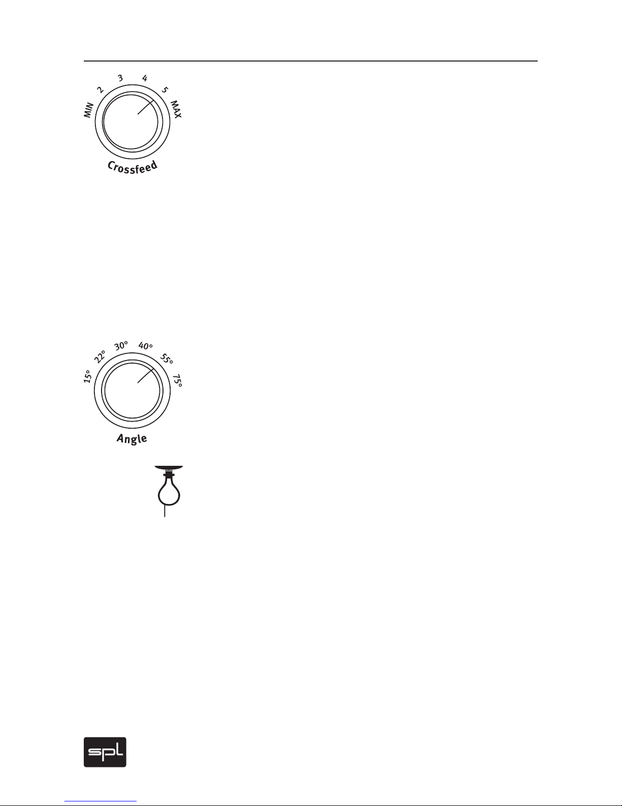
The Crossfeed switch allows you to adjust the frequency-dependent
crossfeed simulation of both channels by adjustments of interaural
level difference – as if this characteristic would be heard from monitors when in their own room ambiance. One can compare variations
in crossfeed values as approximating the influence of different room
sizes and characteristics on a given loudspeaker setup.
This adjustment can be made in six steps ranging from “minimum” to
“maximum”. Crossfeed interacts with the Angle value to simulate the
width of a stereo image (please refer to the next section).
For further information regarding simulation of a specific loudspeaker
playback setup, please refer to “Adjust Headphone Reproduction To
Loudspeaker Monitoring“ on page 26.
Angle
The Angle switch provides for frequency-dependent simulation of your
stereo image width by adjustments of interaural time difference. This
influences the moment in time at which a signal‘s wave form arrives
at the ear and corresponds to a particular variation in the angle of an
actual loudspeaker pair.
The time constants of the interaural time differences between the left
and right channels occur within a range of 90 to 635 microseconds.
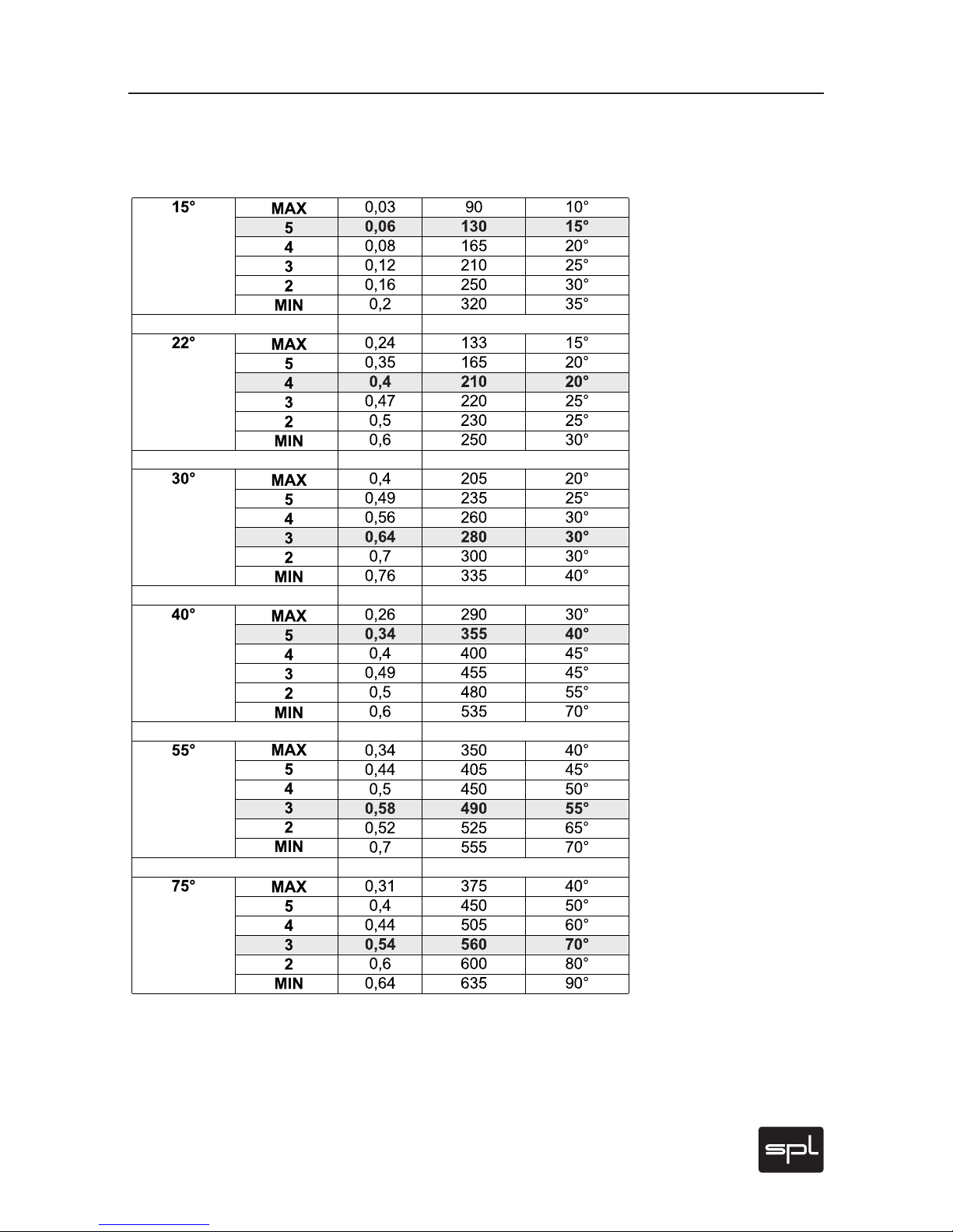
Compare the table “Crossfeed and Angle Parameters” on page 21.
We recommend to start with the figures of the accentuated lines from
this mathematically-based table for a given monitoring setup. As you
might expect, however, the best results can only occur when you follow the recommendations and then as needed, carefully engage in
your own additional fine tuning, especially between Angle and the
Crossfeed value.
For further information on the simulation of a specific loudspeaker playback, please refer to “Adjust Headphone Reproduction To
Loudspeaker Monitoring“ on page 26.
.
Control Elements
Page 21
Phonitor 2
21
Interaural Level and Time Differences as Related
to Crossfeed Setup
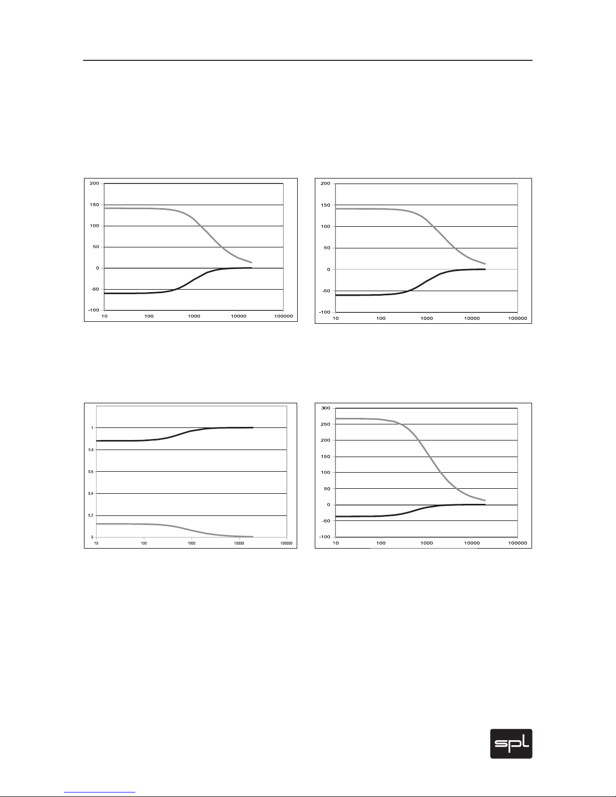
The following two diagrams show, respectively (on the left), the frequency response of interaural level differences and (on the right)
the interaural time difference at maximum Crossfeed value and at an
Angle of 30 degrees.
The following two diagrams show, respectively (on the left), the frequency response of the interaural level difference and (on the right)
the interaural time difference, at minimal Crossfeed value and an
Angle of 30 degrees.
The black curves stand for the side of the direct sound wave front,
while the gray curves stand for the opposite side. It is clearly recognizable that corrections are usually done for frequencies below 1 kHz.
You should also note that the Crossfeed control functions mainly level
dependent. Effects with respect to time differences are comparatively
slight. However, that they, too, may be altered is an indicator of interaction between Crossfeed and Angle control.
Control Elements
Page 22
22
Phonitor 2
Control Elements
Interaural Level and Time Differences as
Related to Angle Setup
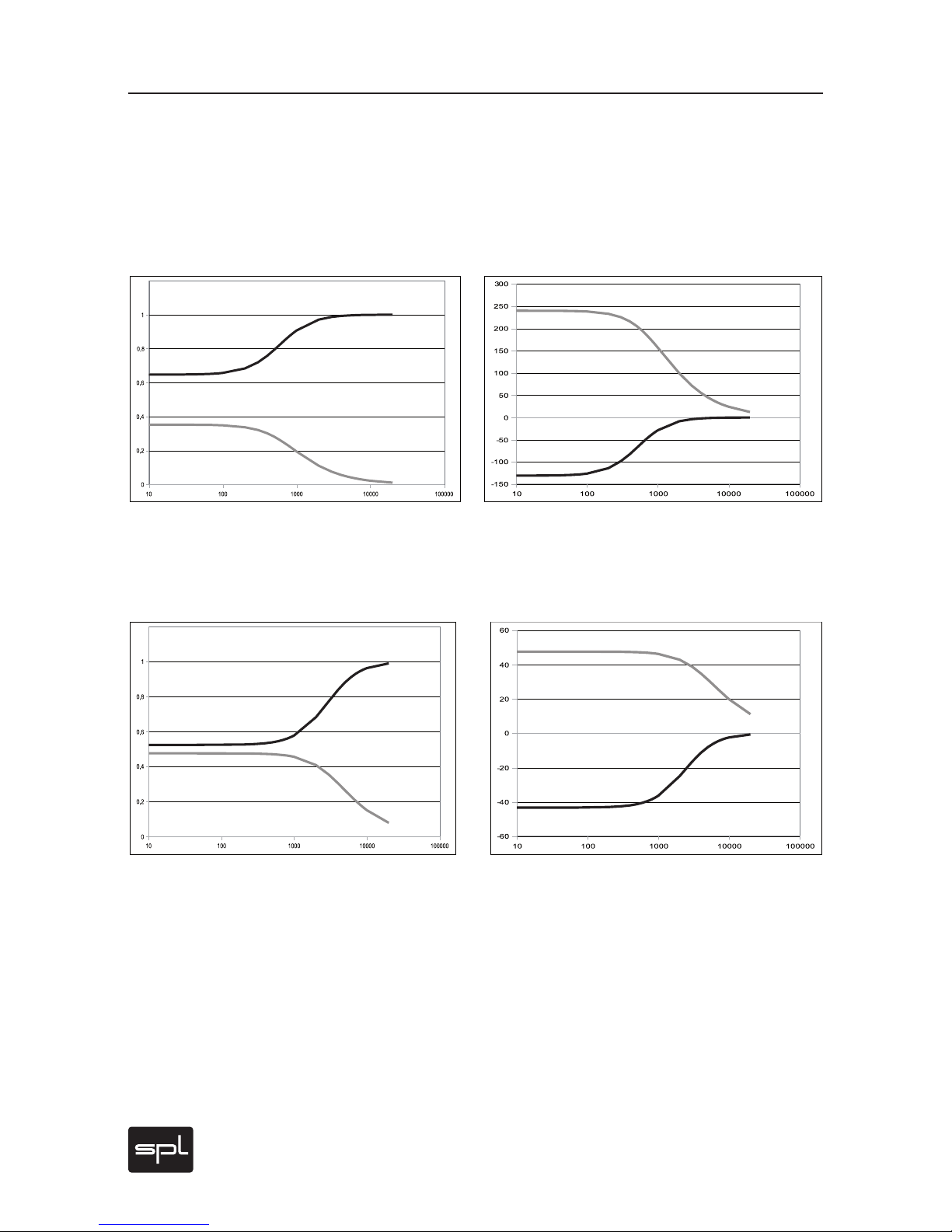
The following two diagrams show (on the left) the frequency response
of interaural level difference with respect to the interaural time difference (on the right) at maximum Crossfeed value and an Angle of 75
degrees.
The following two diagrams show, respectively (on the left), the frequency response of the interaural level difference and the interaural
time difference (on the right) at a maximum Crossfeed value and an
Angle of 15 degrees.
The black curves stand for the side of the direct sound wave front,
while the gray curves stand for the opposite side.
The larger the Angle value (and/or angle of an actual loudspeaker
placement), the greater the effect will be of shif ting the opposite side
toward more deeply lying frequencies, since with an increased spatial
arc around the head only lower frequencies will undergo proportionate
modification.
It should also become apparent that the Angle control is primarily depending on interaural time differences. Its influences on level differences are in contrast, comparatively slight.
Page 23
Phonitor 2
23
Control Elements
Crossfeed and Angle Parameters
The accentuated lines show at which Crossfeed values the Speaker Angle most
precisely matches the theoretically determined time difference values.
These, of course, are mainly a starting point to reproduce a real monitoring setup. Formulae for calculations from http://www.sengpielaudio.
com/LaufzeitdifferenzenBeimNatuerlichenHoeren.pdf
Angle
Switch
Crossfeed
Switch
Level
Difference
Time Diff.
(µs)
Speaker Angle
(Result)
Page 24
24
Phonitor 2
Control Elements
Source
The Phonitor 2 provides three different source connections. Use the
Source switch to select one. All three switches are named after the inputs on the rear. The RCA input is usually used to connect consumer
products. Do note, however, that the XLR inputs can also be used to
connect any unbalanced outputs. For more information on this topic,
please refer to page 16, „Connecting XLR to other socket formats.“
Output
This switch merges the output selection and mute options. You can
choose directly on the Phonitor 2 whether you want to listen to the output signal on your headphones or speakers. There is no need to unplug
the headphones when you listen through your speakers, nor to turn off
the power amp when you use headphones.
Cr/A, Off, All
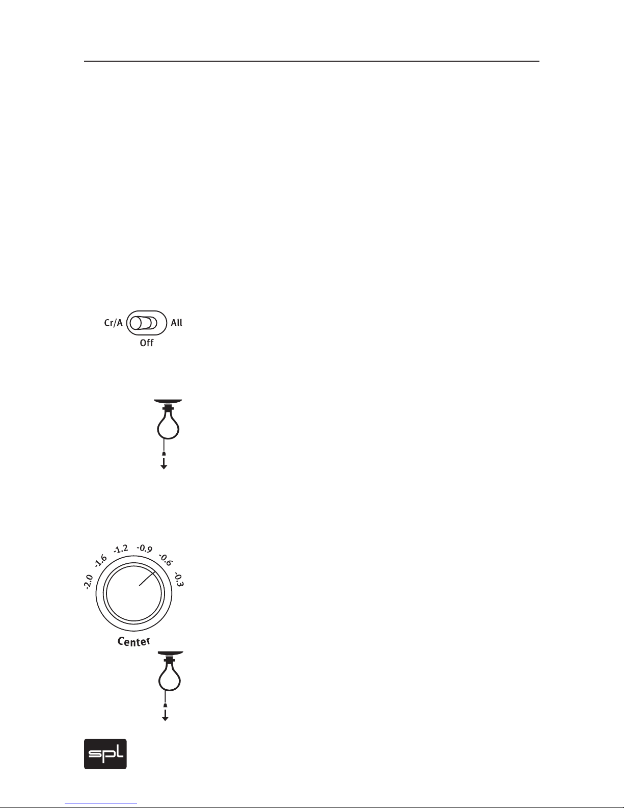
With Cr/A, Off, All you switch on or off Crossfeed and Angle functions
globally. “Cr/A“ switches Crossfeed and Angle in, “All“ activates
Crossfeed, Angle and Center, “Off” deactivates all three functions.
This provides for direct A/B comparisons. Your impression may at first
be that the results are not so spectacular as expected – until you consider that the Phonitor 2 is not an effects machine. Instead, reevaluate your aural impression by thinking about this: normal headphone
monitoring confronts you with a 180-degree sound stage – the “super
stereo width” has so little to do with loudspeaker playback. Now you
can gradually reduce this in 15 degree steps with the Angle switch.
Subsequently, using the Crossfeed function, you can simulate the
acoustic effect of room size and ambient characteristics on a given
listening device.
Center
With the Center control you may regulate the intensity of center signals
to compensate for the stereo signal processing with Crossfeed and
Angle. This Center signal is produced as a mono sum of the left and right
channels. Changes in these values are regulated through a finely graduated, six steps switch (0.3, 0.6, 0.9, 1.2, 1.6 and 2 dB).
In a normal headphone listening experience, the center signal is typically quieter than the stereo signals, which appear louder due to the
super stereo effect. If the sound stage width is narrowed through
changes in Crossfeed and Angle (so as to correspond to your actual
loudspeaker setup), the headphone center may likely sound too intense now. Lowering the center level will again return the center signal
to the correct volume in relation to the L/R stereo image. >
Page 25
Phonitor 2
25
If you are an audiophile listener you may find that you will not need
the Center function as you are mainly listening to finished recordings
that were mixed to sound well on loudspeakers. As a mix engineer you
will appreciate the center function as an essential tool for successful
mxing on headphones. The Center function helps to mix the phantom
center signals such as lead vocals, bass, kick and snare with the correct level to sound great on loudspeakers.
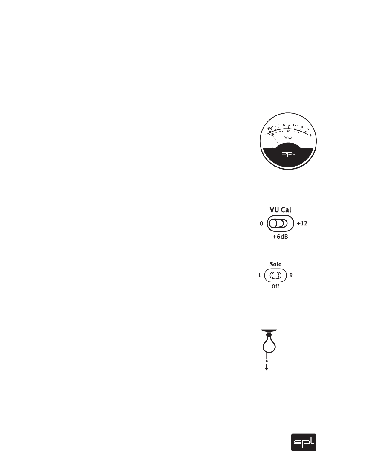
VU Meter
The VU meter displays the input level for each channel. Calibration is
set to +4dBU at 0 VU. The gauge indicates levels from -20 dB to +5 dB.
If necessary you can lower the sensitivity by 6 dB so that the gauge
goes up to +11 dB output level (see “VU Cal.“ below).
The VU meter is custom made to meet SPL specifications and assures
a balanced optical perception thanks to it’s optimized ballistics. The
integration time of the display complies with BBC requirements, rise
time up to 0 dB is approximately 300 ms.
VU Cal.
With this switch you can change the sensitivity of the VU display. If
you choose the +6 dB position, the range of the display is extended by
6 dB. With the +6 dB switch activated and the needle at 0 dB, a value of
+6 dB input level is displayed.
Solo
You can engage the Solo switch to monitor only the left or right channel of the stereo signal.
The Solo switch has three positions: L, R and OFF. The middle or OFF
position allows monitoring the stereo signal. Switch to L or R, and you
will hear only the lef t or right channels, respectively.
A selected solo channel defaults to retain in its respective left or right
position, and we call this function “Solo-in-Place”. However, should
you prefer to hear a chosen solo channel in both ears (“Solo-toCenter”), you can additionally activate the Mono switch. This Solo-toCenter variant also allows some interesting possibilities for comparison between two channels. You can, for instance, recognize immediately whether the sound of both channels contains comparably equal
highs and mids. Likewise you may ascertain quickly whether a signal
such as a voice, snare, kick or bass track (that you wished to locate in
the middle of the stereo field) has been placed properly – if not, this
setting will reveal different levels in the left and right channels.
Control Elements
Page 26
26
Phonitor 2
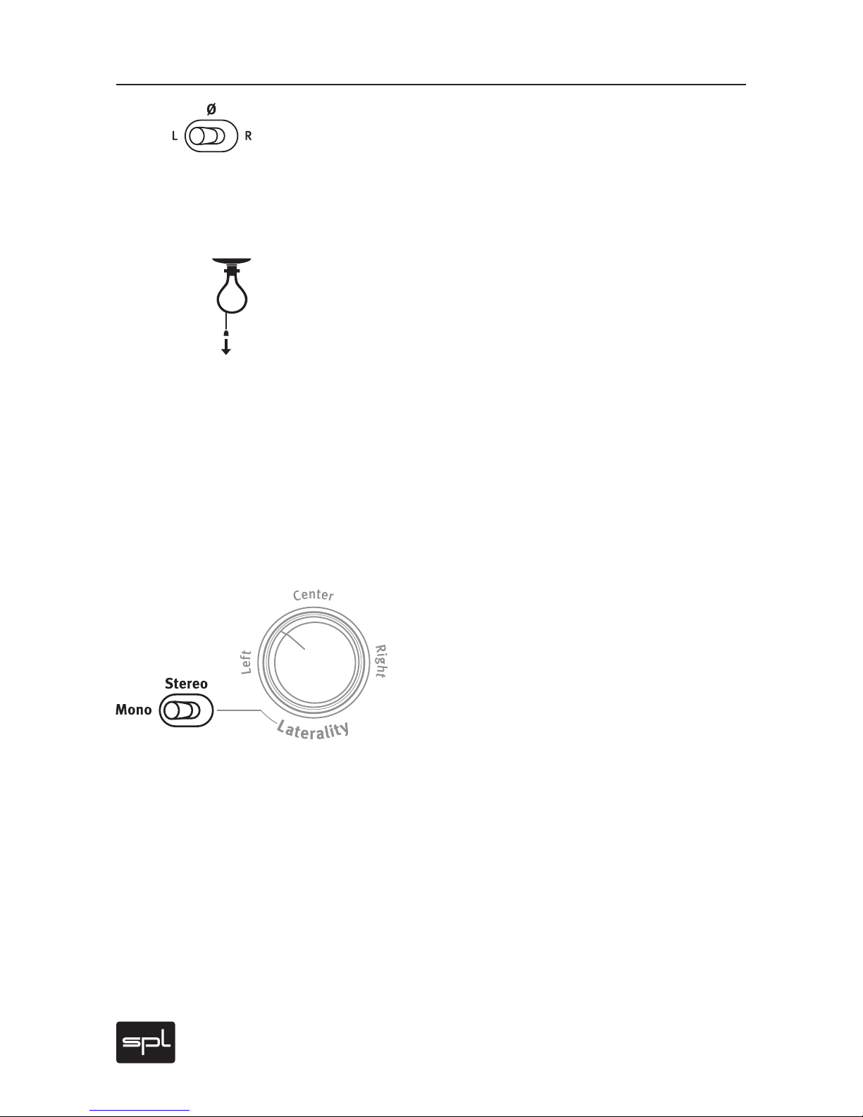
Phase ø
The phase reversal control is another important monitoring function. As with the solo function, you can choose between L, R and OFF.
Choose the middle position, OFF, to hear the stereo signal. Switching
to L reverses the left channel phase (thus inverts by 180°). The same
effect occurs in the right channel when switching to R.
With phase reversal and a simultaneous activation of the Mono
switch, you can generate the difference between both audio channels.
Depending on which channel’s phase reversion you have activated,
what remains will be the channel’s available stereo information. In this
differentiated signal you can, for instance, now judge whether signals
to be placed in the middle “sit” properly or not. If not, a remainder
of the center signal will not be cancelled out by the phase reversal –
something which should happen with a true mono signal. Before you
undertake this test, you should eliminate any stereo effects on the
channel you wish to test, as such reverb processing will tend to be retained and invalidate the results.
However, even more important for precision testing of the center signal can be to discern the intrusion of artifacts. For example through
this process you can easily detect distortion which may be introduced
digitally (via converters or internal DAW mixing).
Stereo and Mono
Usually this toggle switch is set to Stereo for regular
monitoring of stereo signals. The Mono switch creates a sum of the stereo channels.
If, per the above description, you employ this Mono
switch along with the Solo, the overall signal level
will be approximately 6 dB below a stereo signal and
mono-switch only. This is normal, since in Solo mode only a single
mono channel is active.
Aside from the above scenario, the Mono switch also offers important and useful functions in combination with Phase and Solo switches
in its ability to examine the mono compatibility of a mix. While such
compatibility tests are essentially the same as in earlier eras, they
nonetheless remain an important standard in radio mixing or vinyl
production.
Control Elements
Page 27
Phonitor 2
27
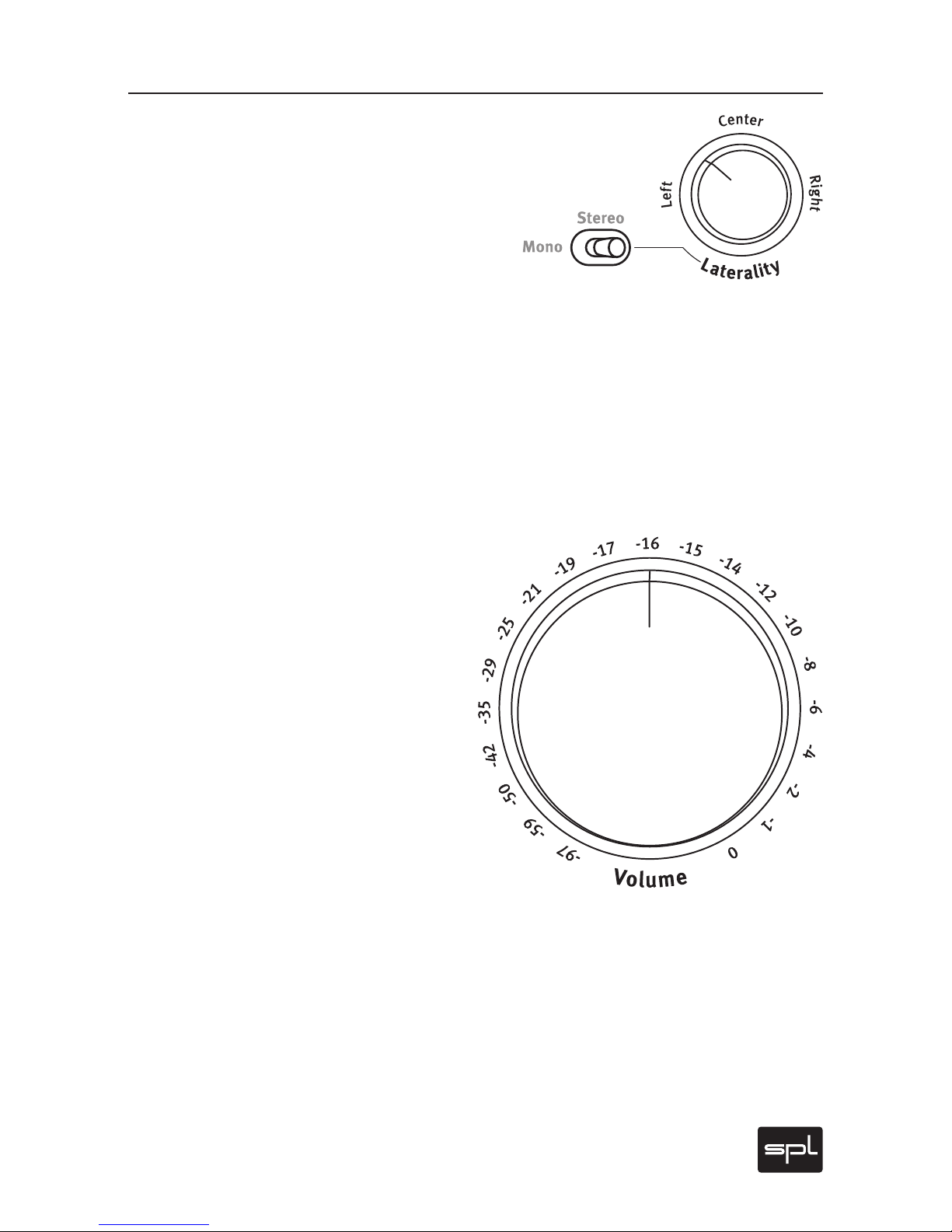
Laterality
In acoustics, laterality refers to the deviation of
sound perception to either of our ears. With the
Laterality control you can compensate perceived volume differences between channels that may be due
to hearing loss.
This control has a narrower range than conventional
balance controls. When it is turned fully left or right, the level of the
opposite channel is not reduced to zero. Its resolution is very high,
which means it can be finely adjusted. Further, Laterality works like
a scale with values ranging from +3dB to -3dB. This means that, when
hard left, the level of the right channel is reduced 3dB while that of the
left channel increases 3dB.
The maximum difference amounts to 6dB, which is more than enough
to compensate for significant differences: +6dB equates to doubling
the sound pressure level (to achieve a doubling of the perceived loudness, the overall level ought to increase 10dB).
Volume
The Volume level control allows you to decrease
the signal level from between 0 and -97 dB.
To this end we employ a high-grade ALPS RK27
motorized potentiometer. It distinguishes
itself through a high headroom, very low tolerance and excellent handling that on the one
hand offers sufficient resistance while, on the
other, avoids stickiness.
The Volume control is calibrated in a relative
dB scale that references the input level. The fully
clockwise position represents 0 dB, where the input
signal is led to the output with an unaltered level (unity
gain).
Control Elements
Page 28

28
Phonitor 2
Adjust Headphone Reproduction To Loudspeaker
Monitoring
The Phonitor 2 offers foremost a complete set of options required for
professional monitoring: Solo L/R, Phase Reverse L/R, Mono, Volume,
VU Metering.
In addition, new functions such as Crossfeed, Angle and Center Level
transform the Phonitor 2 from a traditional headphone amplifier into a
headphone monitoring amplifier, with which it is possible to achieve
reproduction equivalent to studio monitors, if essential factors of
music production are considered.
We recommend proceeding with the following five steps:
1. Initially choose your audio material from sources you know well,
and in a first production, that which is similar to what you wish to
mix. It is not sensible to listen to classic music while planning a
Phonitor 2 setup to mix a pop production. Classic music stereophony recording involves a much more restricted stereo width than pop
or rock music, where artificial “panorama stereophony“ often provides for a much broader imaging. Compare and match the volume
of speakers and headphones.
2. Note that you should be able to switch quickly and smoothly be-
tween speaker and headphones when making comparison tests. It
is also important that you can switch off the loudspeakers quickly
to avoid crosstalk into the headphone. The degree of loudspeaker
crosstalk into the headphones will of course depend on whether
you have open, half -open or closed headphones.
3. As starting points, first choose the following adjustments:
Crossfeed: 3, Angle: 30°, Center Level: -1,2dB.
4. Activate Crossfeed, Angle and Center. The audio channels will now
be mixed with time, level and frequency corrections calculated precisely to match what you hear when monitoring over loudspeakers.
You should now compare what you hear with headphones and loudspeakers. First, whether or not you have the correct width in your
stereo image. If this appears too narrow or too broad with the headphone, you have always two ways for further adjustments.
Increase Crossfeed. With this approach more of each channel
is mixed to the opposing side, but the Angle remains unaffected.
Technically speaking, this process changes the interaural level difference. However, the interaural time difference on the contrary
changes only minimally.
Operation
Page 29

Phonitor 2
29
Operation
Alternatively you can keep the Crossfeed adjustment identical
(thus keeping the interaural level difference), but for example increase the Speaker Angle. This way the interaural time difference
is increased, which in turn has the effect of a broader image. The
interaural level difference is only slightly altered. Do not be misled
by the scaled Speaker Angle degree numbers so that you think you
need to follow only those exact values given for your loudspeakers.
These values are to be considered as approximations for the determination of interaural time differences. In an individual installation,
a loudspeaker pair set up at a 30° angle may in fact be perfectly
represented with a 40° Speaker Angle switch adjustment at the
Phonitor 2.
If you are uncer tain about the angle your loudspeakers are set up,
you can calculate this as follows: You‘ll need a pocket calculator
with pi functions (in this case ‚arctan‘ = arc tangens) and a measuring tape. Measure the distance between both loudspeakers, that is,
between the cone midpoints, and divide the distance by 2. We call
this result A. Now measure the distance between the loudspeaker
centers and the location of your ears at the listening position. This
result we call B. The angle W, in which the loudspeakers are set up is
calculated according to the formula: W = arctan A:B.
5. After you have set up Crossfeed and Angle you can then determine
your Center Level setting. Although at normal hearing levels over
headphones the center signal generally seems too quiet, after
Crossfeed and Speaker Angle processing it then can seem too loud.
Therefore the center level can be lowered to avoid this effect.
After finishing these adjustment you should have achieved a
very good initial headphone equivalent of your loudspeaker
reproduction.
But as a final bit of advice we‘d like to emphasize that monitoring
over loudspeakers remains important. Every studio offers alternative monitoring with distinctive sounds (near field, mid field and
full range). Experienced engineers hear a mix on the portable radios and through car and home stereos. And everywhere a mix will
sound different – just as it will over headphones. But for mixing, the
Phonitor 2 gives results with headphones that are as close to (near
field) monitoring as possible.
Page 30

30
Phonitor 2
Specications
Inputs
XLR connectors, electronically balanced
Impedance: bal. ca. 20 kohms, unbal. ca. 10 kohms
Max. Input Level: +32,5 dBu
Outputs
Monitor/Line Outputs: XLR connectors, electronically balanced
Frequency Range: 4 Hz to 480 kHz ( -3 dB)
CMR: -82 dBu
At 1 kHz, 0dBu input level and unity gain
Crosstalk at 1 kHz: -106 dB
THD&N at 1 kHz: 0,00085 %
At 0dBu input level and unity gain, 1 kHz, 100 kohms load
Noise: Unweighted -101,87 dB
A-weighted - 104,76 dB
CCIR: -96,1 dB
Dynamic Range: 134,37 dB
Headphone Output
6,3-mm TRS connector
Pin wiring: Tip = Lef t, Ring = Right, Sleeve = GND
Impedance: 0,18 ohms
Attenuation Factor: 180 @ 40 ohms
Frequency Range: ‹10 Hz to ›480 kHz ( -3 dB)
CMR: -82 dBu
At 1 kHz, 0dBu input level and unity gain
Crosstalk at 1 kHz: -106 dB
THD&N at 1 kHz: 0,00091 %
At 0dBu input level and unity gain, 1 kHz, 100 kohms load
Noise: Unweighted -101,12 dBu
A-weighted - 103,98 dBu
CCIR -95,02 dBu
Dynamic Range: 133,62 dB
Power Amplier
Max. Output Power:
2x 1 W (+30 dBu) at 1 kHz and 600 ohms connected impedance
2x 2 W (+30 dBu) at 1 kHz and 300 ohms connected impedance
2x 3,7 W (+30 dBu) at 1 kHz and 120 ohms connected impedance
Power Supply
Voltages: 230 V AC, 50 Hz / 120 V AC, 60 Hz
Power Consumption: max 23,7 VA
Fuses: 100-120 V AC: T 1 A/200-240 V AC: T 500 mA
Measurement & Weight
Height x Width x Depth (mm):
99 x 277 x 305
Weight: 4,3 kg
0 dBu = 0,775 V. Specications subject to change without notice.
Page 31
Phonitor 2
31
Measurements
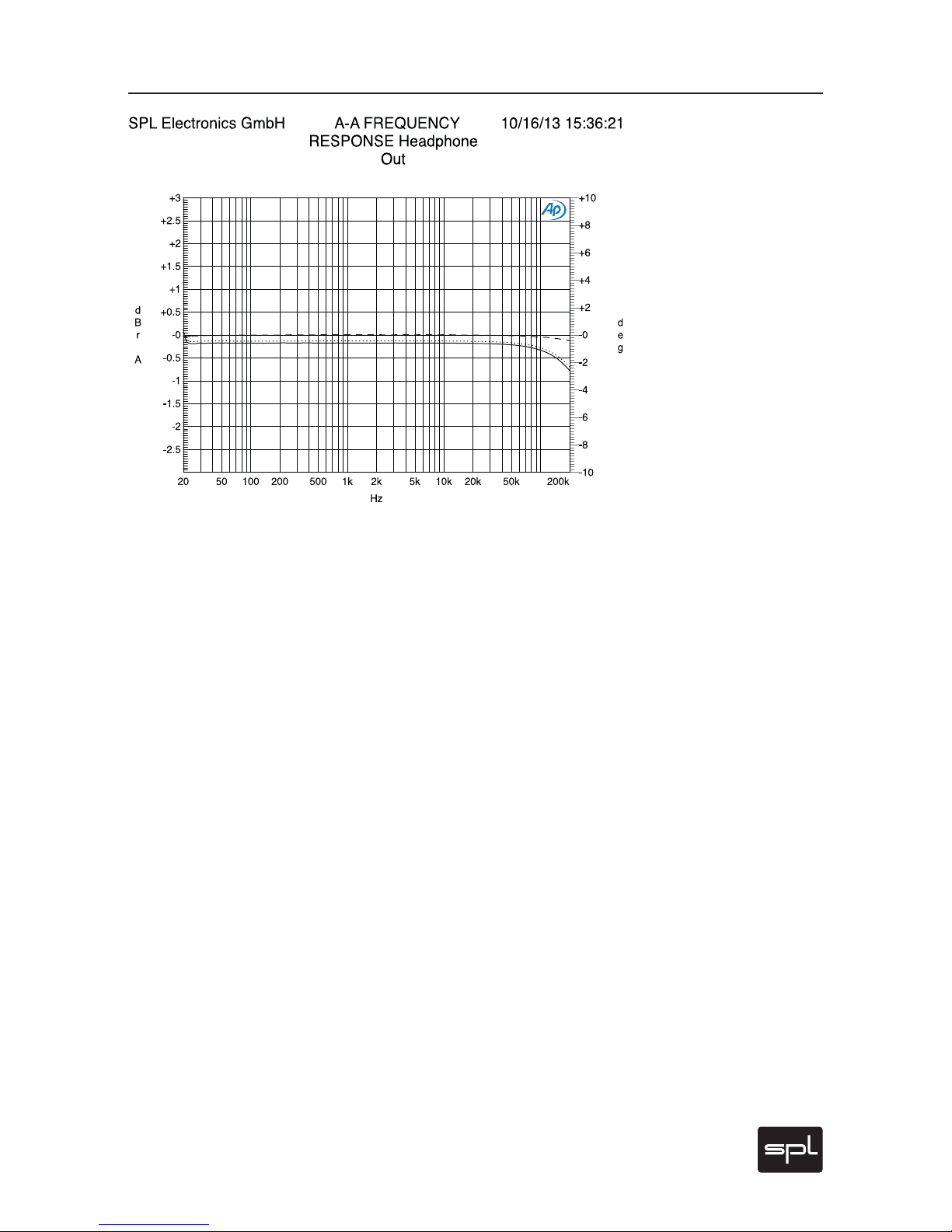
Frequency Response Input/Headphone Output,
Left and Right Channel Measuring output
and input 600 ohms, Volume control Phonitor 2 0 dB:
‹10 Hz to ›200 kHz (-0.2dB; ‹10 Hz to ›480 kHz @-3dB).
The large frequency response range excludes that the frequency spectrum is limited at any point. Formants and octaves of an instrument’s
sounds cannot be narrowed.
Phase Response Input vs. Output, Left and Right Channel
Measuring output and input 600 ohms, Volume control Phonitor 2 0dB.
This measurement shows the minimum deviation of phase in the
upper frequency range. Phase response describes the time difference
between input and output signal – the less, the better. The extremely
tight phase response up to 50 kHz excludes any audible effects.
Page 32
32
Phonitor 2
Measurements
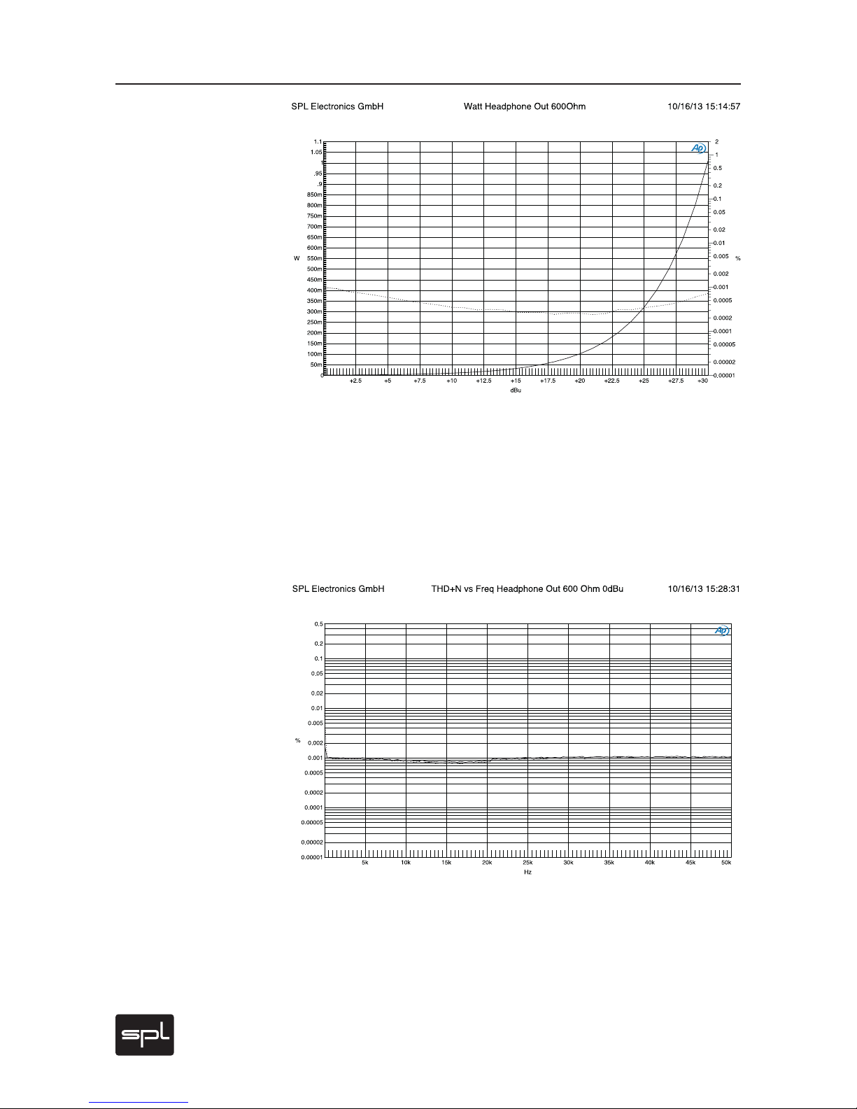
THD vs. Frequency
Measuring output and input 600 ohms, Volume control at 0 dB. THD vs.
frequency range from 10 to 20 kHz at 0 dB over both channels. Values
are extremely low below 0.001% throughout the whole range; even in
long sessions this ensures listening without ear fatigue.
THD vs. Output Level (W)
Measuring output and input 600 ohms, Volume control at 0 dB. This
measurement represents an analysis of THD values over the complete
output level range. High THD values can be perceived as rough sounds
and overemphasized highs. In usual operating ranges around 0 dBu,
the Phonitor‘s THD values are extremely low. Volumes that would result from 10 dBu are already far above healthy levels.
Page 33
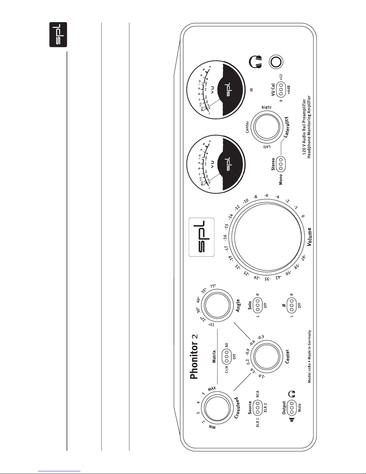
Copy Master: Recall Sheet
Studio/Listening Room
Date
Headphones
Speakers
Page 34

Model 1280
Manual Phonitor 2
 Loading...