

Page 1
SPL Analog Code ® Plug-in
Manual
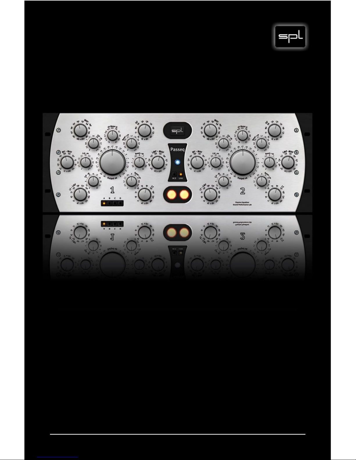
Passeq
Dual-Channel Three-Band EQ
Page 2

2
Passeq Analog Code® Plug-in
Manual
Content
Passeq Analog Code® Plug-in, Model Number 1040
Manual Version 2.0 – 12 /2 0 11
This user‘s guide contains a description of the product. It in no way
represents a guarantee of particular characteristics or results of
use. The information in this document has been carefully compiled
and verified and, unless otherwise stated or agreed upon, correctly
describes the product at the time of packaging with this document.
Sound Performance Lab (SPL) continuously strives to improve its
products and reserves the right to modify the product described in
this manual at any time without prior notice. This document is the
property of SPL and may not be copied or reproduced in any way, in
part or fully, without authorization by SPL electronics GmbH.
SPL electronics GmbH
Sohlweg 80, 41372 Niederkruechten, Germany
Phone: +49 (0)2163 983 40, Fax: +49 (0)2163 983 420
E-Mail: info@spl.info, Website: spl.info
© 2011 SPL electronics GmbH. All rights reserved.
The SPL logo, Analog
Code
®
, Vitalizer® and Atmos® are trademarks of SPL electronics GmbH.
All other
logos and bra n d names ar e registere d trade m ark s of their resp e cti ve own e rs .
Installation 4
Plugin Alliance Activation 4
System Requirements and Compatibility 4
MAC and Windows Installation 4
Introduction 5
Glossary, SPL Analog Code Plug-ins 5
The most powerful passive EQ system ever made, The Passeq
Analog Code® Plug-in, Special Features 6
Page 3
3
Passeq Analog Code® Plug-in
Content
Operation 7
Mouse wheel control for all rotary knobs, Keyboard Shortcuts,
Mono, stereo or multi-channel operation 7
Layout of Operational Elements 8
Allocation of Frequencies 9
Control Elements 10
LF-LMF Cut and LF Boost 10
MF-MHF Cut and LMF-MHF Boost 11
MHF-HF Cut and HF Boost, HF Boost Q with Proportional Q 12
MHF-HF Cut 13
Output Control, Settings, Channel Switch 14
M/S and Link, M/S, Link 15
Using Equalizers 16
Basic Approach, EQ Yin & Yang 16
First control levels, then apply EQ 17
First cut, then boost; Reducing bleed outside an instrument‘s
range, Reducing bleed within an instrument‘s range, Boosting harmonic frequency levels 18
Boosting fundamental levels, Cutting fundamental levels,
Emphasis of an instrument‘s main frequencies 19
In the mix—or not?, Splitting frequency bands 20
Complementary filtering 21
Processing Examples 22
Classical instruments and their frequencies 23
The Basics of Frequency Filtering 24
Frequency and Energy, Tone and Sound 24
Sound Correction and Sound Design 25
Frequency Filters, Filter Types 26
Shelf Filters, Peak Filters, Bandwidth 27
M/S Basics 28
M/S Stereophony 28
Page 4

4
Passeq Analog Code® Plug-in
Plugin Alliance Activation
Your Analog Code plug-in must be activated in your Plugin Alliance
account. You can set it up and log into your account anytime at
http://www.plugin-alliance.com
For details about the activation process, read the Plugin Alliance
Activation Manual. The PDF file is stored in the same folder of your
computer like this product manual file.
Alternatively, the following web page provides the same information: http://www.plugin-alliance.com/activation
System Requirements and Compatibility
For details about system requirements and supported platforms
or formats visit http://www.plugin-alliance.com/compatibility
MAC and Windows Installation
1. Check for the latest plug-in software version before installation:
http://software.spl.info/download
2. Execute the installer file and follow the instructions.
Installation
Page 5

Passeq Analog Code® Plug-in
5
Introduction
Glossary
Host Program: program on which the plug-in is running (Pro
Tools, Cubase, Logic, etc.).
M/S: Mid/Side encoded signal information as an
alternative to standard left/right (L/R) encoded
stereo signals. For more background information
on the M/S technique read page 28 and 29.
SPL Analog Code® Plug-ins
While SPL hardware products have been fascinating audio professionals from home studio owners to mastering engineers in
the world’s most renowned facilities for years, the need for this
technology in the form of plug-ins has also been an ever-growing
demand. With the Analog Code® plug-ins we have finally accomplished our much desired goal: to transfer to the digital domain the
high quality we have striven to achieve with our analog processors
throughout several decades.
The first time we ever heard a software that fulfilled our expectations, one of our hardware developers said to the programmers:
“you have cracked the Analog Code” — thus was coined the name
of our digital products.
Page 6

6
Passeq Analog Code® Plug-in
The most powerful passive EQ system ever
The original Passeq hardware is the first passive EQ which provides three separate frequency ranges for both boost and cut
stages. One famous, if not the most famous, passive design was
the Pulteq EQ from the decades of the 1950’s and 60’s. This EQ
sported two frequency bands (low and high frequencies, or LF and
HF), and had only a few switchable frequencies to offer. In contrast, the Passeq has 12 switchable frequencies per band, totaling
36 boost and 36 cut frequencies. Boost and cut frequencies are
NOT identical, thus the resultant 72 frequencies per channel offer
an enormous choice for the most elaborate EQ curves.
The Passeq offers for the first time passive filter control possibilities extending throughout the relevant audio frequency range—
and that with an unheard of abundance of filter choices.
The Passeq Analog Code® Plug-in
The fantastic qualities of SPL’s Analog Code programming faithfully
reproduce the unique sound quality of the original hardware. All
the complex interactions between each single filter are reproduced
in every detail. One of the peculiarities of passive filter designs is
that they can be seen as one big filter — the signal always runs
through the whole network. Whenever the settings change, a flow
of interactions takes place between the filters, providing the characteristic and unique sound of these EQs — something that will
never happen with active EQ designs.
Special Features
Two Graphical User Interfaces (GUI): The plug-in list of your host
program will show two entries after installation: “Passeq” and
“Passeq Single.” Aside from the standard dual-channel GUI, the
single GUI represents a space saving alternative showing one
Passeq channel. Nevertheless, the single version can be applied
to a stereo track — you simply control both channels simultaneously with one knob. >
Introduction
Page 7

Passeq Analog Code® Plug-in
7
Basics
Introduction
Operation
M/S Mode: as an alternative to L/R processing you can also switch
to M/S mode for processing the mid and side information of a
stereo panorama. Read more on page 15 (“M/S”) and 28 ff (“M/S
Basics”).
Mouse wheel control for all rotary knobs
All SPL Analog Code plug-ins support mouse wheel control for
rotary controls and faders. Place the mouse cursor over a rotary
control and move the scroll wheel of your mouse to adjust the setting. Hold the CTRL (Windows) or COMMAND (Apple) key while
moving the scroll wheel to make fine adjustments; the resolution
of the mouse wheel is increased, making fine-tuning easier.
Keyboard Shortcuts
All SPL Analog Code plug-ins support format and OS specific functions for value reset, fine adjustment and mouse control. For more
detailed information please refer to the host program’s documentation.
Mono, stereo or multi-channel operation
The Passeq plug-in can be used either for mono or stereo operation. You can also use the Passeq as a „Multi-Mono“ or multi-channel plug-in, as long as your host program supports this function.
Page 8

8
Passeq Analog Code® Plug-in
Overview
Operation
Layout of Operational Elements
Initially one might be struck by the circular arrangement of the
Passeq’s control elements. As unusual as this first appears, the
more understandable and clearer this layout becomes when one
looks closer.
Along with the fact that we simply like this design from an aesthetical view, this layout makes even more sense with respect to the
idea of the passive EQ concept itself: In a passive design, filters for
boosting and cutting a frequency range are physically separated
from each other. Reflecting this fact, the elements left of the central output control perform level cuts, while controls to the right of
this central regulator serve as signal boost controls. Cut and boost
switches are positioned next to the appropriate frequency band
selector and frequency bands are arranged from low to high from
the standpoint of both physical and frequency range layout—all
in all a clear overall functional picture though without much in the
way of boring routine.
Passeq Single – the space-saving single channel GUI
Page 9

Passeq Analog Code® Plug-in
9
Overview
Operation
Allocation of Frequencies
One of the greatest Passeq design challenges was in determining the choice of frequencies, which in contrast to parametric EQ
designs, are fixed or nonadjustable. One could accept standardized values from such as the so-called ISO frequencies, but such
measurements stem too much either from conventional measurement standards or those from room corrections rather than choices
of what may be musically more sensible. In assigning the Passeq‘s
frequencies it was inevitable that we would rely on the nearly 30
years of experience of SPL’s chief developer, audio engineer and
musician, Wolfgang Neumann.
To enhance further our achieving this musical objective many audio
experts and musicians were consulted regarding their favored frequencies. Among the many, David Reitzas, Michael Wagener, Bob
Ludwig, Ronald Prent and Peter Schmidt offered valuable advice.
From this point of departure we managed to determine that there
is definite agreement among professionals about their preferred
musical frequencies, and these differ clearly from the standard ISO
choices.
The results also showed that the closely meshed boost and cut frequencies are important and sensible. Through them one can on the
one hand focus more precisely on a certain frequency, and on the
other, offer the option of influencing the Q factor (which is typically
rather small in passive designs) by creating so-called S curves. An
Example: Assume you wish to boost in the mids around 320 Hz, an
instrument or voice level while at the same time avoiding a boost
to the frequency range below it due to the small Q factor (high
bandwidth) of the filter, and perhaps even lower it. In this case,
let’s say you choose the LMF-MHF boost band and increase the
chosen (320 Hz) frequency range by about 3 dB. At the same time,
you chose a 4 dB reduction in the LF-LMF cut band. The close proximity of the chosen frequencies allows you achieve an increase in
the slope between the two. This is “S slope EQ-ing” at its best, and
in this discipline, the Passeq is a world champion in both options
and results.
Page 10

10
Passeq Analog Code® Plug-in
Low Frequency Bands
LF-LMF Cut and LF Boost
The low cut frequency range extends from 30 Hz to 1.9 kHz
and will be ref erred to in this text as LF-LMF (Low to LowMid frequencies ). In con trast, the low boost (LF Boost)
band en com passes a range of 10 Hz to 550 Hz. The maximum available in crease in this LF boost band is (+)17 dB,
while the maximum reduc tion of the LF-LMF cut band is
(- )22 d B.
Optically these filter bands may be represented as having
a shelving characteristic with an 6 dB slope. Passive filters do not allow for direct alteration of the slope gradient because this quality is pre-determined by component
selection and not, as with active filters, by a variable value.
The lowest frequencies begin here with 10 Hz, then follow
with 15, 18, 26, 40 Hz, and so on. At this point one might think
that such a lavish set of frequency choice in this range might be
a bit overdone, as there is acoustically a rather limited amount of
audio material of any real significance below 26 Hz. However, these
choices are anything but arbitrary. These frequencies represent
a consistent -3 dB point of a sloping down response curve. That
is, the gentle 6 dB slope also allows frequencies above 10 Hz to
be processed. For the hardware original, special condenser/coil/
resistor filter networks have been designed for each frequency
range. The choice of one or the other inductances produces differences in sonic coloration even when limited differences between
frequencies such as 10 Hz or 15 Hz play a subordinate role. Along
with this differing phase relationships may come into play and
affect tonal color. Because modern productions often demand a
definite number of choices in an engineer’s options for achieving
an optimal result in bass emphasis, the Passeq has been designed
with a very complete set of low frequency options to insure realizing these goals.
Control Elements
Page 11

Passeq Analog Code® Plug-in
11
MF-MHF Cut and LMF-MHF Boost
The midrange bands elevate the Passeq to a complete combination of filter options that classic passive
designs do not offer. Both midrange bands exhibit
peak filter characteristics, that is, when viewed from
the boost band, the frequency curve appears as bellshaped slopes above and below the chosen frequency
range. The slope or Q-value is, again, not variable, but
attuned through the choice and configuration of the
passive filter‘s components for a maximum in musical efficiency, relying in the Passeq on its developer,
Wolfgang Neumann‘s years of musical experience. The middle
bands‘ peak structure is chosen for a clean separation of LF and HF
bands. Were the choice here to be for a shelving filter design, too
many neighboring frequencies would be processed, with resulting
undesirable influences extending into LF and HF bands. Along with
this is the simple fact that a midrange peak filter characteristic is
accompanied by a more easily focused center point processing of
critical voice and instrument fundamental frequencies.
The MF-MHF cut band overlaps the LF-LMF cut band by approximately an octave, with its lowest frequency extending from 1 kHz.
The LF boost and LMF-MHF boost bands are set up in a similar
fashion, with the lowest LMF-MHF boost band frequency set at
220 Hz and thereby 1-1/2 octaves under the highest LF boost band
frequency. The maximum values of the MF-MHF cut and LMF-MHF
boost band extend from -11.5 dB to +10 dB.
The overlapping band characteristics give a good idea of the available degree of precision in frequency adjustment: For example,
one can boost in the LMF-MHF boost band at 220 Hz while in the
LF boost band, 240 Hz can be followed by 320 Hz in the LMF-MHF
boost band: The next step could be at 380 Hz in the LF boost band,
followed by 460 Hz in the LMF-MHF boost band and 550 Hz in the
LF boost band ...
Mid Bands
Control Elements
Page 12

12
Passeq Analog Code® Plug-in
High Bands, Setting HF Boost
Control Elements
MHF-HF Cut and HF Boost
Passeq’s high frequency bands have a different layout for
the cut and boost ranges: The MHF-HF cut band exhibits
a (wide-band) shelving characteristic, while the HF boost
band exhibits a variable Q, peak filter characteristic.
As seen above, one can also note and intensification in
choice of frequencies in the high range. Here the same
reasons apply as in prior cases: The individually designed
and constructed coil-condenser-resistor configurations
of the hardware original result in slightly differing sonic
characteristics. Thus beginning at 10 kHz there are seven
additional switchable frequencies. The available vari-
able Q (ranging from Q=0.1 to Q=1.0) allows the engineer
access to an enormously flexible range in high frequency boost
options.
HF Boost Q with Proportional Q
With the proportional or variable Q principle, boost control settings would apply only if the HF boost Q were to be set at Q=1.0
(control set fully clockwise). Were the value to be reduced (thus
increasing the bandwidth), the boost would also be reduced. This
can lead to a situation wherein, for example, a HF boost Q setting
of 0.1 and a boost of 3 dB would result in effectively no audible
boost in the chosen frequency—at this value the Q value resides
at about 0.3 dB. With this Q value, don’t hesitate to turn up the
HF band boost control to its full 12.5 dB setting—this results in an
actual overall increase of around 3.5 dB. Narrower Q settings, for
example, to 0.6, result in further level boosts again. >
Page 13

Passeq Analog Code® Plug-in
13
Setting HF Boost, MHF-HF-Cut
Control Elements
The advantage of proportional Q as compared to constant Q
designs rests with the musically superior way it functions. The
wave energy which resides below the bell curve remains essentially the same and in the process, retains the balance of high
frequencies in relation to the entire frequency spectrum as one
experiments with varying Q values. While it is true that one must
think independently of the scaled HF boost dB values in such cases
(because these only apply to a value of 1), the result is a simpler,
more musically sensible and worthwhile way to work that does not
require continual additional corrections.
MHF-HF Cut
The MHF-HF cut band is similar to a shelving filter that
can reduce higher frequencies in a wide bandwidth. It is
appropriately wide, beginning with 580 Hz and extending
to 19.5 kHz, a range of over 5 octaves and overlapping the
lowest, LF-LMF cut band by just about two octaves. With
it one can lower a very wide bandwidth and with the peak
mid range filters further reduce—or raise—specific ranges. The
process can result in the creation of very interesting curves. Here
the maximum cut is -14.5 dB, while the maximum boost reaches
+12.5 dB.
The Passeq is not limited to any one particular kind of application,
and, for example, is also especially well suited to processing individual instruments in recording sessions. In such cases the wide
downward reaching MHF-HF cut band may be play an exceptional
role. Individual instruments can easily be cut upwards, either
to give them a more compact sound or when higher frequencies
might be supplied from different microphone—or because the mix
simply suggests it.
Page 14

14
Passeq Analog Code® Plug-in
Output Level, Settings
Control Elements
Output Control
The Output control serves as output level regulator. If
the output level increases due to frequency boosting, it can always be reduced again to match the input
level. When you start using the plug-in, the control
is set fully clockwise, i.e. at 0 dB. From there you can
reduce the level to a maximum of -66 dB. The scale
star ts with a very fine resolution to allow for smooth adjust-
ments, especially in the first half of the control range.
Settings
The four SETTINGS buttons allow you to save all your settings with a simple mouse click. As soon as you click on another
SETTINGS button, the current settings are saved under the previously active preset. For example: In the image shown here, all
parameters would be saved under preset “A” if you were to click
on another button.
Any previously saved preset can be recalled with a simple mouse
click on the corresponding but ton; you can then use or edit the settings. If the host program allows it, the presets can also be automated so you can use different settings at different points. As long
as you work in a specific session of the host program and the plugin is installed, the settings are saved and can be recalled afterwards. When opened, the plug-in loads the active preset settings
instead of the default settings. If you remove the plug-in from the
host program all presets are lost. To erase all presets at once you
can remove the plug-in from the host program and then reinstall it.
Channel Switch
Two illuminated switches in the center of the standard GUI
front activate or bypass processing for the left or right chan-
nel. On the Passeq Single GUI, the right switch is always
grayed out; the left one always activates or deactivates the Passeq
Single, regardless of whether processing is mono or stereo.
Page 15

Passeq Analog Code® Plug-in
15
M/S and Link
The M/S and LINK switches are only available in the standard
GUI, because separate operation of each channel is required
to use them. IMPORTANT: Usually, the LINK switch should be deactivated when you activate M/S — otherwise the settings for the
mid signal are applied to the side signal as well.
M/S
As an alternative to L/R encoded stereo signals, there is one technique that is particularly useful for signal processing during production: M/S. “M” stands for Middle (or Mid) and “S” for Side,
which means that signals are separated from the middle to the
sides, instead of from left to right.
The M/S switch activates an M/S encoding of the L/R signals. Now
you can process the mid information with the left channel and the
side information with the right channel. M/S encoding is only used
for processing; decoding into L/R format is done before the signal
is output. Note that both encoding and decoding is lossless.
The use of a mid (M) and a side (S) signal instead of the usual L/R
signal results in a much wiser musical processing. High-energy
Mid signals (vocals, snare, bass guitars, etc.) can be easily separated from Side signals (guitars, keyboards, cymbals, etc.). When
processing sum signals, M/S encoding is often the best option to
be able to target single elements within a mix. Also refer to “M/S
Basics“ on page 28 ff.
Link
The LINK switch couples both channels. This ensures the same
settings for the two channels, and it takes half the effort to set
them up.
The left channel always controls the right channel. If you activate
the LINK mode, the current settings on the right channel are not
overwritten, even if they are different. Settings are only transferred once LINK mode has been activated.
M/S, Link, Channel Switch
Control Elements
Page 16

16
Passeq Analog Code® Plug-in
In the arenas of recording and mixing one can generally distinguish
between two main goals in applying EQ: The first is sound correction, or sound design through processing of individual channels
while the second may be improving their separation or presence
in the mix. In the overall recording process there may be deficiencies due to technical problems, for example, noise or bleeding
of neighboring instrument sounds that detract from the natural
quality of the desired instrument. Through frequency response
characteristics of a microphone or phase shifts due to reflections,
energy at certain frequencies can be reduced or get lost, denigrating the original sound quality of an instrument. EQ is probably the
most important tool to combat these problem areas. Moreover, an
instrument‘s sound can also be accentuated or emphasized—to
the point that this becomes in its own right a creative sonic activity
with a production made only possible by the employment of EQs
and their special characteristics.
Basic Approach
While we would never assume that in creative and artistic work
there should be absolute rules, and this also applies to work with
EQ: There is no such thing as “The Voice” or “The Kick Drum” or
“The Piano”. The following is thus offered strictly as a basic orientation or starting point for such work, and should not be misconstrued as dogma or any other kind of absolute. Nonetheless,
in order to achieve sometimes hard-to-define goals when applying
EQ, it really is important to be aware of and be able to use a few
accepted basic musical and technical guidelines.
EQ Yin & Yang
This section on “EQ Yin & Yang” reproduces thoughts and verbalizations by Bob Katz, whose superb Focal Press book based on a
series of lectures entitled, “Mastering audio, the art and the science”, we highly recommend. >
Using Equalizers
Page 17

Passeq Analog Code® Plug-in
17
In Chinese philosophy, Yin and Yang describe unconditionally bound
opposites within some kind of unity, which in turn, both complement and conflict with one other. This idea also provides an insightful analogy to the understanding of the connection between music,
harmony, fundamentals and harmonics. This mutual bond and interaction between such opposites creates inevitable and mutual reactions and repercussions in the other whenever something occurs to
one. Here are a few examples:
• A reduction in the lower middle range around 250 Hz can have
a similar effect as an increase in the presence region of 5 kHz.
• Added energy in the very high region (15-20 kHz) can create the
impression of having made the bass and lower mids thinner.
• Adding warmth to a voice will reduce its mix presence.
• Working with EQ and this Yin and Yang principle means ideally to consider always such implied repercussions of work
in one frequency—for example, that in working to enhance
warmth, that one might want to avoid losing presence.
• Harshness in the upper middle to lower high range can be
countered with more than one approach: A harsh trumpet section may be improved through a reduction around
6-8 kHz, or with an increase at around 250 Hz. Both of these
measures result in a warmer sound, but the decision of which
to use should depend on which of the two also works best in
the entire mix.
• Moreover, one should never forget how easy it is, while working intensely with isolated elements of a mix, to fall into the
trap of forgetting how such elements can influence, for better
or worse, the rest of the mix.
First control levels, then apply EQ
Badly adjusted levels often induce us to misuse EQ in misguided
efforts to correct them. As soon as one has the feeling that he or
she needs more that 6 dB in EQ (boost), one should investigate
thoroughly whether or not initial levels have been set properly.
Using Equalizers
Page 18

18
Passeq Analog Code® Plug-in
Using Equalizers
First cut, then boost
“The ear” is more used to energy reductions in a frequency
range, thus boosts attract more attention. That is, a 6 dB boost
is perceived to be similar in amount to a 9 dB cut. Therefore when
wishing to emphasize one frequency, it is typically better first to
consider a reduction in others. The result will bring more transparency and clarity as well as reduce possible unwanted coloration
of the signal.
Reducing bleed from other instruments or
noise outside an instrument‘s range
Wide band filters setups should be chosen with threshold frequencies in ranges from one-to-two octaves above or below the
highest or deepest instrument‘s frequency. Example: To eliminate
cymbal bleeding in a kick drum recording, one should try a setting
from about 10 kHz with a 10-15 dB cut.
Reducing bleed within an instrument‘s range
The main frequencies of the bleeding instrument should be
reduced as far as possible while avoiding to alter the natural
sound of the main instrument in an unnatural way.
Boosting harmonic frequency levels
Harmonic enhancement is one of the foremost techniques for
increasing the clarity and definition of an instrument. An overview
for three typical instruments:
Bass – 400 Hz: Bass lines will be accented
Bass – 1500 Hz: More clarity and attack sounds
Guitar – 3 kHz: Clearer attacks
Guitar – 5 kHz: Brighter, more brilliance
Vocals – 5 kHz: More presence
Vocals – 10 kHz: Brighten up
Note that each instrument will have at least two frequencies where
EQ can achieve a greater clarity or brilliance.
Page 19

Passeq Analog Code® Plug-in
19
Using Equalizers
Boosting fundamental levels
Inexperienced audio engineers will often first try to make corrections by boosting fundamentals, something which in fact should
be the last thing one considers. Boosting fundamentals typically
lowers clarity and produces a muddy sound. If two instruments are
playing the same part and thereby produce the same fundamental,
raising these levels will lead to a decrease in the sonic difference
between them, (i.e., will make the two instruments sound more
alike and lower their intelligibility in the mix). This is also true
when two instruments play similar parts in the same key.
Exception: When an instrument sounds thin or small, boosting
the fundamental can help. Or perhaps a microphone was poorly
placed or the harmonics had been raised excessively through EQ.
Finally, increasing fundamental levels can also play a constructive
role when instruments play alone or as soloists with others in the
background.
Cutting fundamental levels
Cutting fundamental frequencies provides for a perceived increase
in harmonics and is therefore an effective alternative to boosting
harmonic levels. This is a common practice in Rock/Pop productions that can be effective in all musical recording genre. Three
examples:
Bass, Reduction at 40 Hz: limits boominess, increases presence.
Guitar, Reduction at 100 Hz: limits boominess, increases clarity.
Voice, Reduction at 200 Hz: limits muddiness.
Emphasis of an instrument‘s main frequencies
For this purpose a bandwidth of 1 and 1/3 octaves is generally a
very good starting point—in other words, this range best encompasses that of most instruments‘ frequency spectrum. This can
be somewhat narrower with percussion instruments, while it is
recommendable to consider a wider bandwidth for melody instruments such as voice or bowed strings. The boost value should
remain between 3 and 6 dB.
Page 20

20
Passeq Analog Code® Plug-in
Using Equalizers
In the mix—or not?
The more an instrument is placed “outside” a mix (resp. above or
in front of a mix), the more natural its sound should remain. When
already embedded in a mix, main frequencies should on the other
hand be processed with a higher dB value but lower bandwidth.
An example: A boost of 3dB at 5 kHz may serve to make a voice
track clearer and much more present in front of a mix, while when
embedded in the mix, a 6 dB boost with less bandwidth may be
more useful.
Splitting frequency bands to reduce masking
effects
In order to separate two instruments whose sound lies in the same
range, one may choose to process frequencies that are a half an
octave from each other. With a bandwidth of a half octave and
3 dB boost, one can achieve clarity and instrument differentiation.
The higher frequency should by applied to the instrument which
sounds brighter or more brilliant.
Page 21

Passeq Analog Code® Plug-in
21
Using Equalizers
Complementary filtering
One of the most difficult problems in mixing instruments is the
masking effect. Loud instruments cover others when their frequencies lie in the same range. It can be very frustrating to discover that
a terrific sounding instrument track suddenly sounds boring when
added to a mix.
Of great help here can be an application of the above -de scri be d fre quency range separation and processing through complementary
signal filtering. In the process specific frequencies of one instrument should be reduced with narrow bandwidths while increasing
the same frequencies of other instruments. This involves boot and
cut values between ca. 3-6 dB.
Classic conflicts of this type happen, for example, between kick
drum and bass or between lead and background vocals, and these
are perfect circumstances for applying complementary filtering to
avoid masking problems:
• Kick Drum/Bass: A reduction of the kick drum between 350
and 400 Hz and an increase in the same bass frequencies will
reduce the cardboard sound of the kick drum while lending
the bass more presence.
• Lead/Background Vocals: A cut between 3 and 4 kHz in the
background voices gives them a needed airy quality, while
boosting the same lead vocal range allows it to come through
with more clarity.
Page 22

22
Passeq Analog Code® Plug-in
Using Equalizers
Processing Examples
Here we provide approximate values which may expand to adjacent areas.
50 Hz – cut: Reduces boominess in all lower instruments (basses,
kick drums, toms). The implicit increase of the relative level of harmonics improves the presence of bass lines.
50 Hz – boost: Lower frequency instruments sound fuller.
100 Hz - cut: Limits boominess, greatly increased guitar clarity and
limits sustain with Toms.
100 Hz – boost: Firmer bass sound for all low frequency instruments, adds more warmth to piano and horns.
200 Hz – cut: Less muddiness with voices and middle instruments,
while helping to eliminate the “gong” resonance with cymbals.
200 Hz – boost: Fuller sound for voices, snare drums and guitars.
400 Hz – cut: Limits hollower sound qualities in lower drums.
400 Hz – boost: Clearer bass lines.
800 Hz – cut: Diminishes the “cheap” sound of some guitars.
800 Hz – boost: Noticeably clearer, punchier bass lines.
1.5 kHz – cut: Reduces an uninteresting sound in guitar tracks.
1.5 kHz – boost: Clearer, cleaner basses.
3 kHz – cut: Hides badly tuned guitars or poor intonation.
3 kHz – boost: Better bass guitar attacks, more attack with electric
and acoustic guitars, snares and other percussion as well as lower
piano parts, more voice clarity.
5 kHz – cut: Softens thinner or tiny sounding guitars.
5 kHz – boost: Improves voice presence and brightens guitars,
gives more attack to low frequency drums, piano, and A-guitars.
7 kHz – cut: Reduces sibilants.
7 kHz – boost: Provides more attack with percussive instruments.
10 kHz – cut: Also reduces sibilants.
10 kHz – boost: Brightens voices, similarly brightens guitar, piano
and harder cymbals.
15 kHz: Boosts in this range brighten most sounds, but be careful
with hidden dangers such as emphasizing noise, hiss and/or creating excessive sibilance. The rule always applies: Before reaching
for the knob to boost, first try cutting elsewhere for accentuations.
Page 23

Passeq Analog Code® Plug-in
23
Using Equalizers
Classical instruments and their frequencies
A symphony orchestra presents a kind of ideal paradigm of a balanced, wide-spectrum instrumental sound canvas. It is therefore
only sensible to consider its sound as an orientation point also
for other musical genres—it will definitely not harm a Rock or Pop
production to employ such an orien tation to achieve a comparable
balance and proper distribution of mix elements in the latter.
Piano
Pipe Organ
Bass Viola
Violin
Cello
Contra Bassoon
Bassoon
Clarinet
Oboe
Flute
Piccolo
Bass Tuba
French Horn
Trombone
Trumpet
Tympani
Snare Drum
Cymbals
Male Voice
Female Voice
Fundamental Frequencies
Harmonics
50 100 150 300 500 1 1,5 3 5 10 15
Hz Hz Hz Hz Hz kHz kHz kHz kHz kHz kHz
20
Hz
50 100 150 300 500 1 1,5 3 5 10 15
Hz Hz Hz Hz Hz kHz kHz kHz kHz kHz kHz
20
Hz
Strings
Woodwinds
Brass
PercussionVoice
Page 24

24
Passeq Analog Code® Plug-in
The Basics of Frequency Filtering
Frequency and Energy
In general, a frequency prescribes a number of events in a time
interval. The per-second cycle of a wave form is given in Hertz (Hz).
Lower tones produce longer waves and higher, waves of shorter
length, and the higher the frequency, the higher the tone. The
higher the amplitude of a wave, the higher its energy level and in
turn, the louder it is perceived.
Tone and Sound
In the area of music, a sound event is referred to as a tone. Such a
tone is complex: it is comprised of different frequencies, each at a
different energy level.
In analyzing the components of a naturally produced tone (such as
those created by a real instrument or voice), we see the following
ingredients: A natural tone is comprised of a lowest pitch or fundamental along with many additional higher components called harmonics. The arrangement of these pitches is called the harmonic
series, which includes the entire group of frequencies from fundamental to higher harmonics and is called the frequency spectrum
of a tone.
As the lowest pitch, a fundamental determines the basic frequency
and its perceived pitch. The frequencies of the harmonics are multiples of the fundamental frequency and determine the specific
sound of a tone (that is, whether it sounds like an instrument,
voice, etc.).
Should one wish by electronic means to record, process and play
back a given tone, it is crucial to maintain the accuracy of the frequency spectrum if one wishes to be able to recognize it later as
the original. Just as important is the aspect of maintaining the
original energy levels of all frequencies it is composed of.
In producing a tone, the distribution of energy within the frequency spectrum is further and decisively influenced by the acoustic environment through the mixing of direct and reflected sound.
The energy relationship between fundamentals and harmonics
is different between direct sound and that which is reflected (for
Page 25

Passeq Analog Code® Plug-in
25
example, harmonics of a reflected frequency spectrum may have
measurable more energy), and this can change a tone‘s perceived
sound. Later, when a musician has the impression that a recording
is not true to the original, that he or she has either played or sung,
an important consideration to make is to examine the resultant frequency spectrum.
Sound Correction and Sound Design
Along with acoustic influences of a recording ambience, it
should also be understood and accepted that, to say the
least, there are definite technical limits to recording and
playback that may strongly influence an end result. In the
first decades of electronic recording, the principle influence
on the quality of such recordings centered on the choice
and placement of microphones. The first Equalzers were
used to combat technical and acoustical problems such
as insufficient frequency response from microphones and
loudspeakers or even inadequate relationships in room
acoustics that needed to be corrected or brought into balance. The goal was always to bring into balance as much as
possible—and maintain—the correct frequency spectrum
of an originating tone source.
The introduction of multi-track recording in the 1960’s
brought a fundamental change in the way recording was
done. Instruments intended for one production could be
recorded in separate sessions and at different times. The
mix from many individual recordings—at first in only four
tracks—nonetheless added a new problem of offering ways
to add further sonic quality through further processing of
individual tracks, because with each copy a track’s quality
was reduced. >
The Basics of Frequency Filtering
Page 26

26
Passeq Analog Code® Plug-in
The Basics of Frequency Filtering
This introduced an entirely new function for EQ, for example, the emphasizing of particular instruments in their
tracks to prevent them from being lost in a mix by altering certain parts of their frequency ranges. Along with
this ability to emphasize specific tonal qualities appeared
the added capacity to indulge in even more creative work
through much stronger or even exaggerrated processing of a sound and thereby lend it even more presence in
mixes. Without a doubt, the increasing popularity of electronic tone production has played a large part in the further
development of EQ filtering as a creative element in audio
production.
Frequency Filters
As a rule almost everyone of us has first made an aquaintance with
frequency filtering through our listening to home stereos. Such
elementary kinds of filters are simple amplitude-based filters:
When one turns a bass control clockwise, one hears a general or
overall increase in bass frequency energy. But with the explanation above on the composition of a complex, natural tone, it is
clear that such a low frequency control does not only influence the
energy of the fundamental frequency, but also always the sound
of a tone—the relationship between energy of the fundamental
and harmonics frequencies is changed. Typically amplitude-based
frequency filtering boosts or cuts the energy of a specific audio
frequency band. In such processes it is possible to employ filters
with design and function that are very different from each other:
Depending upon the technical construction, such filters may, for
example, process only high or low frequencies in certain way.
Filter Types
There are two types of filters used in the Passeq: wide-band filters which are comparable to shelf-filter characteristics and bellformed peak-filters with narrower bandwidths.
Page 27

Passeq Analog Code® Plug-in
27
Shelf Filters
A shelf filter increases or decreases the energy of all frequencies
above or below a chosen frequency. Depending upon the direction
of processing one refers to high frequency (HF) or low frequency
(LF) shelf filters. Beginning with the threshold frequency, the frequency band is boosted or cut much like a shelf. The maximum
boost or cut achieved at the point furthest from the threshold frequency. The threshold frequency is usually about 3 dB less (with
the overall increase set to maximum). This gives the typical rising
form of the shelf filter’s response curve.
Peak Filters
A peak filter boosts or cuts a chosen frequency‘s energy with a
maximum amplitude and a definable frequency range around this
frequency with a fall off of up to 3 dB to both sides. The chosen frequency with the maximum amplitude is called center frequency—
it takes place in the middle at the peak of the response curve.
The response curve forms a bell, thus peak filters are also often
referred to as bell filters.
Bandwidth
The width of a frequency range or band is musically defined in
octaves. The technical counterpart to this is the “Quality” of a
filter, and the abbreviated “Q” is the most common value for the
bandwidth of a filter. A high Q value means a narrow bandwidth
while a smaller Q factor corresponds to a wider one:
Bandwidth 2 Octaven: 0.7 Q
Bandwidth 1 1/3 Octaven: 1 Q
Bandwidth 1 Octave: 1.4 Q
Bandwidth 1/2 Octave: 2.8 Q
The Basics of Frequency Filtering
Page 28

28
Passeq Analog Code® Plug-in
M/S Stereophony
Our ability to identify the direction and distance of a sound source
is the essence of spatial hearing. The human ear can identify level
and time differences from ear to ear very precisely and use that
information to localize sound. At frequencies up to 1500 Hz the ear
analyzes basically time differences to localize sound, while above
this frequency it uses level differences.
Our hearing provides excellent conditions to apply room information even to artificially generated sounds. Regardless of the deficiencies and differences that loudspeakers and headphones might
present during playback, the human ear needs only the signals to
be codified in, at least, two channels, in order to be able to identify
time and level variations, which result in spatial hearing.
This sort of recording and playback that includes spatial information is known as stereophony (from Greek stereos = solid or threedimensional). The resulting stereo image is called panorama.
Besides the two-channel stereophony there are several other
formats of stereophony. The common conception of „stereo“ as a
two-channel recording is thus incorrect.
Equally incorrect is the concept that the encoding of a stereo signal
is always done in a right and a left channel. This idea is based on
the fact that we have a right and a left ear and that all two-channel
recording and playback systems use the same right/left format. It
is also not true that all recordings are made with a microphone for
the left channel and a microphone for the right channel.
The differences between the most important microphone techniques have much more to do with level and time differences. Due
to the advantages and disadvantages that each technique provides, more often than not they are combined during production
to achieve L/R playback.
M/S Basics
Page 29

Passeq Analog Code® Plug-in
29
While there are several stereo techniques that can be applied
during miking, for signal processing during production there is only
one technique that is actually useful: M/S. „M“ stands for Middle
(or Mid) and „S“ for Side, which means that signals are separated
from the middle to the sides, instead of from left to right.
M/S can be actually applied during recording: two microphones
with different polar patterns record direct and spatial information.
Besides the microphone technique, M/S can also be used as an
alternative stereo encoding for signal processing, which means
that signals do not necessarily need to be recorded with the M/S
microphone technique to be able to apply M/S encoding afterwards. In fact, M/S encoding can be generated from L/R encoding
by summing and subtracting signals:
M = L + R, S = L – R
The sum of the left and right signals in the Mid signal corresponds
to the mono signal of the L/R encoding. The Side signal is also created from the L/R signal by inverting the polarity of the right channel. The sum of phase-inverted signals results in the cancellation
of mono information in the signals summed; thus, the Side signal is
made up of the differences between L and R. The detailed formula
may be clearer (the minus sign stands for the phase inversion):
M = L + R, S = L + (-R)
It is also possible to create a L/R signal encoding from an M/S
encoding by summing and subtracting the signals, what is usually
called M/S decoding:
L = M + S, R = M - S
Mathematically, the sum and subtraction of signals guarantees a
lossless conversion from L/R to M/S and back to L/R, which is a
very important aspect for using M/S encoding for signal processing.
M/S Basics
Page 30

SPL – Sound Performance Lab
Sohlweg 80, 41372 Niederkruechten, Germany
Phone: +49 (0)2163 983 40, Fax: +49 (0)2163 983 420
E-Mail: info@spl.info, Website: spl.info
Passeq
SPL Analog Code
®
Plug-in
Manual
 Loading...