

Page 1
24|2 Mixing Cons ole
Manual
W
E
120 Volts Analog
Pure Audio Performan ce
R
O
P
MONO
N
A
P
C
R
L
CUT
To Monitor
Only
SOLO
SIG SIG SIG SIG SIG SIG SIG SIG SIG SIG SIG SIG
1
2
dB
+6
5
4
3
2
0
-2
-4
-5
-6
-8
-10
-12
-15
-18
-20
-24
-28
-36
-40
-50
-
∞
MONO
N
A
P
C
R
L
CUT
To Monitor
Only
SOLO
3
4
dB
+6
5
4
3
2
0
-2
-4
-5
-6
-8
-10
-12
-15
-18
-20
-24
-28
-36
-40
-50
-
∞
MONO
N
A
P
C
R
L
CUT
To Monitor
Only
SOLO
5
6
dB
+6
5
4
3
2
0
-2
-4
-5
-6
-8
-10
-12
-15
-18
-20
-24
-28
-36
-40
-50
-
∞
MONO
N
A
P
C
R
L
CUT
To Monitor
Only
SOLO
7
8
dB
+6
5
4
3
2
0
-2
-4
-5
-6
-8
-10
-12
-15
-18
-20
-24
-28
-36
-40
-50
-
∞
MONO
N
A
P
C
R
L
CUT
To Monitor
Only
SOLO
9
10
dB
+6
5
4
3
2
0
-2
-4
-5
-6
-8
-10
-12
-15
-18
-20
-24
-28
-36
-40
-50
-
∞
MONO
N
A
P
C
R
L
CUT
To Monitor
Only
SOLO
11
12
dB
+6
5
4
3
2
0
-2
-4
-5
-6
-8
-10
-12
-15
-18
-20
-24
-28
-36
-40
-50
-
∞
MONO
N
A
P
C
R
L
CUT
To Monitor
Only
SOLO
13
14
dB
+6
5
4
3
2
0
-2
-4
-5
-6
-8
-10
-12
-15
-18
-20
-24
-28
-36
-40
-50
-
∞
MONO
N
A
P
C
R
L
CUT
To Monitor
Only
SOLO
15
16
dB
+6
5
4
3
2
0
-2
-4
-5
-6
-8
-10
-12
-15
-18
-20
-24
-28
-36
-40
-50
-
∞
MONO
N
A
P
C
R
L
CUT
To Monitor
Only
SOLO
17
18
dB
+6
5
4
3
2
0
-2
-4
-5
-6
-8
-10
-12
-15
-18
-20
-24
-28
-36
-40
-50
-
∞
MONO
N
A
P
C
R
L
CUT
To Monitor
Only
SOLO
19
20
dB
+6
5
4
3
2
0
-2
-4
-5
-6
-8
-10
-12
-15
-18
-20
-24
-28
-36
-40
-50
-
∞
MONO
N
A
P
C
R
L
CUT
To Monitor
Only
SOLO
21
22
dB
+6
5
4
3
2
0
-2
-4
-5
-6
-8
-10
-12
-15
-18
-20
-24
-28
-36
-40
-50
-
∞
A
P
C
L
dB dB
+6
5
4
3
2
0
-2
-4
-5
-6
-8
-10
-12
-15
-18
-20
-24
-28
-36
-40
-50
-
∞
MONO
N
R
CUT
To Monitor
Only
SOLO
23
24
MON B
I
T
N
O
O
R
M
0
1
-
-
8
2
1
-
-
6
6
1
-
-
4
8
1
-
-
1
2
2
-
6
2
-
0
3
-
8
3
-
6
0
1
3
4
5
4
-
6
0
6
-
+
0
7
8
-
MUTE
DIM
MONO
TAPE
RETURN
MASTER
INSERT
BEND
+8
7
6
5
3
2
0
-2
-4
-5
-6
-8
-10
-12
-15
-18
-20
-24
-28
-36
-46
-
∞
Model 1010
Made in Germany
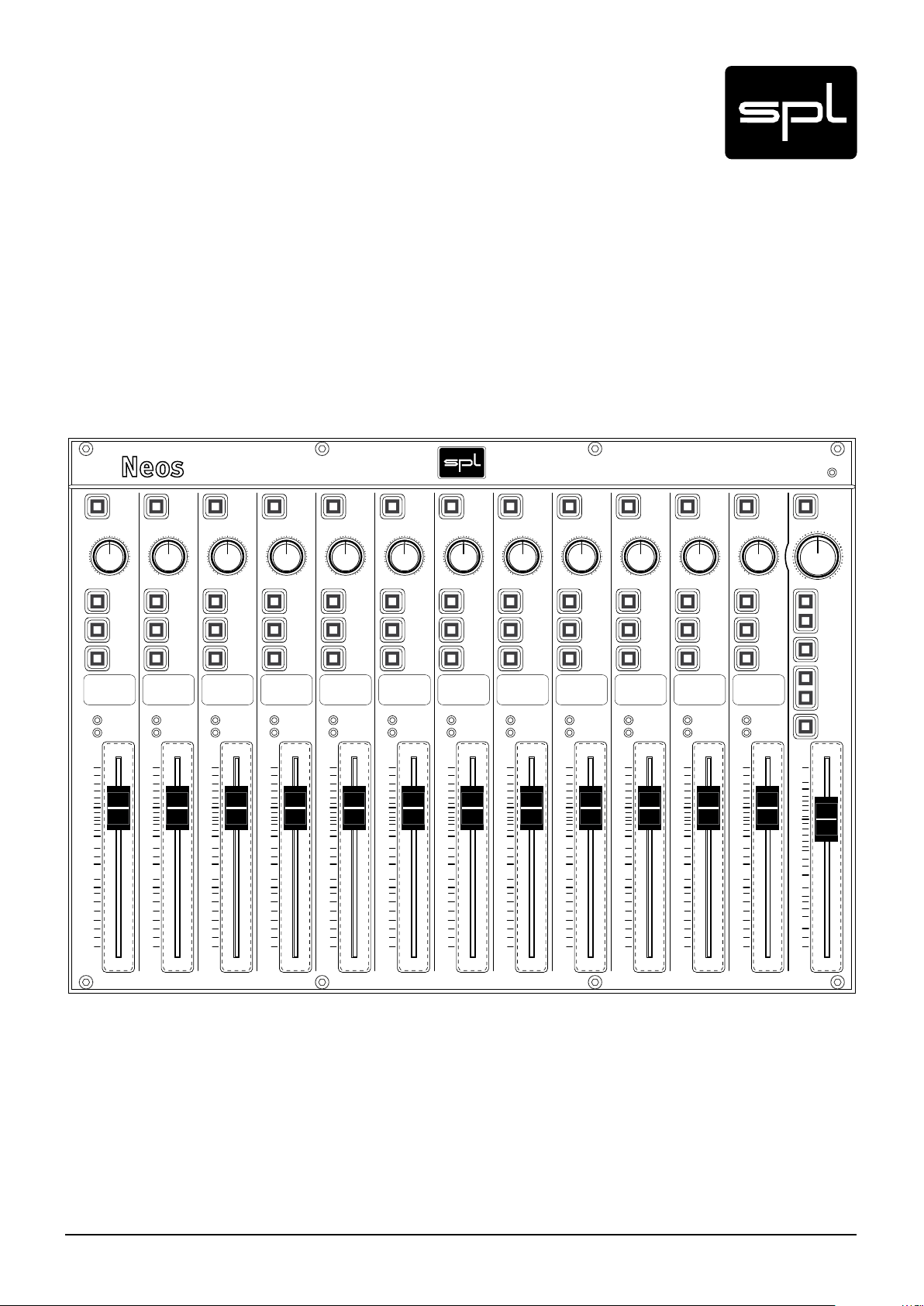
Neos
Model 1010
120-Volt Summing and Monitoring Console
Page 2
Content
Manual Neos 4
Declaration of CE Conformity 4
Notes on Environmental Protection 4
Contact 4
Scope of Delivery and Packaging 5
Symbols and Notes 5
Introduction 6
The High Voltage Console 6
Concept 7
Features 7
Special Features 7
Special Technical Features 7
Important Security Advices 8
Placement 9
Rack Mounting 9
Placement Of The External Power Supply 9
Voltage Selector (External Power Supply) 9
Power connection and fuse 9
Hook Up 9
Power Connection 10
Signal Connections 10
On/Of f Switch 10
GND Lift 11
XLR Sockets 11
DB 25 Sockets 11
Balanced Connections 11
Unbalanced connections (TS and RCA connectors) 11
Rear Panel – Switches & Connections, Basics 11
Rear Panel – Power Wiring Diagram 12
Rear Panel – Signal Wiring Diagram 13
Rear Panel 14
Inputs 1-8, 9-16, 17-24 14
Slave (additional input for additional Neos consoles) 14
Ins. Return (Insert Return) 14
Tape Rt. (Tape Return) 15
Rec Out
(Recording Output) 15
Monitor A and Monitor B 15
Alt. Out
(Alternative Output) 15
Ins. Send (Insert Send) 15
Metering 15
2
Neos
Page 3

Operation 16
Overview 16
Control Elements Input Path 16
Mono 16
Pan 17
Cut 17
To Monitor Only 17
Solo 17
Label Field 17
SIG LEDs 17
Fader 17
Control Elements Master Path 18
Mon B 18
Monitor 18
Monitoring with the Neos 18
Calibration 18
Mute 18
Dim 19
Mono 19
Tape Return 19
Master Insert 19
Bend 19
Fader 19
Content
DAW-Integration 20
Integration Examples and Channel Assignment 20
Specifications 21
Inputs & Outputs 21
Measurements 21
Power Supply 21
Dimensions and Weight 21
Dimensions and Weight External Power Supply 21
Copy Master Recall Settings 22
Block Diagram 23
Mounting Dimensions 24
Dimensions and Weight 24
Mounting Angles 25
Neos
3
Page 4
Manual Neos
Model 1010
Version 1.0 – 6/2011
Developer: Wolfgang Neumann
This manual contains a description of the product. It in no way represents a guarantee of
particular characteristics or results of use. The information in this document has been carefully compiled and verified and, unless otherwise stated or agreed upon, correctly describes
the product at the time of packaging with this document.
Sound Performance Lab (SPL) continuously strives to improve its products and reserves the
right to modify the product described in this manual at any time without prior notice.
© 2011 SPL electronics GmbH. All rights reserved. This document is the property of SPL and
may not be copied or reproduced in any manner, in part or fully, without prior authorization by
SPL. Names of other companies and their produc ts are trademarks of their re spe ctive owners.
Declaration of CE Conformity
The construction of the Neos, Model 1010, is in compliance with the standards
and regulations of the European Community.
Notes on Environmental Protection
At the end of its operating life, this product must not be disposed of with regular
household waste but must be returned to a collection point for the recycling of
electrical and electronic equipment. The wheelie bin symbol on the product,
user‘s manual and packaging indicates that. The materials can be re-used in
accordance with their markings. Through re-use, recycling of raw materials, or other forms
of recycling of old products, you are making an important contribution to the protection of
our environment. Your local administrative office can advise you of the responsible waste
disposal point. WEEE Registration: 973 349 88.
Contact
SPL electronics GmbH
Sohlweg 80, 41372 Niederkruechten, Germany
Phone +49 (0) 21 63 98 34 0, Fax +49 (0) 21 63 98 34 20
E-Mail: info@spl.info, Website: spl.info
4
Neos
Page 5
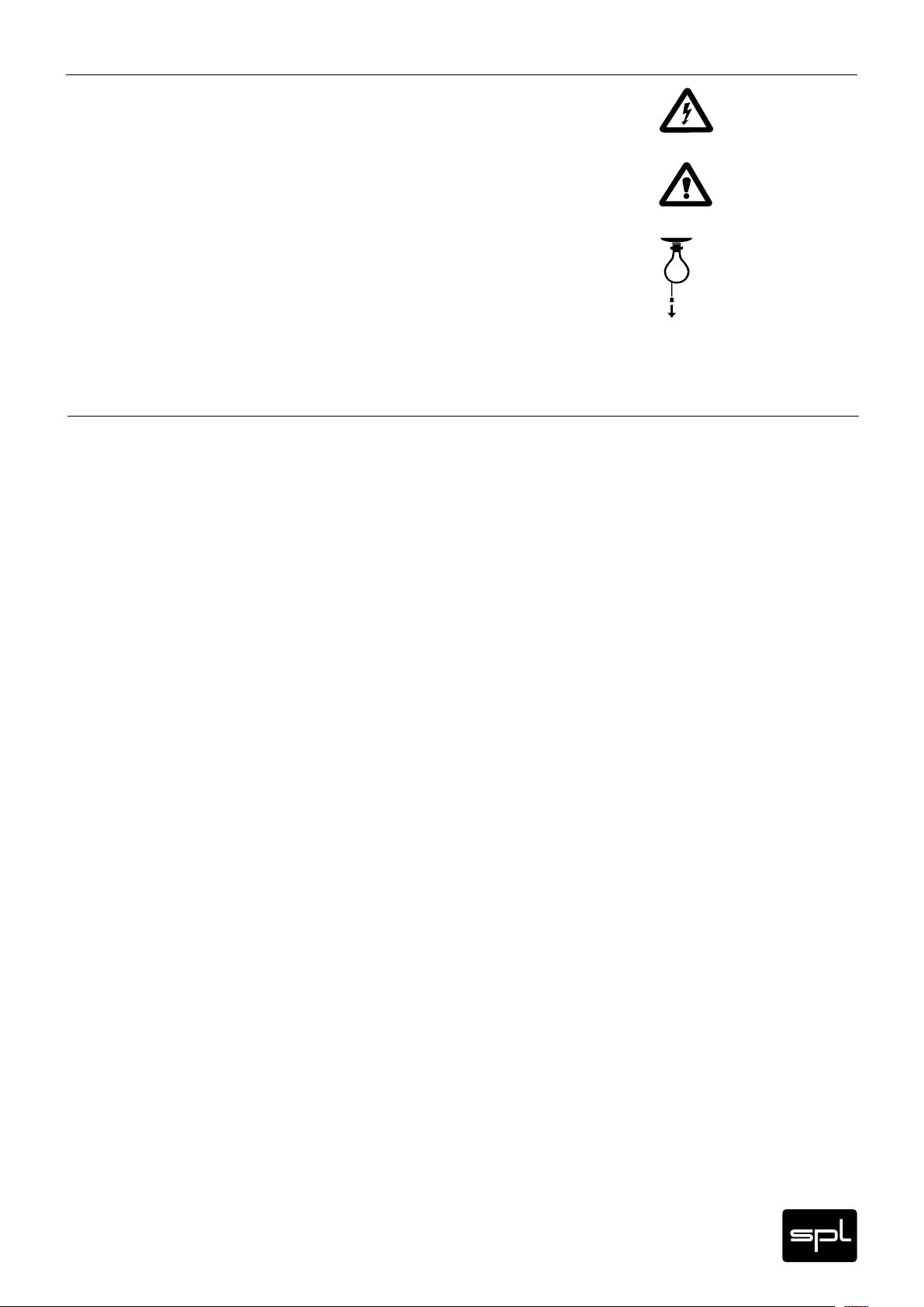
IN THIS MANUAL A LIGHTNING SYMBOL WITHIN A TRIANGLE WARNS YOU ABOUT THE
POTENTIAL FOR DANGEROUS ELECTRICAL SHOCKS – WHICH CAN ALSO OCCUR EVEN AFTER
THE MACHINE HAS BEEN DISCONNECTED FROM A POWER SOURCE.
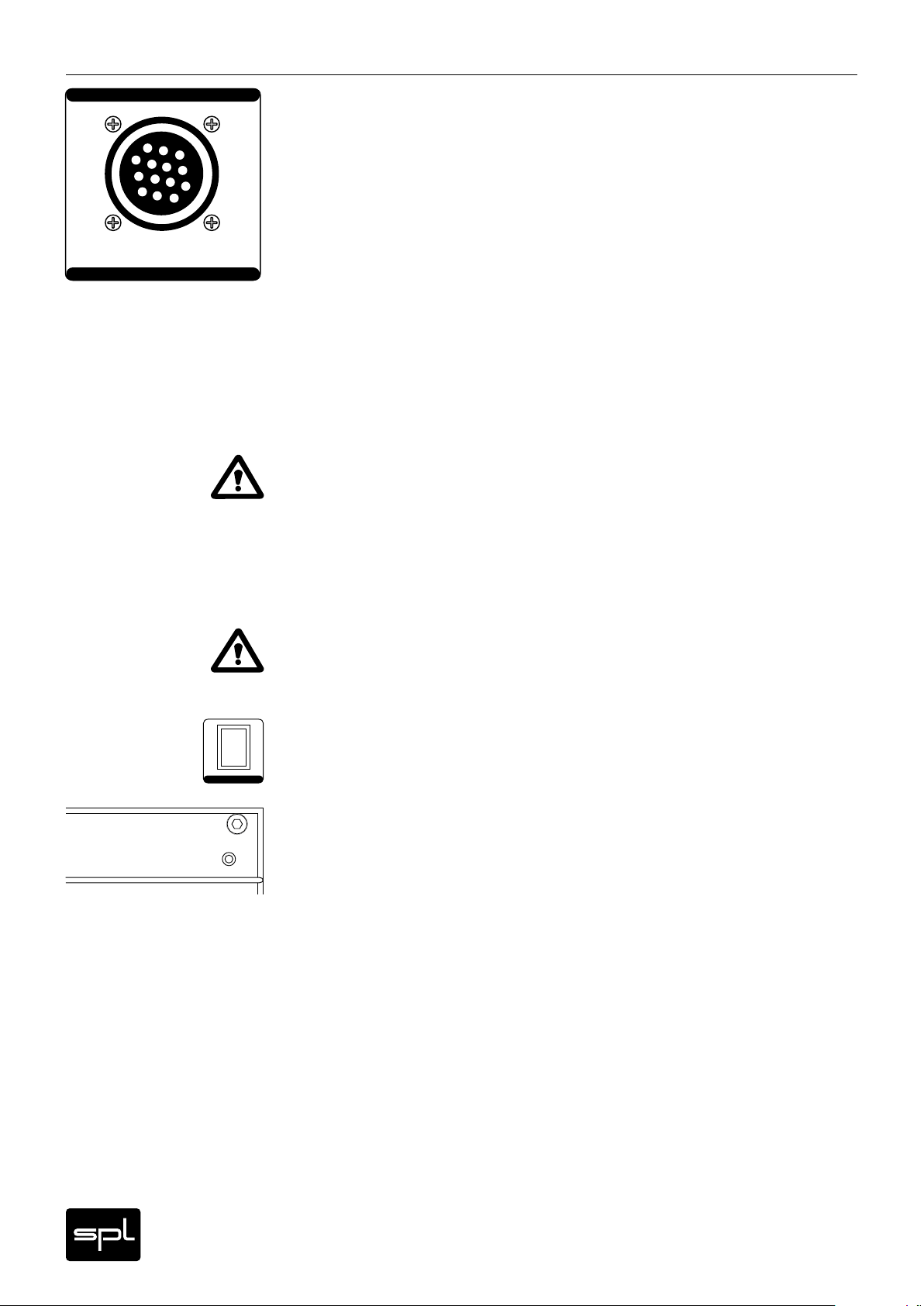
AN EXCLAMATION MARK (!) WITHIN A TRIANGLE IS INTENDED TO MAKE YOU AWARE OF
IMPORTANT OPERATIONAL ADVICE AND/OR WARNINGS THAT MUST BE FOLLOWED. BE
ESPECIALLY ATTENTIVE TO THESE AND ALWAYS FOLLOW THE ADVICE THE Y GIVE.
The symbol of a lamp directs your attention to explanations of important functions or applications.
Attention: Do not attempt any alterations to this machine without the approval or supervision
of SPL electronics GmbH. Doing so could nullif y completely any and all of your warrant y/guarantee rights and claims to user support.
Scope of Delivery and Packaging
The scope of delivery comprises the Neos console, 19" rack-mounting side brackets, the
external power supply with fixed cable for connection to the Neos, the external power
supply’s power cord, the guarantee card and this manual.
Please keep the original packaging. In case of a service procedure the original packaging
ensures a safe transport. It also serves as a safe packaging for your own transports if you do
not use special transportation cases.
Symbols and Notes
Neos
5
Page 6

Introduction
The High Voltage Console
Shortly after the turn of the millennium, SPL laid down new foundations for the improvement
of analog audio signal processing. Thanks to new components, circuitries and manufacturing
methods, we were able to increase the operating voltage enormously. Up to then, average
operating voltage ranged form 30 to 36 volts (+/- 15 or 18 volts, considering that voltage
supply is symmetrical). Maximum operating voltages reached 60 volts (+/- 30 volts). At the
core of our new technology are the handmade OP-amps that operate at 120 volts (+/- 60 volts),
which means that we have in fact doubled the highest levels ever reached until then.
The first products to integrate the 120-volt technology were exclusive, handmade custom solutions for major mastering studios. At the time, music production had already been uprooted
by digital technology and the changes it brought with itself in terms of outfitting and workflow in music studios. Coincidentally, a new „mastering“ sector had already been established
— both in terms of the actual process and the gear in studios. If traditional recording and
mixing studios were on their way to digitalization, the most sophisticated mastering studios
were and have always been keen on analog technology, including high-quality signal processors that can still make a difference compared to the widely available software solutions. But
also technically demanding requirements such as superior sounding and designed switching
and monitoring consoles were among the products we were able to offer. While analog technology was being heralded as dead, SPL was decisively going in the opposite direction: we
were able to deliver analog products of the highest quality whose performance surpassed all
previous specifications — regardless of whether it was in the analog or digital realm.
In the last decade we have been able to keep up with the rapidly evolving developments in
digital technology while pushing further our analog products. It was imperative to work on the
foundations of the products‘ performance. Thus, if we consider that the basis of every circuit
is directly related to a voltage/performance ratio, the operating voltage is crucial for the
performance of any circuit. Given that audio technology is conceived to translate sound into
voltage, doubling the formerly highest operating voltage available results in a great improvement, specially with regard to signal dynamics and the way they are processed. Technically
speaking, a wider dynamic range also means that the gap between the actual signal and other
undesired signals, such as noise and distortion, is larger — in the case of the Neos console,
for example, this results in not hearing any noises at all, regardless of the situation.
Our measurements reveal the improvements the 120-volt technology offers in comparison to
standard solutions (see „Technical Specifications“ on page 21). All these advantages are due
to the oversized signal traces, the rigorous selection of every single element and, of course,
the handmade components that contain no unnecessary audio processing parts (which are
very common in mass-produced operation amplifiers). But the technical specifications and
design say very little about the actual sound of an audio equipment. At the end of the day, an
audio device has to prove itself in use in the hands of sound engineers and musicians. We can
state with great satisfaction that our solution not only prevailed — ever since their introduction, our 120-volt products have passed all tests and proven wor thy of the best.
The Neos is the first summing console based on the 120-volt technology. The basic concept
behind it was to combine essential summing capabilities, including faders and panorama
controls, with a complete and practical monitoring section — all in a compact design.
Accordingly, it fulf ills the highest expectations regarding sound quality in mixing and monitoring situations. Thus, the Neos was conceived with sound engineers that set great importance on artistic and musical production in mind and whose workflow does not rely primarily
on undo and preset options. Nevertheless, the compact Neos can integrate seamlessly in
computer-based environments providing the characteristic high-quality sound and handling
of analog devices.
6
Neos
Page 7
Concept
• 24 channel summing console with faders and panorama controls
• Ideal for DAW-based studios with emphasis on audio quality. .
Features
• Input path with 100-mm ALPS faders, Pan controls, Mono, Cut, Solo, and “To Monitor
Only” push buttons, signal LEDs
• Master path with 100-mm ALPS faders, Insert s, Bend func tion (Limiting)
• Comprehensive monitoring section with Volume control, Tape Mix (DAW return), as well
as Mute, Dim and Mono push buttons
• Input: three eight-channel DB25 connectors (balanced, TASCAM standard); balanced
XLR connectors: Slave, Insert Return, Tape Return
• Output connectors (balanced XLR): Recording Out, Monitor A and Monitor B,
• Output connectors (unbalanced XLR): Alternative Out, Insert Send, Metering
Special Features
• Ultimate Mix and Monitoring Quality
Introduction
• Compact design: 19"/7U
• Cascadable
• Hand made in Germany
Special Technical Features
• Unique 120-volt operating voltage. In comparison with common production mixers, the
Neos mixing and monitoring console uses four times as much operating voltage. A higher
voltage results in better performance: over 30 dB of headroom at the input, more than
122 dB of dynamic range, 92 dB signal-to-noise ratio over all channels.
• At the core of the 120-volt technology are our handmade, discrete op-amps with 116
dB signal-to-noise ratio and 34 dB of headroom. The 150 dB dynamic range covers a
frequency range of up to 200 kHz. These key figures are way beyond the demands of
current PCM digital formats with 24 bit/192 kHz sample rates and DSD digital formats
with 1 bit and 256 fs. It is not expected for digital technology to evolve so much in the
foreseeable future as to make the Neos a bottleneck in the signal processing path.
• All selected components for each unit are matched at the pre-production stage
• Important switching functions are performed via sealed relays
• Oversized signal traces, generous PCB layout for greater trace separation, star ground
scheme, linear power supply
Neos
7
Page 8
Important Security Advices
Please note and retain this manual. Carefully read and follow all of the safety and operating
instructions before you use the machine. Be doubly careful to follow all warnings and special
safety instructions noted in this manual and on the unit.
Connections: Only use the connections as described. Other connections can lead to health
risks and equipment damage.
Water and humidity: Do not use this machine anywhere near water (for example near a wash
basin or bath, in a damp cellar, near swimming pools, or the like). In such cases there is an
extremely high risk of fatal elec trical shocks!
Insertion of foreign objects or fluids: Never allow a foreign object through any of the
machine‘s chassis openings. You can easily come into contact with dangerous voltage or
cause a damaging short circuit. Never allow any fluids to be spilled or sprayed on the machine.
Such actions can lead to dangerous electrical shocks or fire!
Opening the unit: Do not open the machine housing, as there is great risk you will damage the
machine, or – even af ter being disconnected – you may receive a dangerous electrical shock!
Electrical power: Run this machine only from power sources which can provide proper power
in the range from 100 to 250 volts. When in doubt about a source, contact your dealer or a
professional electrician. To be sure you have isolated the machine, do so by disconnecting all
power and signal connections. Be sure that the power supply plug is always accessible. When
not using the machine for a longer period, make sure to unplug it from your wall power socket
and from the guitar amp.
Cord protection: Make sure that your power and guitar amplifier signal cords are arranged
to avoid being stepped on or any kind of crimping and damage related to such event. Do not
allow any equipment or furniture to crimp the cords.
Power connection overloads: Avoid any kind of overload in connections to wall sockets,
extension or splitter power cords, or to signal inputs. Always keep manufacturer warnings
and instructions in mind. Overloads create fire hazards and risk of dangerous shocks!
Lightning: Before thunderstorms or other severe weather, disconnect the machine from wall
power (but to avoid life threatening lightning strikes, not during a storm). Similarly, before
any severe weather, disconnect all the power connections of other machines and antenna and
phone/network cables which may be interconnected so that no lightning damage or overload
results from such secondary connections.
Air circulation: Chassis openings offer ventilation and serve to protect the machine from overheating. Never cover or otherwise close off these openings. Never place the machine on a soft
surface (carpet, sofa, etc.). Make sure to provide for a mounting space of 4-5 cm/2 inches to
the sides and top of the unit when mounting the unit in racks or on cabinets.
Controls and switches: Operate the controls and switches only as described in the manual.
Incorrect adjustments outside safe parameters can lead to damage and unnecessary repair
costs. Never use the switches or level controls to effect excessive or extreme changes.
Repairs: Unplug the unit from all power and signal connections and immediately contact a
qualified technician when you think repairs are needed – or when moisture or foreign objects
may accidentally have gotten in to the housing, or in cases when the machine may have fallen
and shows any sign of having been damaged. This also applies to any situation in which the
unit has not been subjected to any of these unusual circumstances but still is not functioning
normally or its performance is substantially altered. In cases of damage to the power supply
and cord, first consider turning off the main circuit breaker before unplugging the power cord.
Replacement/substitute parts: Be sure that any service technician uses original replacement
parts or those with identical specifications as the originals. Incorrectly substituted parts can
lead to fire, electrical shock, or other dangers, including further equipment damage.
Safety inspection: Be sure always to ask a service technician to conduct a thorough safety
check and ensure that the state of the repaired machine is in all respects up to factory standards.
Cleaning: In cleaning, do not use any solvents, as these can damage the chassis finish. Use
a clean, dry cloth (if necessary, with an acid-free cleaning oil). Disconnect the machine from
your power source before cleaning.
8
Neos
Page 9

Placement
Place the unit on a level and stable surface or mount it into dedicated rack frames. The unit’s
enclosure is EMC-safe and effectively shielded against HF interference. Nonetheless, you
should carefully consider where you place the unit to avoid electrical disturbances. It should
be positioned so that you can easily reach it, but there are other considerations. Try not to
place it near heat sources or in direct sunlight, and avoid exposure to vibrations, dust, heat,
cold or moisture. It should also be kept away from transformers, motors, power amplifiers
and digital processors.
Rack Mounting
Be sure that both above and below the machine you maintain a distance of 4-5 cm/2 inches
in order to eliminate electromagnetic or high frequency interference from other equipment.
Moreover, this will ensure adequate air circulation to prevent overheating. Do NOT locate
other machines that produce excessive heat below the unit. The rear side of the machine
should be properly supported – especially when transport is involved.
Placement Of The External Power Supply
Do not place the external power supply on top of the Neos and vice versa. Place the external
power supply on a level and stable surface only. We recommend a distance of at least 50
cm/20 inches to avoid any interferences between the external power supply and the Neos
frame or other devices.
Hook Up
Choose a place that is easily accessible so that you can switch off the external power supply
quickly in case of an emergency.
Please mind the notes under “Power Connection” and “On And Off” on the next page.
Voltage Selector (External Power Supply)
Be very careful to check that the voltage selection switch is set to the correct local line
voltage position before using the unit (230 V position: 220-240 V/50 Hz, 115 V position:
110-120 V/60 Hz)! When in doubt about a source, contact your dealer or a professional electrician.
BEFORE you connect electrical power make sure that the VOLTAGE selector setting reflects
the correct local power line voltage.
Power connection and fuse
Connect the power cord to the MAINS INPUT socket of the external power supply. Transformer,
power cord and case connection conform to VDE, UL and CSA requirements.
The fuse is accessible from outside and placed right behind the flap right from the socket.
Fuse ratings are 2 A slow blow (
230
volts) or 4 A slow blow (
115
volts).
230V~50Hz | 2A slow
115V~60Hz | 4A slow
Use slow blow fuse.
VOLTAGE | FUSE
Neos
9
Page 10
Hook Up
CONNECT TO EXTERNAL PSU
CONNECT TO EXTERNAL PSU
Power Connection
The Neos is fed through the external power supply. Before connecting the power supply
always make sure that the position of the voltage selector on the back of the RackPack corresponds to the voltage of your local power supply (115V position: 110-120V, 230 V position:
220-240V). In case of doubt please ask your dealer, a professional electrician or your local
power supplier.
Before you connect the external power supply to the wall socket please switch its POWER
button to OFF. Also turn off all devices that you may have already connected to the RackPack.
If signal or power connections are changed in the future, always switch off power before.
Before you connect the external power supply to the wall socket you should connect it to the
Neos (see illustration on page 12). The cable fixed to the external power supply with the multipin connector on the other end is made to connect to the Neos. It is not possible to connect it
incorrectly; place the groove at the end of the plug on the spring at the socket on the Neos and
tighten the screw.
After connecting the external power supply to the Neos and selecting the correct voltage on
the external power supply, connect the power supply to the wall socket and then turn on the
Neos with the POWER switch.
IMPORTANT: Never disconnect the external power supply from the Neos while the power is
switched on. Always turn the external power supply off first and then wait approximately
one minute to allow for any residual current to discharge. Now you may disconnect the multipin connector. Mind that residual current can damage the unit if you do not follow this procedure!
120 Volts Analog
Pure Audio Performance
POWER
W
O
P
Please read and follow all security advices on pages 4 and 5.
Signal Connections
IMPORTANT: Before first connecting any other equipment – and in all other cases where you
are connecting cables with or from other sources – you should be sure to shut the unit and
all machines to be connected off (external power supply). Otherwise you risk to damage the
unit, connected gear or your ears.
On/Off Switch
With the external power supply’s Power switch you activate and deactivate the Neos, operational status is confirmed by the blue Power LED on the Neos front panel (top right corner).
On And Off
E
R
In switching on and off, you do not need to follow any particular sequence with connected
devices in the periphery of the Neos. There is, however, the general rule for a chain of devices
in the audio processing to always turn on power amplifiers last and to turn them off first.
If specified sufficiently you can also switch the external power supply on and off through a
multiway connector or other main switches.
10
Neos
Page 11
Rear Panel – Switches & Connections, Basics
GND Lift
The rear panel GND LIFT switch eliminates hum by separating the internal ground from the
unit’s housing ground. Hum can, for example, result when this unit’s housing has a common
ground connection with other devices that might have a different ground potential. The
switch is usually deactivated to retain the shielding of the housing.
XLR Sockets
All signal connections are made via balanced or unbalanced XLR sockets. Pin wiring is shown
in the diagram below. Inputs are always female and accept male connectors; outputs are
always male. All in all, a comprehensible principle.
DB 25 Sockets
All 24 inputs are distributed on three eight-channel, female DB25 sockets. The connectors are
balanced and adhere to the Tascam standard (details on page 12).
Balanced Connections
In balanced connections a reference signal with reversed polarity is transmitted additionally
to the audio signal through a second wire. The ground signal is routed separately through
a third wire. Input and output stages are drivers and receivers, and the receiving stage can
suppress possible interferences by subtracting the difference between audio and reference
signal. The Neos employs electronic balancing stages (no transformers).
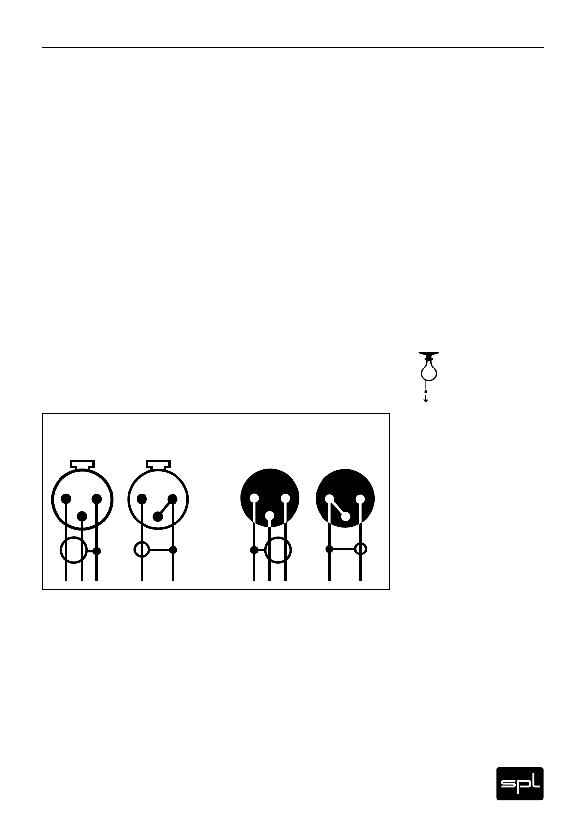
Unbalanced connections (TS and RCA connectors)
Unbalanced connections from and to RCA or 1/4" TS sockets can be made without adaptors to
the balanced XLR sockets. The correct wiring is important. The diagram shows the pin conf iguration of the XLR sockets and how to correctly connect them for unbalanced connections:
Input
balanced
2
Connections to RCA sockets are always unbalanced, a wiring to jack connectors can be both
balanced (1/4" TRS/stereo jack) or unbalanced (1/4" TS/mono jack). We recommend to use
individually configured cables from XLR to RCA or jack sockets instead of adaptors. You can
get cables in any needed configuration from audio dealers. With the diagram above, the
dealer can ensure to provide the appropriate cable for your application.
1
3
unbalanced
2
1
3
1=GND
2= hot (+)
3= cold (-)
balanced
1
2
3
Output
unbalanced
1
2
3
Neos
11
Page 12

Rear Panel – Power Wiring Diagram
L RREC OUT
INPUTS 1 – 8
DB 25 CONNEC TOR WIRING
DB25 COMPLY WITH TASCA M STANDARD.
PLEASE REFE R TO MANUAL FOR DETAILS.
1 = GND
SLAVE CONN ECTOR WIRING
INPUTS 9 – 16
MONITOR BUS: 4 = HOT (+) | 5 = COLD (–)
RECORDING BUS: 2 = HOT (+) | 3 = COLD (–)
INPUTS 17 – 24
LR INS. RETURNLR INS. SENDLR METERINGLR SLAVE
XLR CONNEC TOR WIRING
Neos – Model 1010
ALT. OUT XLR (UNBAL.):
1 = GND | 2 = HOT (+) | 3 = GND
XLR (BAL.): 1 = GND | 2 = HOT (+) | 3 = COLD (–)
Serial Number
www.spl.info
Made in Ger many
L RTAPE Rt.
L RMONITOR A
L RMONITOR B
R LREC OUT
R LTAPE Rt.
R LMONITOR A
R LMONITOR B
NEVER disconnect the external power supply
BEFORE switching on the external power supply,
connect the external power supply and the Neos
with the multi-pin power cord fixed to the external power supply.
from the Neos while the power supply
is still switched on.
First switch off the external power supply
and wait at least one minute before disconnecting.
3
Otherwise residual currents can cause serious damages!
CONNECT TO EXTERNAL PSU
L RALT. OUT
2
WARNING
THIS EQUIPMENT MUST BE E ARTHED.
TO REDUCE RISK OF FIRE OR EL ECTRIC SHOCK.
DO NOT EXPOS E THIS UNIT RAIN OR MOIS TURE.
DISCONNECT MA INS BEFORE REMOVING COVER.
GND LIFT
GND
CAUTION
RISK OF ELECTRIC SHOCK
DO NOT OPEN
GND LIFT
GND LIFT
AVIS: RISQUE DE CHOC ÉLEC TRIQUE – NE PAS OUVRIR
R LALT. OUT
GND LIFT
The rear panel GND lift switches
eliminate hum by separating
the internal ground from the
unit’s housing ground.
If hum occurs, press the
switches to activate GND lift.
CONNECT POWER CORD
IMPORTANT:
TO NEOS BEFORE SWITCHING ON POWER!
TO REDUCE RISK OF FIRE OR ELECTRIC SHOCK DO
BEFORE REMOVING COVER. THIS EQUIPMENT MUST BE EARTHED.
NOT EXPOSE THIS UNIT TO RAIN OR MOISTURE. DISCONNECT MAINS
WARNING:
spl.info
NEOS
Power Supply Unit
POWER OUTPUT TO AUDIO UNIT
Model 1010-P
MADE IN GERMANY
POWER
230V~50Hz | 2A slow
SERIAL NUMBER
Before you use the Neos, make sure that this voltage selector switch setting reflects
the correct local power line voltage (115V position: 110-120V, 230 V position: 220-240V).
In the drawing above the 230 V position is selected.
VOLTAGE | FUSE GND LIFT
Use slow blow fuse.
115V~60Hz | 4A slow
1
CAUTION
DO NOT OPEN
MAINS INPUT
RISK OF ELECTRIC SHOCK
AVIS: RISQUE DE CHOC ÉLECTRIQUE - NE PAS OUVRIR
12
CONNECT TO EXTERNAL PSU
Neos
Page 13

Pin Wiring XLR Outputs:
1=GND, 2=hot (+), 3=cold (-)
3
21
Pin Wiring XLR Inputs:
1=GND, 2=hot (+), 3=cold (-)
3
2
1
CONNECT TO EXTERNAL PSU
GND LIFT
Rear Panel – Signal Wiring Diagram
Second Neos: connect
with SPL cable only!
CONNECT TO EXTERNAL PSU
AVIS: RISQUE DE CHOC ÉLEC TRIQUE – NE PAS OUVRIR
DO NOT OPEN
RISK OF ELECTRIC SHOCK
GND LIFT
GND
GND LIFT
CAUTION
GND LIFT
Display
Level
(e. g. Headphone Amplifier)
Alternative Output
unbalanced balanced balanced
(e. g. Compressor, EQ)
Sum Processing
balancedunbalanced balanced
R LALT. OUT
DISCONNECT MA INS BEFORE REMOVING COVER.
DO NOT EXPOS E THIS UNIT RAIN OR MOIS TURE.
TO REDUCE RISK OF FIRE OR EL ECTRIC SHOCK.
THIS EQUIPMENT MUST BE E ARTHED.
(DAW/DA converter, Tape)
Listen to recorded signals
balancedbalanced
(DAW/AD converter, Tape)
Record summed signal
(e. g. Near Field)
Speakers
(e. g. Full Range)
Speakers
R LMONITOR B
R LMONITOR A
R LTAPE Rt.
R LREC OUT
L RALT. OUT
L RMONITOR B
Made in Germ any
L RMONITOR A
L RTAPE Rt.
1 = GND | 2 = HOT (+) | 3 = GND
Neos – Model 1010
www.spl.info
Serial Number
XLR (BAL.): 1 = GND | 2 = HOT (+) | 3 = COLD (–)
ALT. OUT XLR (UNBAL.):
WARNING
LR INS. RETURNLR INS. SENDLR METERINGLR SLAVE
INPUTS 17 – 24
(3 x eight-channel DB25)
Input Channels 1-24
RECORDING BUS: 2 = HOT (+) | 3 = COLD (–)
MONITOR BUS: 4 = HOT (+) | 5 = COLD (–)
SLAVE CONN ECTOR WIRING
INPUTS 9 – 16
XLR CONNEC TOR WIRING
INPUTS 1 – 8
1 = GND
PLEASE REFE R TO MANUAL FOR DETAILS.
DB25 COMPLY WITH TASCA M STANDARD.
DB 25 CONNEC TOR WIRING
Neos
L RREC OUT
13
Page 14

Rear Panel
Inputs
INPUTS 1 – 8
INPUTS 9 – 16
INPUTS 17 – 24
Inputs 1-8, 9-16, 17-24
The balanced DB25 input connectors are meant to connect the different signal sources. The
Neos’ 24 inputs are divided into three DB25 connectors. You can get ready-made XLR or jack
snakes in your local specialized store.
The maximum input level of the DB25 inputs is ›30dBu. The connectors are balanced and
adhere to the Tascam standard according to the following pin assignment:
1 2 3 4 5 6 7 8
GCHGCHGCHGCHGCHGCHGCHGCH
13
25
G=GROUND (GND), C=COLD (-), H=HOT (+)
LR SLAVE
Slave (additional input for additional Neos consoles)
The Slave input allows the connection of additional Neos consoles. When two consoles are
interconnected you have 48 channels at your disposal. You can connect an unlimited number
of Neos with each other. The connector is based on a special 5-pin XLR format.
1
14
IMPORTANT: the interconnection of Neos consoles can only be established via a custommade cable manufactured by SPL under request.
When two or more Neos are interconnected, the stereo output signal is summed, so instead
of summing 24-in-2 channels you have 48 (or more) channels summed into one stereo signal.
The connection has no set direction, which means the sum signal of all channels is always
present in the outputs (Rec Out, Monitor A and B, and Alt Out) of all interconnected Neos.
Therefore, all recording media should be normally connected to only one Neos — but there
are many connection possibilities open with all other units involved.
The slave function applies only to the sum of the stereo output signals pre-Master path.
Generally speaking, the Neos considered the “Master” will be the one to which the monitor
speakers are connected. All switching functions of the Master path can be applied to the
totality of channels which have been summed. All switching functions of a single input path
apply only to the corresponding Neos unit. In this respect, each Neos is to be considered and
operated independently. For example, the Solo function of any input path: to listen to an
isolated channel you have to depress the corresponding Solo switch; however, the channels
of the other interconnected Neos consoles are not muted. A practical solution for this would
be to activate a solo function in your DAW that would affect all channels.
Other interesting possibilities arise when two or more Neos units are connected to the monitoring system along with other gear. There are many individual solutions available, which we
will be more than happy to discuss with you.
LR INS. RETURN
Ins. Return (Insert Return)
14
Use the Master Insert loop to add external signal processors to the Neos’ internal processing.
Connect the Master Insert’s returning signal, i.e. the output signal of the external processor, to
the Ins. Return input.
The maximum level these unbalanced inputs can handle is › 24 dBu. To activate the Insert
function use the Master Insert push button in the Master path (for more information see
Control Elements, Master Inser t, on page 19).
Neos
Page 15

Outputs
Tape Rt. (Tape Return)
The Tape Return function allows you to bring back the recorded signal to the Neos in order to
listen to it. Connect to the Tape Rt. input the output signal of the DA converter or tape machine.
The maximum level these balanced inputs can handle is › 30 dBu. To activate the input use the
Tape Return push button in the Master path (for more information see Control Elements, Tape
Return, on page 19).
Rear Panel
L RTAPE Rt.
R LTAPE Rt.
Rec Out (Recording Output)
The output signal of the Neos is available at the Rec Out so you can record the final mixdown.
This where the AD and tape machines ought to be connected.
The maximum level delivered by the Rec Outputs is › 24 dBu.
Monitor A and Monitor B
The balanced Monitor A and Monitor B outputs are meant to feed power amps or active
monitor speakers. The two separate outputs allow the use of two different monitor speakers.
Generally speaking, Monitor A is always active. To switch to Monitor B use the Mon B push
button on the Maser path.
The maximum level delivered by the Monitor B output is › 24 dBu.
Alt. Out (Alternative Output)
At these outputs you have a copy of the Rec Out signal. The Alternative Outputs can be used
to connect a headphones preamplifier.
L RREC OUT
R LREC OUT
L RMONITOR A
R LMONITOR A
L RALT. OUT
The maximum level delivered by the unbalanced Alt Outputs is › 24 dBu.
Ins. Send (Insert Send)
Use the Master Insert loop to add external signal processors to the Neos’ internal processing.
Connect the inputs of external signal processors to the unbalanced Ins. Send outputs. To activate the Inser t function use the Master Insert push button in the Master path (for more information see Control Elements, Master Insert, on page 19).
The Send outputs deliver › 24 dBu.
Metering
Use the unbalanced Metering output to connect VU or PPM meters in order to monitor the
signal of the Rec. Outputs. The nominal level is calibrated to 0 dB. The maximum level delivered by the Metering Outputs is › 24 dBu.
R LALT. OUT
LR INS. SEND
LR METERING
Neos
15
Page 16

Operation
24|2 Mixing Cons ole
Overview
120 Volts Analog
Pure Audio Performan ce
W
E
R
O
P
MONO
N
A
P
C
R
L
CUT
To Monitor
Only
SOLO
SIG SIG SIG SIG SIG SIG SIG SIG SIG SIG SIG SIG
1
2
dB
+6
5
4
3
2
0
-2
-4
-5
-6
-8
-10
-12
-15
-18
-20
-24
-28
-36
-40
-50
-
∞
MONO
N
A
P
C
R
L
CUT
To Monitor
Only
SOLO
3
4
dB
+6
5
4
3
2
0
-2
-4
-5
-6
-8
-10
-12
-15
-18
-20
-24
-28
-36
-40
-50
-
∞
MONO
N
A
P
C
R
L
CUT
To Monitor
Only
SOLO
5
6
dB
+6
5
4
3
2
0
-2
-4
-5
-6
-8
-10
-12
-15
-18
-20
-24
-28
-36
-40
-50
-
∞
MONO
N
A
P
C
R
L
CUT
To Monitor
Only
SOLO
7
8
dB
+6
5
4
3
2
0
-2
-4
-5
-6
-8
-10
-12
-15
-18
-20
-24
-28
-36
-40
-50
-
∞
MONO
N
A
P
C
R
L
CUT
To Monitor
Only
SOLO
9
10
dB
+6
5
4
3
2
0
-2
-4
-5
-6
-8
-10
-12
-15
-18
-20
-24
-28
-36
-40
-50
-
∞
MONO
N
A
P
C
R
L
CUT
To Monitor
Only
SOLO
11
12
dB
+6
5
4
3
2
0
-2
-4
-5
-6
-8
-10
-12
-15
-18
-20
-24
-28
-36
-40
-50
-
∞
MONO
N
A
P
C
R
L
CUT
To Monitor
Only
SOLO
13
14
dB
+6
5
4
3
2
0
-2
-4
-5
-6
-8
-10
-12
-15
-18
-20
-24
-28
-36
-40
-50
-
∞
MONO
N
A
P
C
R
L
CUT
To Monitor
Only
SOLO
15
16
dB
+6
5
4
3
2
0
-2
-4
-5
-6
-8
-10
-12
-15
-18
-20
-24
-28
-36
-40
-50
-
∞
MONO
N
A
P
C
R
L
CUT
To Monitor
Only
SOLO
17
18
dB
+6
5
4
3
2
0
-2
-4
-5
-6
-8
-10
-12
-15
-18
-20
-24
-28
-36
-40
-50
-
∞
MONO
N
A
P
C
R
L
CUT
To Monitor
Only
SOLO
19
20
dB
+6
5
4
3
2
0
-2
-4
-5
-6
-8
-10
-12
-15
-18
-20
-24
-28
-36
-40
-50
-
∞
MONO
N
A
P
C
R
L
CUT
To Monitor
Only
SOLO
21
22
dB
+6
5
4
3
2
0
-2
-4
-5
-6
-8
-10
-12
-15
-18
-20
-24
-28
-36
-40
-50
-
∞
A
P
C
L
dB dB
+6
5
4
3
2
0
-2
-4
-5
-6
-8
-10
-12
-15
-18
-20
-24
-28
-36
-40
-50
-
∞
MONO
N
R
CUT
To Monitor
Only
SOLO
23
24
MON B
I
T
N
O
O
R
M
0
1
-
-
8
2
1
-
-
6
6
1
-
-
4
8
1
-
6
2
-
0
3
-
8
3
-
1
2
2
-
-
0
1
3
4
5
6
4
-
6
0
6
-
+
0
7
8
-
MUTE
DIM
MONO
TAPE
RETURN
MASTER
INSERT
BEND
+8
7
6
5
3
2
0
-2
-4
-5
-6
-8
-10
-12
-15
-18
-20
-24
-28
-36
-46
-
∞
Model 1010
Overview
The control elements of the Neos console are distributed horizontally across the input paths
and Master path.
The Master path is on the far right. This section houses the processing functions and control
elements of the output signal, as well as all monitoring functions.
To the left are the twelve stereo input paths. In the input paths is where the level and
panorama settings, as well as some other functions, of the signals to be mixed is adjusted.
In principle there are only two different types of paths. Thus, it is almost absurd to even think
of a learning curve to actually start working with the Neos — instead, we could say there is
one single learning step, which is almost self-explanatory just by reading the names of the
functions involved.
Control Elements Input Path
MONO
Mono
The Neos offers 24 input channels in total. Two channels make up what we call an input path.
Input paths work generally in stereo. When working with mono signals (vocals, instruments
recorded on one single channel, etc.) you use only one of the channels of the input path.
Depress the Mono push button on the corresponding path to place the signal in the center of
the stereo panorama, instead of hard left. That way you can use the Pan control to place the
signal wherever you want in the stereo field.
Made in Germany
16
Neos
Page 17

Control Elements Input Path
Pan
Use the Pan control to place the signal in the stereo field of the sum signal. Both mono and
stereo signals can be placed continuously in the stereo field anywhere from hard left (L) to
center (C) and hard right (R).
N
A
P
C
R
L
Cut
Use the Cut push button to mute the input signal of the corresponding channel. The input
signal is withdrawn from the mix and therefore is not available anymore in the sum or monitor
signals.
To Monitor Only
Use this push button to assign the corresponding input path exclusively to the monitoring
bus. This function is based upon standard voltage circuitry with a max. I/O level of ‹20 dBu*.
To Monitor Only overrides the Cut function on the monitoring bus. If both push buttons are
engaged, the signal will be heard but not mixed. This can be very convenient, for example,
when you need to only play back a stereo signal.
Solo
The Solo push button mutes all other channels, i.e. the only channel that is heard is the one
with Solo engaged. The Solo function relates only to the monitor bus, it does not affect the
mix signal.
This function is based upon standard voltage circuitry with a max. I/O level of ‹20 dBu*.If you
activate several Solo buttons, you hear alle channels with active Solo button. Compared to
the usual play back, there are two main differences: The signal is always switched to mono,
and the Solo function is carried out in PFL mode (Pre Fader Listening). This means the signal
is routed to Solo before the fader with a fixed level. Faint signals are well audible, too – your
fader settings, eventually found after longer work, do not have to be altered.
CUT
To Monitor
Only
SOLO
Label Field
Use this space to label the channels any way you want. The easiest and most practical way
to label the channels is to use a pencil given that they are easily readable, do not hurt the
sur face and can be easily erased. If you prefer stickers, use removable ones or adhesive tape.
SIG LEDs
The Signal LEDs turn on when the input level surpasses -10 dBu. This allows checking whether
the feed signal is actually being sensed when using complex connections. On the other side, it
also allows you to monitor the signal level.
Fader
The faders are meant to control the signal level. Each fader controls both channels of a single
input path; when in mono mode this applies to the channel in use. The level ranges from +6dB
to -∞.
The ALPS fader with dust cover has a generous 100 mm travel. The fader control cur ve is
optimal for mixing applications and has been matched to the human hearing response, which
means it is not linear. The range with the smoothest and finest response ranges from 0 to
+6dB. But the range from 0 dB to around -15 dB also has a very high resolution.
* All other stages are capable of processing higher input levels (› 30 dB). If the stages of these
monitoring functions are overloaded, the recording and master monitoring signals are not
affected. Reduce the fader setting of the respective channel if necessary.
-
-10
-12
-15
-18
-20
-24
-28
-36
-40
-50
SIG
1
2
dB
+6
5
4
3
2
0
-2
-4
-5
-6
-8
∞
Neos
17
Page 18

Control Elements Master Path
MON B
Mon B
Use the Master path’s top-most push button to activate the Monitor B output. Monitor output
A will be muted. Usually you would have two different sets of monitor speakers connected.
With the Monitor B push button you can choose the set you want to listen to. However, you
can always connect a headphones preamp to one of the Monitor outputs. Take into account
that you should always calibrate both Monitor outputs to always have the same level — even
if you use headphones. In this last case, adjust the level so that when you set 0 dB in the
headphones preamp volume control and the Neos Monitor control you get the same sound
pressure level as you would with monitor speakers in the listening position. Apart from being
able to compare sound pressure levels between different monitor speakers, this also avoids
any unpleasant volume differences when switching from one monitoring set to the other.
Once you are done calibrating the headphones preamp, always adjust the volume level on the
Neos without modifying the preamp’s level control. Please refer to “Calibrate“ on this page.
Monitor
I
T
N
O
O
M
6
1
-
8
1
-
2
2
-
6
2
-
0
3
-
8
3
-
6
4
-
0
6
-
0
R
0
1
-
-
8
2
1
-
-
6
-
4
-
1
0
1
3
4
5
6
+
8
7
-
Use the Monitor control to set the listening volume. This control affects Monitor outputs
A and B. The potentiometer used is a “Big Blue” ALPS (RK27). This type of potentiometers
are well-known for their high overload capacity, even response and a very smooth rotation
with enough resistance but without being stiff. The Monitor control uses a relative dB scale
referenced to the input level. The 0 dB mark is approximately at the 2-o’clock position, which
means that when set to this position the input level is “as is” (the amplification factor is 1 or
“Unity gain”). The control range extends from -80 dB to +7 dB. The control’s sensitivity is
maximal at normal listening levels, due to a higher resolution, from -18 dB to +7 dB, with the
highest resolution above 0 dB.
Monitoring with the Neos
Just like the summing section, the Neos monitoring section also benefits from the 120-volt
technology. This means that the consciously sound-oriented design and highest quality
components result in superb technical specifications providing the ultimate listening quality.
When the best conditions are given for analog signals to be played back, the desire for the
cleanest and most neutral monitoring is also satisfied. Technical evidence suggests that
signal disturbances are far below audible limits and sometimes even near to measuring limits.
What is lef t is sound — unaltered and unlimited, within what is technically feasible. You actually listen to music instead of a “Controller” and its characteristics.
Calibration
Considering that even the slightest level variation of 0.5 dB can produce differences in the
perception of sound quality, it is of utmost importance to be able to make precise comparisons with several loudspeakers or headphones. That is the reason why one of the basics of
monitoring is the calibration of loudspeakers and headphones. Power amplifiers and active
loudspeakers have to be adjusted to the reference level measured at the listening point.
The calibration is made with a sound level meter (or SPL meter; in this case SPL stands for
Sound Pressure Level). The SPL meter can also be used to measure headphones when placed
between the cups. Recommended calibration procedures and other exciting information on
monitoring are incorporated into Bob Katz‘s “K-System,” where monitoring, metering, and
leveling are defined and standardized as an integrated process (Level Practices Part One and
Two, by Bob Katz, Digital Domain, Inc., www.digido.com).
MUTE
DIM
18
Mute
Use the Mute control to momentarily turn off both Monitor outputs without having to modify
the level settings.
Neos
Page 19

Control Elements Master Path
Dim
Dim reduces 20 dB the listening volume of both monitor outputs. This setting can be used,
for example, to compare the same mix at two different listening levels without having to
modify the Volume control. 20 dB is a value which has been accepted in the industry as a
standard.
Mono
The mono switch sums the two channels that make up the stereo signal. The mono signal is
played back on both channels. The mono function allows checking the mono compatibility of
a mix, i.e. which signals are too faint or disappear completely when played back in mono. Even
if this test is not as important today as it used to be, it is still essential for radio mixes and
vinyl productions.
Tape Return
Connect the outputs of the recording device (D/A converter, computer, tape machine, etc.)
to the Tape Return inputs (see also page 13 “Tape Return”). That way you can listen to the
mixdown recorded and compare it to the output signal of the Neos with a simple button. Even
if it is not very common to have signals recorded on tape anymore, we decided to use the
traditional and most common term used for this application.
Master Insert
Use the Master Inser t push button to connect external processors to the Neos via the Send/
Insert Return connectors. The insert affects the sum signal on the master path.
Common signal processors used at this stage are equalizers and compressors.
MUTE
DIM
MONO
TAPE
RETURN
MASTER
INSERT
TAPE
RETURN
MASTER
INSERT
Bend
The Bend function activates a multi-stage, passive diode limiter that can level out curves and
limit signal peaks. The diodes used are made of germanium and silicon. While the former have
smoother curves, silicon diodes are a bit harder. The Bend diode network is designed in a way
that the processing becomes more aggressive the higher the signal level is. The processing
range starts at -6 dB and extends almost 20 dB. When level differences are small processing
is barely noticeable, however dynamic material will produce more distinct results. The interaction between the Bend limiter and the input channels and master signal saturation can be
very interesting. Since limiting is intensified by higher levels, you can achieve clearer targeted
or overall limiting effects. Typical applications are found in rock and pop music whenever the
signal sound needs to be fatter or the coloration of the diodes is desired. With transient-rich
signals it can also have an impact on rhythmic and timing (percussion instruments, piano,
plucked strings, etc.). In a more general sense, the Bend function also works as a protection
device by limiting signal peaks before they reach the conver ter.
Fader
Use the fader to set the level of the sum signal for recording. The level ranges from +8 dB to
-∞. The 0 dB point is shifted slightly compared to the input faders in order to allow for up to
+8 dB of gain. There are roughly two saturation methods: either the input channels are saturated while the sum signal is kept at moderate levels, or the input channel signals are kept
moderate while the sum signal is saturated. Both approaches are valid, the pros and cons
depend on the music genre and other signal processing applied. The Neos certainly offers the
best design and technical conditions for every approach.
-
-10
-12
-15
-18
-20
-24
-28
-36
-46
BEND
dB
+8
7
6
5
3
2
0
-2
-4
-5
-6
-8
∞
Neos
19
Page 20

DAW-Integration
Integration Examples and Channel Assignment
A common way to feed the 24 channels of the Neos would be to use three eight-channel D/A
converters. As a rule, one converter is defined as the main converter and the two others are
connected in chain. As long as the converters have the same DB25 connectors the connection
is straight forward and the channel assignment corresponds to the one in the DAW’s setup.
A high-quality two-channel converter might the best option to record the signal of the Neos’
Rec. Out. The A/D stage could also be integrated through the S/PDIF inputs of the main
converter. The recorded signal can be routed to the two-channel converter through the S/PDIF
outputs of the main converter, whose D/A output would then be connected to the Tape Return
of the Neos.
If the analog outputs of the converter are available as separate XLR and jack connectors, a
clever channel assignment could save converter channels. Typical sessions have usually four
mono channels (vocals, snare, kick, and bass) while the rest of the elements are available as
stereo stems in the DAW (keyboards, guitars, backing vocals, overheads, toms, etc.). In this
scenario you can make the final mixdown with the Neos. Nevertheless, do take into consideration that the more channels available for a production, the better.
Here is an example of such a session: once again we have three eight-channel converters,
however this time they have separate outputs connected via eight XLR/jack-to-D25 snake
cables. In the DAW, route the four mono channels to outputs 5, 6, 7, and 8 of the first converter.
Afterwards, connect the converter outputs with the Neos DB25 inputs 1, 3, 5, and 7. That way,
the mono signals are now controlled by the first faders of the Neos — and considering that
the input paths are stereo, whenever you use mono signals one of the channels is free (in this
example, DB25 outputs 2, 4, 6, and 8). All other stereo stems from the DAW should be routed
to the Neos through the two other converters. On the first converter you still have four output
channels lef t, which you can use for the Tape Return input of the Neos and a headphones mix.
20
Neos
Page 21

Inputs & Outputs
Electronically balanced instrumentation amplifiers
Sockets Inputs: DB25/TASCAM, XLR
Outputs: XLR
Input Impedance 10 k Ohm balanced/20 kOhm unbalanced
Output Impedance 75 Ohm balanced/75 Ohm unbalanced
Nominal Input Level +4 dBu
Maximum Input Level › +30 dBu (30 dBu = limit of measuring equipment)
Maximum Output Level › 24 dBu
Measurements
Frequency Range (-3 dB) 10 Hz to › 200 kHz
Phase 1kHz: 0°/10kHz: -4,5°/ 20kHz: -8.30°
Common Mode Rejection Ratio › 60 dB
(Rec. Out, Insert Send, Monitor A/B)
THD Rec. Out Insert Send Monitor A/B
10Hz 0.0011% 0.0011% 0.0016%
100Hz 0,00060% 0.0009% 0.0016%
1000Hz 0.00090% 0.0013% 0.0020%
5000Hz 0.0032% 0.003% 0.004%
10kHz 0.0028% 0.0018% 0.0027%
22kHz 0.00054% 0.00050% 0.0005%
(Generator output 24dBu, inputs terminated with 40 dBu)
Specifications
Signal to Noise Ratio (A-weighted) Rec. Out Insert Send Monitor A/B
92 dBu 92 dBu 88 dB
(22 Hz - 22 kHz, inputs terminated with 40 dBu)
Dynamic range › 122 dB
Power Supply
Linear power supply with toroidal transformer
Operational Voltage +/- 60 Volt (120 Volt)
Power Consumption (stand by) 230 Volt/50Hz : 0.420 A, 75W, 97,8 VA
Fuses 230 V AC, 50 Hz: 315 mA
115 V AC, 60 Hz: 630 mA
Voltage Selector 115 V/230 V
Dimensions and Weight
Front panel including rack brackets 19"/7 U (483 x 310 mm)
Front panel without rack brackets 440 mm
Housing (W x H x D) 483 x 235 x 330 mm, depth incl. sockets 355 mm
Further Dimensions on page 22
Weight 14.1 kg/ca. 31.08 lbs
Dimensions and Weight External Power Supply
W x H x D 154 x 67 x 236 mm
Gewicht 3 kg/6.61 lbs
Notes:
0 dBu = 0,775 V. All measurements at unity gain.
Specifications are subject to change without notice.
Neos
21
Page 22

Copy Master Recall Settings
E
W
R
O
120 Volts Analog
Artist:
4
-
6
R
-
P
Pure Audio Perfor mance
24|2 Mixing Console
MON B
MONO
MONO
MONO
MONO
MONO
MONO
MONO
MONO
MONO
MONO
MONO
MONO
O
8
-
T
I
0
1
-
N
2
1
O
-
6
M
1
-
8
1
N
C
A
P
N
C
A
P
N
C
A
P
N
C
A
P
N
C
A
P
N
C
A
P
N
C
A
P
N
C
A
P
N
C
A
P
N
C
A
P
N
C
A
P
N
C
A
P
Album/Gig:
3
4
1
0
5
1
-
6
+
7
MUTE
DIM
-
8
0
-
6
0
-
-
4
2
6
2
-
-
3
6
8
2
-
-
3
0
R
CUT
L
R
CUT
L
R
CUT
L
R
CUT
L
R
CUT
L
R
CUT
L
R
CUT
L
R
CUT
L
R
CUT
L
R
CUT
L
R
CUT
L
R
CUT
L
To Monitor
Only
To Monitor
Only
To Monitor
Only
To Monitor
Only
To Monitor
Only
To Monitor
Only
To Monitor
Only
To Monitor
Only
To Monitor
Only
To Monitor
Only
To Monitor
Only
To Monitor
Only
Title:
TAPE
RETURN
MASTER
MONO
SOLO
SOLO
SOLO
SOLO
SOLO
SOLO
SOLO
SOLO
SOLO
SOLO
SOLO
SOLO
INSERT
BEND
23
21
19
17
15
13
11
9
7
5
3
1
SIG SIG SIG SIG SIG SIG SIG SIG SIG SIG SIG SIG
Engineer:
67532
+8
24
5
3
2
4
dB dB
+6
0
-2
22
5
3
2
4
dB
+6
0
-2
20
5
3
2
4
dB
+6
0
-2
18
5
3
2
4
dB
+6
0
-2
16
5
3
2
4
dB
+6
0
-2
14
5
3
2
4
dB
+6
0
-2
12
5
3
2
4
dB
+6
0
-2
10
5
3
2
4
dB
+6
0
-2
8
5
3
2
4
dB
+6
0
-2
6
5
3
2
4
dB
+6
0
-2
4
5
3
2
4
dB
+6
0
-2
2
5
3
2
4
dB
+6
0
-2
Track(s)/Groups:
0
-2
-6
-8
-5
-4
-10
-12
-15
-18
-20
-6
-8
-5
-4
-10
-12
-15
-18
-20
-24
-5
-6
-8
-4
-10
-12
-15
-18
-20
-24
-6
-8
-5
-4
-10
-12
-15
-18
-20
-24
-6
-8
-5
-4
-10
-12
-15
-18
-20
-24
-6
-8
-5
-4
-10
-12
-15
-18
-20
-24
-5
-6
-8
-4
-10
-12
-15
-18
-20
-24
-6
-8
-5
-4
-10
-12
-15
-18
-20
-24
-5
-6
-8
-4
-10
-12
-15
-18
-20
-24
-5
-6
-8
-4
-10
-12
-15
-18
-20
-24
-6
-8
-5
-4
-10
-12
-15
-18
-20
-24
-6
-8
-5
-4
-10
-12
-15
-18
-20
-24
-6
-8
-5
-4
-10
-12
-15
-18
-20
-24
-28
-36
-24
-28
-36
-40
-28
-36
-40
-28
-36
-40
-28
-36
-40
-28
-36
-40
-28
-36
-40
-28
-36
-40
-28
-36
-40
-28
-36
-40
-28
-36
-40
-28
-36
-40
Date:
∞
-46
-
∞
-50
-
∞
-50
-
∞
-50
-
∞
-50
-
∞
-50
-
∞
-50
-
∞
-50
-
∞
-50
-
∞
-50
-
∞
-50
-
∞
-50
-
Made in Germany
Model 1010
-28
∞
-36
-50
-40
-
Page 23
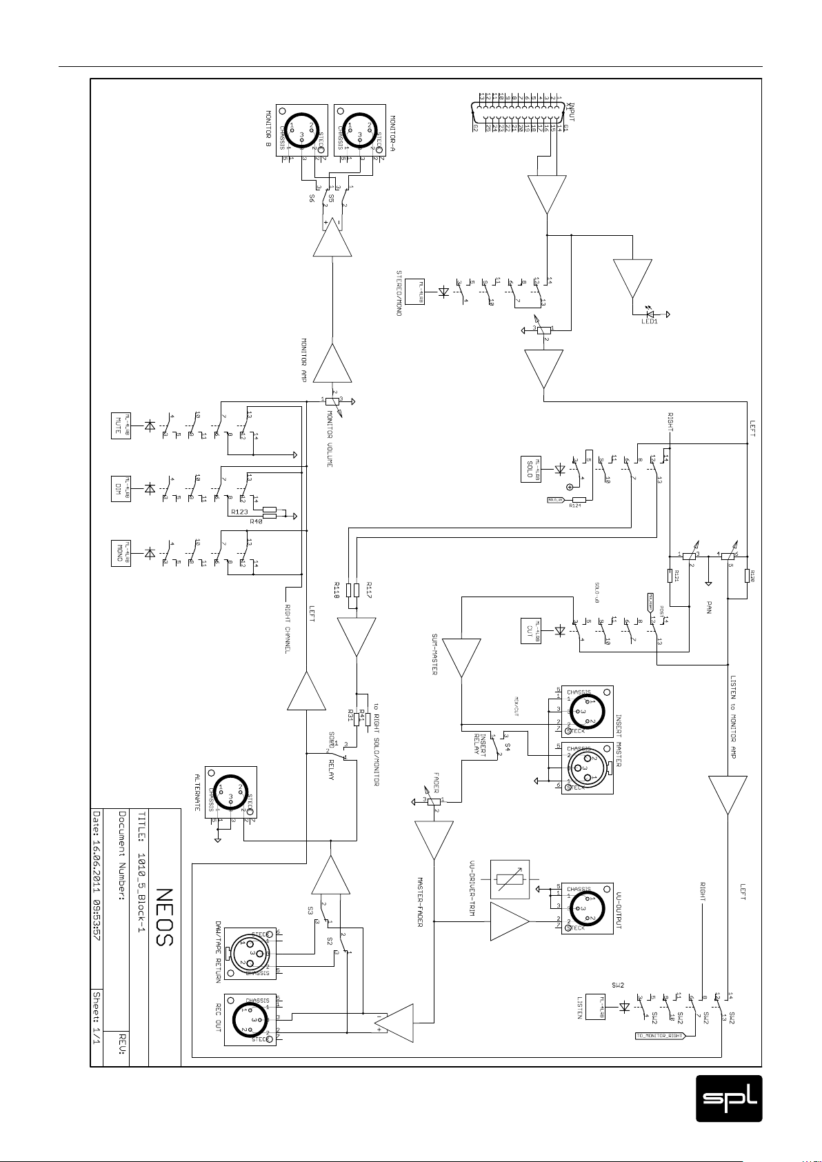
Block Diagram
Neos
23
Page 24

Mounting Dimensions
Dimensions and Weight
Front panel including rack brackets 19 Zoll/7 HE (483 x 310 mm)
Front panel without rack brackets 4 4 0 mm
Housing (W x H x D) 483 x 235 x 330 mm, Depth w, Sockets 355 mm
Fur ther dimensions see diagramm (in millimeters)
Weight 14,1 kg
130
310
62
123
293
24
Neos
Page 25

Zero and ten degree
The Neos comes with 19” rack-mounting side brackets. As you can see here, the holes on the
side of the housing allow for two rack-mounting positions (0 and 10 degrees).
The bracket holes have been designed in order to allow for an easy flush mounting in vertical
or horizontal racks. If it were needed, the brackets can always be adjusted in order to flush
mount the device in the rack. Do consider that all installations, specially without a rack
system, ought to be performed by a specialist and always taking into account the maximum
load capacity.
Mounting Angles
Neos
25
Page 26

Manual Neos
Modell 1010
26
Neos
 Loading...