

Page 1
Manual
N
A
L
C
A
E
B
0
1
1
-
2
2
Mid Side
-
3
3
-
4
4
-
5
5
-
6
-
INSERT MUTE ACTIVE
6
7
7
-
8
8
-
9
9
-
1
0
0
1
-
E
V
L
E
L
5
.
0
0
.
4
6
.
0
3
.
0
2
.
0
1
.
0
1
0
+
/
–
0
1
1
-
2
2
-
0
.
7
0
.
8
0
.
9
3
3
-
4
4
-
5
5
-
6
-
6
7
7
-
8
8
-
9
9
-
1
0
0
1
-
FILTER
LOW
FILTER
RANGE
OFF MUTE
FLOAT
INSERT
OFF
W
O
E
I
D
R
T
E
H
T
6
.
S
0
0
.
8
4
.
0
2
.
0
2
0
P
T
U
U
T
O
0
1
-
3
1
1
-
4
1
-
1
.
5
5
1
-
6
1
-
T
8
-
F
-
5
E
L
-
2
0
2
3
4
dB
T
H
G
I
R
D
I
M
M/S Master
-10dB
PPM M/S
E
D
I
VU
S
Made in Germany
Model
1020
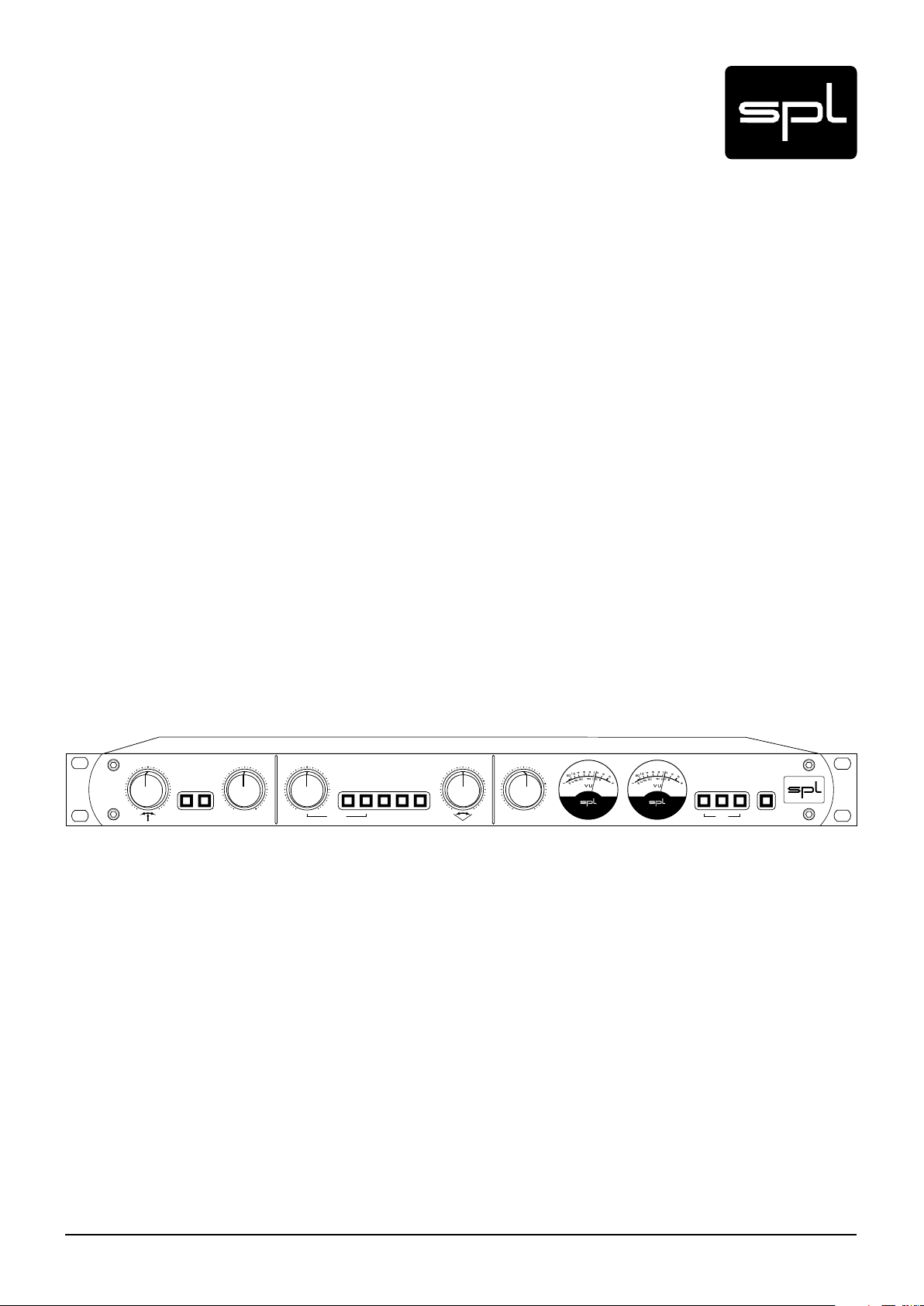
M/S Master
Model 1020
Analog Processor for M/S Mastering
Page 2

Manual M/S Master, Model 1020
Version 1.2 – 1/2012
Developer: Wolfgang Neumann
This manual contains a description of the product. It in no way represents a guarantee of
particular characteristics or results of use. The information in this document has been carefully compiled and verified and, unless otherwise stated or agreed upon, correctly describes
the product at the time of packaging with this document.
Sound Performance Lab (SPL) continuously strives to improve its products and reserves the
right to modify the product described in this manual at any time without prior notice. This
document is the property of SPL and may not be copied or reproduced in any manner, in part
or fully, without prior authorization by SPL.
SPL electronics GmbH
Sohlweg 80, 41372 Niederkruechten, Germany
Phone +49 (0)2163 983 40
Fax +49 (0)2163 983 420
E-Mail: info@spl.info
Internet: spl.info
The construction of the MS Master, Model 1020, is in compliance with the standards and regulations of the European Community.
Notes on Environmental Protection
At the end of its operating life, this product must not be disposed of with regular
household waste but must be returned to a collection point for the recycling of
electrical and electronic equipment. The wheelie bin symbol on the product,
user‘s manual and packaging indicates that. The materials can be re-used in
accordance with their markings. Through re-use, recycling of raw materials, or other forms
of recycling of old products, you are making an important contribution to the protection of
our environment. Your local administrative office can advise you of the responsible waste
disposal point.
WEEE Registration: 973 349 88
© 2012 SPL electronics GmbH. All rights reserved. Names of other companies and their
products are trademarks of their respective owners.
2
M/S Master
Page 3

Symbols and Notes 4
Scope of Delivery 4
Important Security Information 4
Hook Up 5
Introduction 6
M/S Stereophony 6
M/S Mastering, M/S Master, Application examples 7
Rear Panel 8
Signal Connections, Input and Output Electronics, MID INSERT, SIDE INSERT 9
XLR sockets, Balanced connections, Unbalanced connections, Power connection and fuse 10
Voltage Selector, Power switch, GND Lift 11
Operation 11
Overview, ACTIVE 11
Content
Control Elements 12
Input settings, BAL ANCE 12
MID: INSERT, MID: MUTE, LEVEL 13
-/+ FILTER, LOW RANGE, FILTER OFF, FLOAT OFF 14
SIDE: INSERT, SIDE: MUTE, STEREO WIDTH 15
OUTPUT, VU meters, PPM, M/S 16
-10 dB, ACTIVE 17
Working with External Processors 18
Compressor, Equalizer 19
Specifications 20
Copy Master Recall Settings 21
M/S Master
3
Page 4
Symbols and Notes
Scope of Delivery
N THIS MANUAL A LIGHTNING SYMBOL WITHIN A TRIANGLE WARNS YOU ABOUT THE
POTENTIAL FOR DANGEROUS ELECTRICAL SHOCKS – WHICH CAN ALSO OCCUR EVEN AFTER
THE MACHINE HAS BEEN DISCONNECTED FROM A POWER SOURCE.
AN EXCLAMATION MARK (!) WITHIN A TRIANGLE IS INTENDED TO MAKE YOU AWARE OF
IMPORTANT OPERATIONAL ADVICE AND/OR WARNINGS THAT MUST BE FOLLOWED. BE
ESPECIALLY ATTENTIVE TO THE SE AND ALWAYS FOLLOW THE ADVICE THEY GIVE.
The symbol of a lamp directs your attention to explanations of important functions or applications.
Attention: Do not attempt any alterations to this machine without the approval or supervision of SPL electronics GmbH. Doing so could nullify completely any and all of your warranty/
guarantee rights and claims to user support.
The scope of delivery comprises the Frontliner, the external power supply, the guarantee card
and this manual.
Please keep the original packaging. In case of a service procedure the original packaging
ensures a safe transport. It also serves as a safe packaging for your own transports if you do
not use special transportation cases.
Important Security Information
Please note and retain this manual. Carefully read and follow all of the safety and operating
instructions before you use the machine. Be doubly careful to follow all warnings and special
safety instructions noted in this manual and on the unit.
Connections: Only use the connections as described. Other connections can lead to health
risks and equipment damage.
Water and humidity: Do not use this machine anywhere near water (for example near a wash
basin or bath, in a damp cellar, near swimming pools, or the like). In such cases there is an
extremely high risk of fatal electrical shock s!
Insertion of foreign objects or fluids: Never allow a foreign object through any of the machine‘s
chassis openings. You can easily come into contact with dangerous voltage or cause a damaging short circuit. Never allow any fluids to be spilled or sprayed on the machine. Such actions
can lead to dangerous electrical shocks or fire!
Opening the unit: Do not open the machine housing, as there is great risk you will damage the
machine, or – even af ter being disconnected – you may receive a dangerous electrical shock!
Electrical power: Run this machine only from power sources which can provide proper power
in the range from 100 to 250 volts. When in doubt about a source, contact your dealer or a
professional electrician. To be sure you have isolated the machine, do so by disconnecting all
power and signal connections. Be sure that the power supply plug is always accessible. When
not using the machine for a longer period, make sure to unplug it from your wall power socket
and from the guitar amp.
Cord protection: Make sure that your power and guitar amplifier signal cords are arranged
to avoid being stepped on or any kind of crimping and damage related to such event. Do not
allow any equipment or furniture to crimp the cords.
Power connection overloads: Avoid any kind of overload in connections to wall sockets,
extension or splitter power cords, or to signal inputs. Always keep manufacturer warnings
and instructions in mind. Overloads create fire hazards and risk of dangerous shock s! >
4
M/S Master
Page 5

Lightning: Before thunderstorms or other severe weather, disconnect the machine from wall
power (but to avoid life threatening lightning strikes, not during a storm). Similarly, before
any severe weather, disconnect all the power connections of other machines and antenna and
phone/network cables which may be interconnected so that no lightning damage or overload
results from such secondary connections.
Air circulation: Chassis openings offer ventilation and serve to protect the machine from overheating. Never cover or otherwise close off these openings. Never place the machine on a soft
surface (carpet, sofa, etc.). Make sure to provide for a mounting space of 4-5 cm/2 inches to
the sides and top of the unit when mounting the unit in racks or on cabinets.
Controls and switches: Operate the controls and switches only as described in the manual.
Incorrect adjustments outside safe parameters can lead to damage and unnecessary repair
costs. Never use the switches or level controls to effect excessive or extreme changes.
Repairs: Unplug the unit from all power and signal connections and immediately
contact a qualified technician when you think repairs are needed – or when moisture or foreign objects may accidentally have gotten in to the housing, or in cases
when the machine may have fallen and shows any sign of having been damaged.
This also applies to any situation in which the unit has not been subjected to any
of these unusual circumstances but still is not functioning normally or its performance is substantially altered.
In cases of damage to the power supply and cord, first consider turning off the main circuit
breaker before unplugging the power cord.
Important Security Information
Replacement/substitute parts: Be sure that any service technician uses original replacement
parts or those with identical specifications as the originals. Incorrectly substituted parts can
lead to fire, electrical shock, or other dangers, including further equipment damage.
Safety inspection: Be sure always to ask a service technician to conduct a thorough safety
check and ensure that the state of the repaired machine is in all respects up to factory standards.
Cleaning: In cleaning, do not use any solvents, as these can damage the chassis finish. Use
a clean, dry cloth (if necessary, with an acid-free cleaning oil). Disconnect the machine from
your power source before cleaning.
Be very careful to check that the rear chassis power selection switch is set to the correct
local line voltage position before using the unit (230 V position: 220-240 V/50 Hz, 115 V position: 110-120 V/60 Hz)! When in doubt about a source, contact your dealer or a professional
electrician.
Before connecting any equipment make sure that any machine to be connected is turned off.
Follow all safety instructions on pages 4 and 5 and read further information on connections
on pages 7-10.
Place the unit on a level and stable surface. The unit’s enclosure is EMC-safe and effectively
shielded against HF interference. Nonetheless, you should carefully consider where you place
the unit to avoid electrical disturbances. It should be positioned so that you can easily reach
it, but there are other considerations. Try not to place it near heat sources or in direct sunlight,
and avoid exposure to vibrations, dust, heat, cold or moisture. It should also be kept away
from transformers, motors, power amplifiers and digital processors. Always ensure sufficient
air circulation by keeping a distance of 4-5 cm/2 inches to the sides and top of the unit.
Hook Up
M/S Master
5
Page 6

Introduction
M/S Stereophony
Our ability to identify the direction and distance of a sound source is the essence of spatial
hearing. The human ear can identify level and time differences from ear to ear very precisely
and use that information to localize sound. At frequencies up to 1500 Hz the ear analyzes basically time differences to localize sound, while above this frequency it uses level differences.
Our hearing provides excellent conditions to apply room information even to artificially generated sounds. Regardless of the deficiencies and differences that loudspeakers and headphones might present during playback, the human ear needs only the signals to be codified
in, at least, two channels, in order to be able to identify time and level variations, which result
in spatial hearing.
This sort of recording and playback that includes spatial information is known as stereophony
(from Greek stereos = solid or three-dimensional). The resulting stereo image is called panorama. Besides the two-channel stereophony there are several other formats of stereophony.
The common conception of „stereo“ as a two-channel recording is thus incorrect.
Equally incorrect is the concept that the encoding of a stereo signal is always done in a right
and a left channel. This idea is based on the fact that we have a right and a left ear and that
all two-channel recording and playback systems use the same right/left format. It is also not
true that all recordings are made with a microphone for the lef t channel and a microphone for
the right channel.
The differences between the most important microphone techniques have much more to do
with level and time differences. Due to the advantages and disadvantages that each technique provides, more often than not they are combined during production to achieve L/R playback.
While there are several stere o te chnique s that can be applied during mi king, for sign al proces sing during production there is only one technique that is actually useful: M/S. „M“ stands for
Middle (or Mid) and „S“ for Side, which means that signals are separated from the middle
to the sides, instead of from left to right. M/S can be actually applied during recording: two
microphones with different polar patterns record direct and spatial information.
– Besides the microphone technique, M/S can also be used as an alternative stereo encoding
for signal processing, which means that signals do not necessarily need to be recorded with
the M/S microphone technique to be able to apply M/S encoding afterwards (at the mastering
stage, for example).
In fact, M/S encoding can be generated from L/R encoding by summing and subtracting
signals:
M = L + R, S = L – R
The sum of the left and right signals in the Mid signal corresponds to the mono signal of the
L/R encoding. The Side signal is also created from the L/R signal by inverting the polarity of
the rig ht channel. The sum of phase-inverted signals results in the cancellation of mono information in the signals summed; thus, the Side signal is made up of the differences between L
and R. The detailed formula may be clearer: M = L + R, S = L + (-R). The minus sign stands for
the phase inversion.
It is also possible to create a L/R signal encoding from an M/S encoding by summing and
subtracting the sig nals, what is usually called M/S decoding:
L = M + S, R = M - S
Mathematically, the sum and subtraction of signals guarantees a lossless conversion from
L/R to M/S and back to L/R, which is a very important aspect for using M/S encoding for signal
processing.
6
M/S Master
Page 7

M/S encoding is also used for VHF radio transmission. In this case, the Mid signal is sent with
much higher energy. If the reception is not very good, a stereo receiver can switch to mono to
retain the most important information. A mono receiver will always receive a mono compatible signal.
Equally beneficial is M/S encoding when using „Joint Stereo“ compression with MP3. As long
as there is almost no information in the side signal, the compression rate can be higher as
with L/R encoding.
Thus, in audio production M/S encoding is the best way to ensure full mono compatibility.
M/S encoded signals provide an adequate way to control and ensure mono compatibility: the
reduction of the Side signal results in the increase of the mono signal.
M/S Mastering
The use of a mid (M) and a side (S) signal instead of the usual L/R signal results in a much
wiser musical processing.
High-energy Mid signals (vocals, snare, bass guitars, etc.) can be easily separated from Side
signals (guitars, keyboards, cymbals, etc.). When mastering sum signals, M/S encoding is
often the best option to be able to target single elements within a mix.
The M/S Master allows you to directly correct the balance in the mid frequency range and
improve the depth and transparency of stringed instruments. Thanks to the inserts you can
also use filters and effects (compressors, EQs, De-essers) more precisely. Thus, elements
like vocals can be processed without affecting the overall ambience — removing vocal sibilance doesn‘t affect cymbals, for example. On the other hand, the stereo image can also be
enlarged without affecting the mono information. Not to mention the fantastic possibilities to
process ambience that M/S encoding provides.
Introduction
M/S Master
• Analog tool for M/S encoding
• Active control of M/S mix ratio
• Seamless integration of external processors
• One-button insertion of outboard gear in the M/S or L/R path
• Dif ferent VU-meter modes
• Low cut filter for the Side signal
• FLOAT function for better mono compatibilit y
Application examples
• Stereo image enhancement after mixdown or during mastering
• Reverb and ambience reduction without losing brilliance
• Independent processing of rhythmic elements, pads and other sounds placed off the
center of the stereo image without af fecting central elements, and viceversa.
• Precise EQ processing of elements that sound too dull
• Specif ic dynamic correction of lively par ts
• Dynamic reduction in Side elements without af fecting drum transients
M/S Master
7
Page 8

Rear Panel
Wiring Diagram
LEFT RIGHTINPUT
RIGHT LEFTINPUT
DAW/Converter
Console, Patchbay,
1=GND, 2=hot (+), 3=cold (-)
RETURN SENDMID INS.
SEND RETURNMID INS.
Pin 3 = (–) cold
Pin 3 to GND (Pin 1)
Pin 2 = (+) hot
operation connect
Pin 1 = GND
For unbalanced
RETURN SENDSIDE INS.
External Processors
(Compressor, DeEsser ...)
Pin wiring XLR output sockets:
21
3
External Processors
(Equalizer, Reverb ...)
LEFT RIGHTOUTPUT
SERIAL No.
CAUTION
RISK OF ELECTRIC SHOCK
VOLTAGE | FUSE
SEND RETURNSIDE INS.
RIGHT LEFTOUTPUT
DAW/Converter
Console, Patchbay,
www.spl.info
MADE IN GERMANY
DO NOT OPEN
AVIS: RISQUE DE CHOC ÉLECTRIQUE – NE PA S OUVRIR
230V ~50Hz
I
GND LIFT
GND
GND LIFT
315mA slow
630mA slow
115V ~60Hz
0
Make sure that
reflects the correct
local power line voltage.
the voltage switch setting
Pin wiring XLR input sockets:
1=GND, 2=hot (+), 3=cold (-)
1
3
PUSH
2
8
M/S Master
Page 9

Connections
Signal Connections
Turn off the unit before connecting or disconnecting any cable or equipment to it. Otherwise
you risk the possibility of damaging your ears or equipment.
Input and Output Electronics
The input and output electronics of the M/S Master possesses two very distinctive features:
1. Bridge circuits that keep the signal flow constant, regardless of malfunctioning equipment and power outages (power fail safety by relay hard bypasses).
2. External processors connected to the INSERTs can be used for A/B stereo processing
without the need of any recabling.
The bridge and insert circuits rely on high-quality relays. Contact surfaces are gold-plated to
provide better conductivity and encapsulated to avoid external influences due to climate or
atmospheric conditions.
Power fail safety is only provided under two conditions:
1. If the M/S Master is operated in single mode without processors at its inserts, the insert
send/return sockets have to be bridged with XLR patch cables.
2. If the M/S Master is operated together with inserted processors, the inserted processors
must have relay hard bypasses, too. Otherwise these machines can break off the signal
flow (also refer to the next chapter „MID INSERT, SIDE INSERT“).
Rear Panel
MID INSERT, SIDE INSERT
Both MID and SIDE channels have insert points that enable you to integrate external processors in each channel‘s path. The INSERT SEND outputs the signal to the external processor;
the processed signal is then input back through the INSERT RETURN.
IMPORTANT: If there are no processors closing the loop, the inserts have to be bridged with
XLR patch cables. Use the shortest cables possible.
You can make a loop with one or more processors and you can even use a patchbay if needed.
IMPORTANT: Cabling does not need to be changed in order to use processors connected to
the M/S Master for L/R stereo processing.
Simply disengage the ACTIVE push button on the front panel or turn off the M/S Master to
use the processors as you usually would. Thus, the stereo signal is not M/S encoded but
forwarded directly to the connected processors.
NOTE: The VU-meters drop considerably when you disengage the ACTIVE push button while
the MID INSERT and SIDE INSERT push buttons are engaged. If the INSERT push buttons are
not engaged, the VU-meter remains active. This applies to all VU-meter modes and is based
on the complex relay circuits of the inputs, outputs, insert points, and L/R and M/S encoding.
Considering that the push button setting described does not correspond to an actual work
function, it can be neglected.
M/S Master
9
Page 10

Rear Panel
Connections
XLR sockets
All signal connections are made via balanced XLR connectors. Inputs are always female and
accept male connectors; outputs are always male. All in all, a very comprehensible principle.
Balanced connections
It is impossible to exclude interferences when a single audio signal is transmitted. Shielding
is effective against electric, but not against electromagnetic influences. Motors, transformers, and alternating current can always induce interferences. But even if the transmission
would succeed, differences in ground potentials between driver and receiver would produce
disturbances.
In balanced connections a reference signal with reversed polarity is transmitted additionally
to the audio signal through a second wire. The ground signal is routed separately through
a third wire. Input and output stages are drivers and receivers, and the receiving stage can
suppress interferences by subtracting the difference between audio and reference signal.
Unbalanced connections
Unbalanced connections from and to RCA or 1/4“ TS sockets can be made without adaptors to
the balanced XLR sockets. The correct wiring is important. The diagram shows the pin configuration of the XLR sockets and how to correctly connect them for unbalanced connections:
Input
balanced
2
1
3
unbalanced
2
1
3
balanced
1
2
3
Output
unbalanced
1
2
3
1=GND
2=hot (+)
3=cold (-)
Connections to RCA sockets are always unbalanced, a wiring to jack connectors can be both
balanced (1/4“ TRS/stereo jack) or unbalanced (1/4“ TS/mono jack). We recommend to use
individually configured cables from XLR to RCA or jack sockets instead of adaptors. You can
get cables in any needed configuration from audio dealers. With the diagram above, the
dealer can ensure to provide the appropriate cable for your application.
Power connection and fuse
I
0
Connect the power cord to the rear MAINS INPUT socket. Transformer, power cord and case
connection conform to VDE, UL and CSA requirements.
The fuse is accessible from outside and placed right behind the flap right from the socket.
Fuse ratings are 315 mA slow blow (
230
volts) or 630 mA slow blow (
115
volts).
I
0
10
M/S Master
Page 11

Switches
Rear Panel
Voltage Selector
The rear panel VOLTAGE selector sets the local line voltage (115 V position: 110-120 volts/6o Hz,
230 V position: 220-240 volts/50 Hz). The diagram shows the correct switch position for 230 V
power supply.
BEFORE you connect electrical power make sure that the VOLTAGE selector setting reflects
the correct local power line voltage.
Power switch
Use the POWER switch on the rear panel to turn the unit on or off. The VU-meters on the front
panel will light on as soon as you turn the unit on, regardless of the position of the ACTIVE
push button. Thus, they fulfill a second function as power indicators.
GND Lift
The rear panel GND LIFT switch eliminates hum by separating the internal ground from the
unit’s housing ground. Hum can, for example, result when this unit’s housing has a common
ground connection with other devices that might have a different ground potential. The switch
is usually deactivated to retain the shielding of the housing.
VOLTAGE | FUSE
230V ~50Hz
315mA slow
115V ~60Hz
630mA slow
GND LIFT
GND LIFT
GND
I
0
Overview
N
A
L
C
A
E
B
0
1
1
-
2
2
Mid Side
-
3
3
-
4
4
-
5
5
-
6
-
7
INSERT MUTE ACTIVE
6
7
-
8
8
-
9
9
-
1
0
0
1
-
E
V
L
E
L
5
.
0
0
.
4
6
.
0
3
.
0
2
.
0
1
.
0
1
0
+
/
–
0
1
1
-
2
2
-
0
.
7
0
.
8
0
.
9
3
3
-
4
4
-
5
5
-
6
-
7
6
7
-
8
8
-
9
9
-
1
0
0
1
-
FILTER
LOW
FILTER
RANGE
OFF MUTE
FLOAT
INSERT
OFF
W
O
E
I
D
R
T
E
H
T
6
.
S
0
0
.
8
4
.
0
2
.
0
2
0
P
T
U
U
T
O
0
1
-
3
1
1
-
4
1
-
1
.
5
5
1
-
6
1
-
T
8
-
F
-
5
E
L
-
2
0
2
3
4
dB
Overview
The control elements on the front panel of the M/S Master are divided into three sections:
MID, SIDE and OUTPUT/VU-meters.
1. In the MID section you adjust the balance of Mid signals in the stereo panorama and their
level.
2. In the SIDE section you define the stereo width and apply filters as well as other functions to the signal.
3. In the OUTPUT/VU section you adjust the output level, monitor the VU-meters and switch
on, with the ACTIVE push button, the M/S Master, as well as engage the insert paths
ACTIVE
Use the ACTIVE push button to switch on or off the totality of the electronic components of the
M/S Master. When switched off, input signals are forwarded directly to the outputs.
Operation
T
H
G
I
R
D
I
M
M/S Master
PPM M/S
E
D
I
S
ACTIVE
-10dB
Made in Germany
Model
1020
VU
The ACTIVE push button accomplishes two very important tasks:
1. A/B comparison between processed and unprocessed audio material.
2. Switching between M/S and A/B stereo processing, including external processing
without the need of any recabling.
Refer to the information on „Input and Output Electronics“ and „MID INSERT, SIDE INSERT“
on page 9.
M/S Master
11
Page 12

Operation
Input settings
Input settings
Given that all productions are mixed differently, it is impossible to provide general recommendations regarding settings. By default, settings correspond to a passive M/S encoder without
applying any processing, i.e. L/R stereo is encoded as M/S stereo and the rest of the M/S
Master functions have no influence on the sound. This is the best starting point to get to know
the functions and settings of the unit:
MID/BALANCE: 0 (center position)
MID/INSERT and MUTE: OFF
SIDE/FILTER: 0 (center position)
SIDE/all switches: OFF
SIDE/STEREO WIDTH: 1 (around three o‘clock)
OUTPUT: 0 (around three o‘clock)
VU-switch: all OFF
ACTIVE: ON
At this point, when you switch on or off the M/S Master processing there is no real difference
in the sound. And this is where the fun begins: the original L/R signal is now M/S encoded and
can be processed with the integrated as well as with external processors.
Control Elements
N
A
L
C
A
E
B
0
1
1
-
2
2
-
3
-
4
-
5
-
6
-
7
-
8
-
9
-
0
3
4
8
9
1
0
1
-
Do note that the M/S Master features exclusively high-quality potentiometers (ALPS RK 27 or
„Big Blue“). But even these potentiometers can exhibit minor imprecisions. Therefore scale
values can be subject to minor deviations. For a perfect 1:1 comparison with the aforementioned values you ought to consider minor tolerances and compensate if needed. The M/S
Master was not conceived to provide a perfect comparison between L/R and M/S encoding.
Its primary goal is individual processing of audio material, therefore, minor deviations in scale
values do not have a considerable impact on the overall performance. If you wish to have
a higher technical precision, you can always use specifically designed measurement equipment (phase correlation meters, etc.). We have taken these factors in consideration during
development in order to keep a reasonable price/performance ratio.
MID section
BALANCE
5
6
7
Use the BALANCE control to place the Mid signal in the stereo panorama. With this control,
the Mid signal created from the sum of L and R can be placed anywhere along the stereo
panorama. In practice, hard left and hard right are not commonly used: normal settings are
somewhere around +/- 1, and up to 3 at the most. Maximal values are meant to serve as a reference for testing loudspeakers and acoustical conditions in order to hear if both sides sound
uniformly.
The M/S Master provides two measuring instruments to check Mid balance:
12
1. The VU-meters. If one channel is continuously higher while in L/R display mode, some
adjustment might be needed.
2. A phase correlation meter (or omnimeter). Adjust the BALANCE control in order for the
phase correlation meter to show a perfectly balanced central position..
M/S Master
Page 13

MID section
Control Elements
MID: INSERT
Use the INSERT switch to activate the insert point for the Mid channel. You can connect any
mono processor, or a single channel of a stereo unit, to the insert jacks on the rear panel.
As soon as you engage the INSERT switch, the connected units are integrated into the M/S
Master processing path. To use the processors independently of the M/S Master, as well as
for mono or L/R processing, disengage the ACTIVE switch of the M/S Master.
Refer to the information on „Input and Output Electronics“ and „MID INSERT, SIDE INSERT“ on
page 9 and „AC TIVE“ on page 11.
For more information on how to use external processors go to „Working with External
Processors“ on page 18.
MID: MUTE
The MUTE push button silences the Mid signal. There is another MUTE button for the SIDE
section. When you isolate either channel from the other, you can actually concentrate better
and gain a more focused perspective on the audio material of that particular channel. The
relation between the mixed elements is easier to distinguish and, at the same time, overprocessing becomes much more evident. Focused processing is also made easier and the control
over previous work becomes very revealing.
LEVEL
Use the LEVEL control to set the Mid signal volume in relation to the Side signal. The start
position is set hard right. The more you turn the control to the left, the more the volume decreases. When turned fully lef t, the Mid signal disappears completely.
Together with the STEREO WIDTH control in the SIDE section, the LEVEL control determines
the ratio between both channels. Understanding the interdependence of these controls is
essential when working with them. Thus, you should always ponder if it is more appropriate
to decrease one or increase the other. For example: to expand the stereo image without losing
mono compatibility, the most convenient would be to increase the STEREO WIDTH to positive
values. On the contrary, if you were to decrease the LEVEL of the (Mono) Mid signal without
changing the STEREO WIDTH value, mono compatibility would also be af fected. Typical application examples include the need to emphasize or attenuate elements in the Mid signal, with
the intention of modifying the depth of elements (like the vocals) placed at the front or back of
a mix, or even to alter the relation between Mid and Side elements.
Mid
INSERT MUTE
Mid
INSERT MUTE
V
E
L
5
.
0
4
.
0
3
.
0
2
.
0
1
.
0
0
E
L
0
.
6
0
.
7
0
.
8
0
.
9
1
In this last case, and as described above, the LE VEL and STEREO WIDTH controls provide optimal
conditions to make delicate adjustments. When it comes to localization, as in the first case, it is
interesting to know that the depth of a signal is strongly influenced by high-frequency, monophonic differences, which are then shaped by the ear. Sounds above 1.5 kHz coming from in front
of the receiver are more intensely reflected by the ear and are responsible for a good directivity.
Given this, processing the relevant frequency range in the Mid signal with an EQ connected to the
MID INSERT can help modify positioning. Signal presence is intensif ied by emphasizing frequencies bet ween 1.5 kHz and 2 kHz, which results in a small increase in the overall level.
Dynamic differences throughout the audio material are one of the most common situations
that require correcting. For example, the level of vocals usually changes when the song goes
from the verse to a chorus, so it might be necessary to control the dynamics. The high quality
of the potentiometers is evident on their perfectly adjusted torque – dynamic adjustments
are thus much more carefully controlled.
M/S Master
13
Page 14

Control Elements
–
/
+
0
1
1
-
2
-
3
-
4
-
5
-
6
-
7
-
8
-
9
-
2
3
4
5
6
7
8
9
1
0
0
1
-
FILT ER
SIDE section
-/+ FILTER
The „-/+“ knob controls the only actual effect on the M/S Master: a shelving filter meant to
boost or attenuate low and mid frequencies in the Side signal. The frequency range below
the given cut-off frequency is equally boosted. Use the LOW RANGE push button next to it
to set one of two possible cut-off frequencies, in order to define the frequency range to be
processed (see the next section).
Low and mid frequencies up to 2 kHz are very important when it comes to signal positioning,
that is why the filter is set to affect this specific frequency range. As mentioned before, for
frequencies up to 1.5 kHz it is time differences that define localization. Like any other filter,
the „+/-“ filter affects signal phase, which results in time shifts. An increase in intensity
results in an increase of the influence on the perception of the stereo image according to the
scale (attenuation to the left, boosting to the right).
Thus, filtering of low and mid frequencies increases the correction and shaping possibilities
with the on-board elements of the M/S Master. At the same time, the integration of an EQ in
the Side insert broadens even more the possibilities to make selective frequency processing.
The „+/-“ control is therefore a good complement to the STEREO WIDTH setting; the combination of both provides a wide and effective variety of processing approaches.
Side
LOW
RANGE
FLO AT
FILTER
OFF MUTE
Side
LOW
RANGE
FLO AT
FILTER
OFF MUTE
Side
LOW
RANGE
FLO AT
FILTER
OFF MUTE
OFF
OFF
OFF
INSERT
INSERT
INSERT
LOW RANGE
Use the LOW RANGE push button to set the cut-off frequency of the „+/-“ filter. When
engaged, the cut-off frequency is set to 800 Hz so you can process the low frequency range.
When disengaged, the cut-off frequency is set to 2.2 kHz, which means that the „+/-“ filter
processes all frequencies below 2.2 kHz.
FILTER OFF
Use this push button to disengage the „+/-“ filter. By disengaging the filter, the processing is
done solely on the Side signal encoded directly from the original L/R signal. Thus, the actual
L/R stereo image, ambience, etc. can be accurately appraised and processed if needed.
FLOAT OFF
FLOAT refers to a signal created from L/R that is mixed with the Side signal. Actually, in
addition to the L/R signal, from where the M/S encoding is created, a part of the L/R signal
(reduced in level) is attached to the Side signal. This is done as a parallel process, i.e. it is not
added to the encoded signal. This portion accounts for 10% at the most.
Mixing the FLOAT signal with the Side signal has two major advantages:
1. It avoids the risk of having a negative phase correlation ratio.
2. The less substance the Side signal has, the easier and safer the processing is with the
FLOAT signal.
In relation to 1: Even extremely wide stereo images remain mono compatible. In this case,
FLOAT extends the bandwidth, so a compromise between mono compatibility and stereo
image is easier to reach.
In relation to 2: If the original Side signal is made up of ambience or pad sounds, processing
can be very difficult. The risk of extreme settings is quite high because it is very hard to identify sonic differences clearly. Thus, the FLOAT signal provides a good sonic reference – even
if only during processing. After all, the FLOAT signal can be turned off anytime (once you are
done optimizing settings, for example).
Engage the FLOAT OFF push button to listen only to the Side signal created from the M/S encoding.
14
M/S Master
Page 15

SIDE section
Control Elements
SIDE: INSERT
Use the INSERT switch to activate the insert point for the Side channel. You can connect any
mono processor, or a single channel of a stereo unit, to the insert jacks on the rear panel.
As soon as you engage the INSERT switch, the connected units are integrated into the M/S
Master processing path. To use the processors independently of the M/S Master, as well as
for mono or L/R processing, disengage the ACTIVE switch of the M/S Master.
Refer to the information on „Input and Output Electronics“ and „MID INSERT, SIDE INSERT“ on
page 9 and „AC TIVE“ on page 11.
For more information on how to use external processors go to „Working with External
Processors“ on page 18.
SIDE: MUTE
The MUTE push button mutes the Side signal. There is another MUTE button for the MID
section. When you isolate either channel from the other, you can actually concentrate better
and gain a more focused perspective on the audio material of that particular channel. The
relation between the mixed elements is easier to distinguish and, at the same time, overprocessing becomes much more evident. Focused processing is also made easier and the control
over previous work becomes very revealing.
STEREO WIDTH
Use the STEREO WIDTH control to adjust the Side signal level in relation to the Mid signal.
When set to 1 (around two o‘clock) there is no difference, i.e. the signal is played back 1:1.
As you turn the control to the right, the Side signal is made bigger. When set hard right (2)
the stereo image is 200% wider. As you turn the control to the left, the Side signal is made
smaller. When set hard left, the Side signal is muted.
Side
LOW
FILTER
RANGE
OFF MUTE
Side
LOW
FILTER
RANGE
OFF MUTE
W
O
E
I
D
R
T
E
T
S
4
.
0
2
.
0
0
H
6
.
0
0
.
8
2
FLO AT
OFF
FLO AT
OFF
1
.
5
1
INSERT
INSERT
Adjustment of the STEREO WIDTH should always be made taking into account the settings
of the „+/-“ filter and the LEVEL control in the MID section. Understanding the interdependence of these controls is essential when working with them. Thus, you should always ponder
if it is more appropriate to decrease one or increase the other. For example: to expand the
stereo image without losing mono compatibility, the most convenient would be to increase
the STEREO WIDTH to positive values. On the contrary, if you were to decrease the LEVEL of
the (Mono) Mid signal without changing the STEREO WIDTH value, mono compatibility would
also be affected.
The interaction with the „+/-“ filter is quite simple and it could almost be described as a
coarse/fine adjustment: if you have already set the stereo image, you can use the „+/-“ filter
to focus on the details. Please refer to „+/- FILTER“ on page XXX for more important information.
Typical applications where the use of STEREO WIDTH comes in handy are recordings with too
little room ambience (in studios, for example) or too much room ambience (in places with a
reverb time of more than five seconds, like churches). M/S encoding is rather useful to solve
problems that are very difficult or even impossible to work through in L/R format: speech
transmission during events can be easily isolated to improve intelligibility, regardless of the
unfavorable acoustics of a room, hall or stadium.
M/S Master
15
Page 16

Control Elements
P
T
U
U
T
O
8
-
-
0
1
-
3
1
-
4
1
-
5
1
-
5
-
2
6
4
1
-
dB
Output & VU section
OUTPUT
0
2
3
Use the OUTPUT control to attenuate the output signal up to -16 dB or boost it up to +4 dB,
in order to match it to the following unit in the chain. The output level on the VU-meter is
indicated in PPM mode. Before starting any processing, always set the OUTPUT control to 0
(around three o‘clock). That way you can read the Mid and Side signal levels on the VU-meter
without the output setting having any influence on them.
T
F
E
L
T
H
G
I
R
VU meters
The VU meters ( VU = Volume Unit) measure the output level, which ranges from -20 dB to
+5 dB. The meters show the changes in level caused by processing the signal with the M/S
D
I
M
E
D
I
S
Master. The VU meters have two different operating modes: L/R or M/S. That way you can
always have an accurate level reading while working with the M/S Master – including the
changes in level that may be caused by exter nal processors. You may find more detailed information under the descriptions of the „PPM“, „M/S“ and „-10 dB“ push buttons.
PPM M/S
-10 dB
PPM
Use the VU/PPM push button to toggle between VU and PPM display mode. VU mode shows
average level readings and therefore provides information on the overall loudness or energy
VU
of the signal.
PPM mode (PPM = Peak Program Meter) indicates peak levels, similar to AD converter meters,
where it is important to control peak levels in order to avoid the converter from saturating and
distorting. Sometimes it can be useful to activate the -10 dB push button while in PPM mode
to extend the display range.
PPM M/S
-10 dB
M/S
Use the M/S push button to toggle between L/R output level display (M/S push button disengaged) and M/S level display (M/S push button engaged).
VU
The VU-meters are labeled „LEFT“ and „RIGHT“ respectively (left, above the meters). When in
M/S mode, the labels that apply are „MID“ and „SIDE“ (right, below the meters).
In L/R mode the level shown is post output control, which means that it takes into account all
processing that you have made with the M/S Master, including the OUTPUT control.
In M/S mode it shows the output signals of the Mid and Side channels respectively. That way
you can see how processing, including external processors, affects level relations in M/S
encoding. Level changes produced by the OUTPUT control are not shown in M/S mode. To
keep track of the L/R output level switch to L/R mode (M/S push button disengaged).
16
M/S Master
Page 17

Output & VU section
Control Elements
-10 dB
Use this push button to reduce 10 dB the sensitivity of the VU-meters. When the VU-meters‘
needle points at 0 db, it actually corresponds to -10 dBu and the maximum value is +15 dB.
The sensitivity switch allows you to analyze very high level signals that would otherwise be
beyond the range of a normal meter.
ACTIVE
Use the ACTIVE push button to switch on or off the processing electronics of the M/S Master.
When switched off, input signals are forwarded directly to the outputs.
The ACTIVE push button accomplishes two very important tasks:
1. A/B comparison between processed and unprocessed audio material.
2. Switching between M/S and A/B stereo processing, including external processing
without the need of any recabling.
Refer to the information on „Input and Output Electronics“ and „MID INSERT, SIDE INSERT“
on page 9.
PPM M/S
ACTIVE
-10 dB
VU
M/S Master
17
Page 18

Working with External Processors
We will describe in detail the two most common types of processing units used: compressors
(to process dynamics) and equalizers (to correct or shape signals based on frequency).
You can obviously connect all sorts of processors to the inserts of the M/S Master: reverb and
delay effects, a De-esser in the MID INSERT to reduce vocal sibilance, tube processors to add
character to the sound... Whatever suits your needs.
Compressor
Compressors are usually used at the mastering stage to increase level across the entire
frequency spectrum. Loud level peaks are attenuated and the dynamic range of the mix as
a whole is reduced. Afterwards, the signal‘s average level is increased to the original value.
This conventional use of a compressor might or might not work, it depends. Over the last
two decades, dynamic range reduction has steadily increased; almost at the same pace as
sonic quality has decreased – insofar as musically oriented dynamic relationships are used
as benchmark. When optimizing dynamic structures, M/S encoding offers significant advantages over the across-the-board approach of sum compression in L/R format. M/S encoding
allows you to focus on single elements of finished mixes, making it easier to increase overall
loudness while preserving the dynamic range.
Let‘s take, for example, a pop song that sounds fairly balanced, even though the vocals are a
bit too high within the mix. With a compressor in the MID INSERT, you can reduce the level of
the vocals as one of the main elements in the Mid signal. Backing vocals and harmonic instruments, as well as all other elements of the Side signal, are left untouched.
Compressor
The compressor‘s „Auto Gain“ or similar functions should be avoided. Make-up gain shouldn‘t
be necessary either. Otherwise, the (mono) Mid signal could become too loud and other
central instruments like bass drum, snare, bass guitar, etc. could result too imposing. Unless,
of course, the Mid signal needs a push to come through in the mix due to a very dominant Side
signal. When it comes to depth (front/back positioning), there are some EQ techniques that
are very useful and do not affect the overall level too much. Read the section „Equalizer“.
You can always compress a loud Side signal if there are certain instruments that stand out too
much in that channel. The mix will sound more balanced and compact without affecting the
dynamic range and transient structure of the snare and bass drum.
Heavy compression on the Side signal can be also useful to enhance the room ambience of a
mix.
18
M/S Master
Page 19

Equalizer
Working with External Processors
Equalizer
The possibilities that an equalizer provides when working with the Mid or Side signals correspond to the normal applications of an EQ, the full scope of which is beyond our purpose.
Two of the most common functions of an EQ ought to be more than enough to illustrate
the potential of using it as an INSERT: attenuation of low frequencies and boosting of high
frequencies.
Among the most common problems of a mix are booming synth pads and guitar walls with a
very deep frequency response. They can make a Side signal too dense or clash with important
low frequency signals – like bass guitar and bass drum – usually found in the Mid signal. With
an EQ in the MID and/or SIDE INSERT you can focus on that specific frequency range in order
to avoid conflicts. The Mid signal is thus cleansed and the primal elements become more
precise and distinguishable. Selective EQ can give the Side signal more air, making cymbals
and harmonic instruments sound more present without adding too much sharpness to vocals.
Increasing high frequencies in the Side signal usually results in a wider stereo image with a
solid center image.
Another interesting possibility is the processing of individual elements of a mix to affect positioning. The depth of a signal is strongly influenced by high-frequency, monophonic differences, which are then shaped by the ear. Sounds above 1.5 kHz coming from in front of the
receiver are more intensely reflected by the ear and are responsible for a good directivity. In
this situation, an EQ can be used to process the frequency range in question (generally speaking, this will affect Mid signals so you will have to use the MID INSERT). Signal presence is
intensified by emphasizing frequencies between 1.5 kHz and 2 kHz, which results in a small
increase in the overall level.
M/S Master
19
Page 20

Specifications
Inputs & Outputs
Electronically balanced instrumentation amplifiers
Sockets: XLR
Input impedance: 20 kOhm balanced/10 kOhm unbalanced
Output impedance: 150 Ohm balanced/75 Ohm unbalanced
Max. input level: 20 dBu
Max. output level: 20 dBu
Measurements
Frequency response (-3 dB): 10 Hz - 100 kHz
Common mode rejection ratio: › 60 dB
(@ 1 kHz, 0 dBu input level and unity gain)
Total harmonic distortion & noise: 0,007 %
(@ 1 kHz, 0 dBu input level and unity gain)
Signal to noise ratio (A-weighted): -82 dB
Dynamik range (unweighted): 102 dB
Power supply
Toroidal transformer
Fuses: 230 V AC, 50 Hz: 315 mA; 120 V AC, 60 Hz: 630 mA
Voltage selector: 115V/230V
Power consumption: @ 230 V: 9,1 W/10,8 VA ; @ 115 V: 5,6 W/7,1 VA
Dimensions and Weight
Housing (W x H x D): 482 x 88 x 320 mm
(depth including controls and sockets)
Weight: 3,6 kg/7,94 lbs
Notes: 0 dBu = 0,775 V. Specifications subject to change without notice.
20
M/S Master
Page 21

Title:
Album/Gig:
Artist:
Copy Master Recall Settings
6
-
-
5
7
-
-
4
8
-
9
-
0
1
-
0
1
9
0
1
9
-
0
1
-
0
1
9
FILT ER
-
3
-
2
B
-
A
1
L
A
0
N
C
1
E
2
3
4
8
5
7
6
INSERT MUTE ACTIVE
Mid Side
2
.
0
0
.
1
3
.
0
0
.
4
L
E
0
V
.
5
E
L
0
.
6
0
9
.
.
7
0
0
.
8
6
-
-
5
7
-
-
4
8
-
-
3
-
2
-
1
–
/
0
+
1
2
3
4
8
5
7
6
RANGE
LOW
FILTER
OFF MUTE
FLOAT
OFF
INSERT
2
.
0
0
.
4
0
2
6
1
-
dB
4
M
I
D
S
I
D
E
S
T
E
R
0
.
6
E
O
W
I
D
0
T
.
8
H
1
5
.
1
4
1
-
-
1
5
3
1
-
-
1
0
O
U
T
-
8
P
U
T
-
5
-
2
3
0
2
L
E
F
T
R
I
G
H
T
M/S Master
PPM M/S
Date:
Track(s)/Groups:
Engineer:
VU
-10dB
Made in Germany
Model
1020
Page 22

Manual M/S Master, Model 1020
 Loading...