

Page 1
Manual
HPm
Headphone Monitoring Amp in a Dual Slot 500 Series Rack Module
Content
Page 2

Note:
Click on a section or page number to immediately jump to that location.
Content
Content 2
Version 1.0 – 09/2016 3
Scope of Delivery 4
Measurement & Weight 4
Introduction 5
Welcome 5
Specifications 6
General 6
Input 6
Output 6
Installation 7
Installation into a 500 series rack 7
Control Elements 8
Phonitor Matrix 17
Basics of stereo listening 17
Stereo listening with an “traditional“ headphone preamplifier 18
How does the Phonitor Matrix work? 19
Setting of Crossfeed and Speaker Angle 20
Symbols 21
Security Advices 22
Declaration of CE Conformity 27
Notes on Environmental Protection 28
Contact 29
Phase Inversion Ø 9
Crossfeed 10
Speaker Angle 11
Volume 12
Stereo/Mono/Mute 13
Matrix On/Off 14
Center Level 15
Headphone Jacks 16
HPm
Content
Page 3

Version 1.0 – 09/2016
Developer: Bastian Neu
This manual contains a description of the product. In no way it represents a guarantee
of particular characteristics or results of use.
The information in this document has been carefully compiled and verified and, unless
otherwise stated or agreed upon, correctly describes the product. Sound Performance
Lab (SPL) continuously strives to improve its products and reserves the right to modify
the product described in this manual at any time without prior notice.
This document is the property of SPL and may not be copied or reproduced in any manner, in part or fully, without prior authorization by SPL.
HPm
Content
3
Page 4

Scope of Delivery
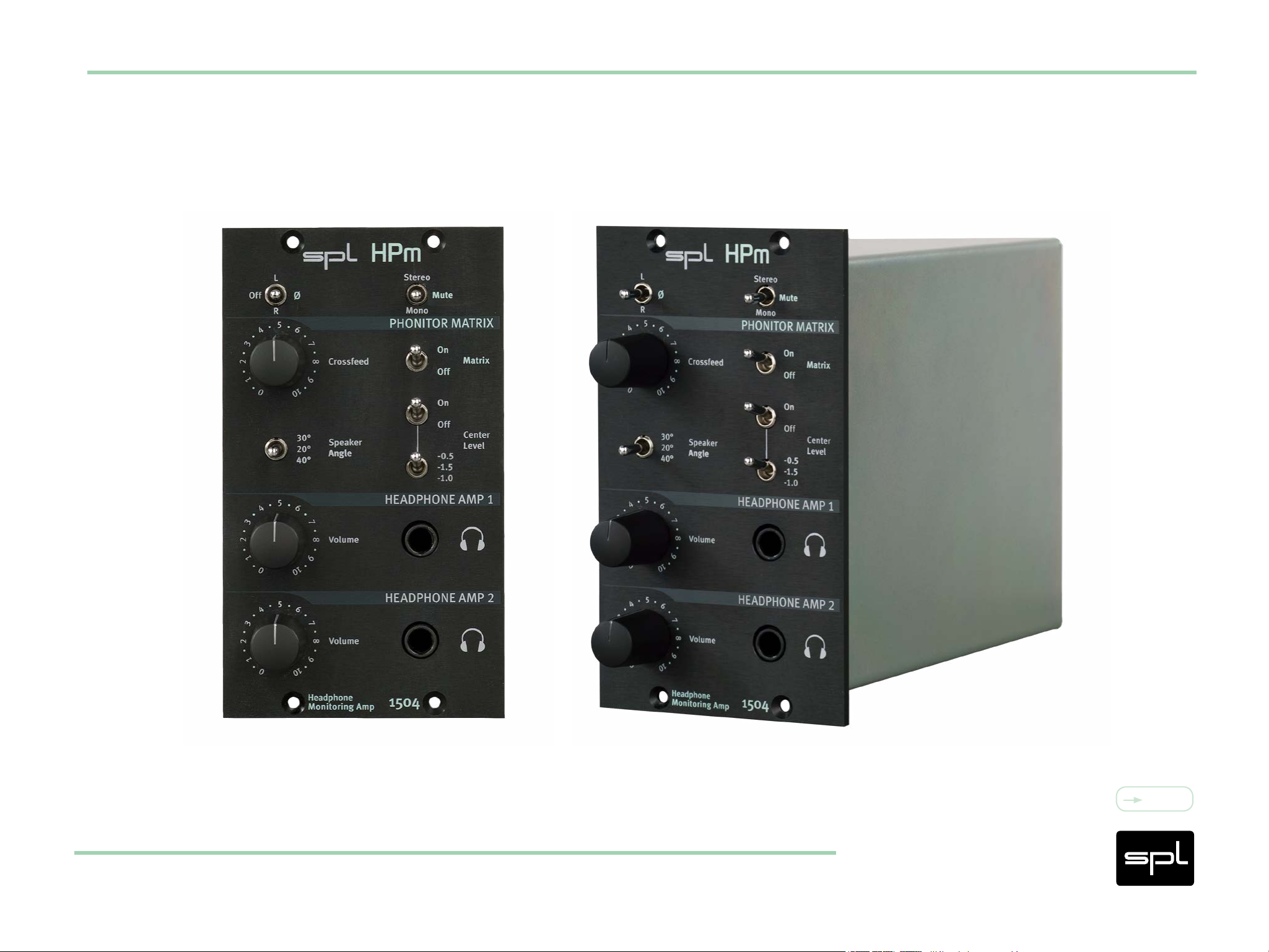
HPm – 500 Series Rack Module
Quickstart/Product Overview
Measurement & Weight
Dual Slot 500 Series Rack Module
Weight: 1.76 lbs (0.8 kg)
Please keep the original packaging. In a service case the original packaging ensures a safe transport.
HPm
Content
4
Page 5

Welcome
and thank you for purchasing the Headphone Monitoring Amp HPm. With the HPm the
Phonitor Matrix is making headway into the world of 500 series rack modules.
Each of the two headphone outputs is fed with a separate amplifier to allow independent
operation of two headphones with high-quality amplification.
With the Phonitor Matrix you control Crossfeed, Speaker Angle and Center Level to create
speaker-like listenig and monitoring on headphones.
Introduction
The HPm can easily be inserted between the DAW and a monitor controller because the
input signals of the HPm are slaved through to the outputs of the 500 series rack.
Phase Inversion of left or right channel as well as a Stereo/Mono/Mute switch round off
the feature set of the HPm.
Content
HPm
5
Page 6

General
Frequency Response: 10 Hz - › 100 kHz
Noise: -92.3 dBu (A-weighted)
Total Harmonic Distortion: 0,0024% (0 dBu output level//600 Ohm)
Current consumption: 260 mA at +/- 16 Volt DC
Input
Specifications
Electronically balanced
Impedance: approx. 10 kOhm
Max. Input Level: +21 dBu
Output
Max. Output Level:
+18 dBu @ 600 Ohm
+15 dBu @ 300 Ohm
Content
HPm
6
Page 7

Installation into a 500 series rack
• Please read the manual that comes with the 500 series rack. You should gain all
information necessary for the installation process.
• Your 500 series rack should be switched off and the power cable should not be
connected.
• Insert the HPm module into two adjacent free slots of your rack. Make sure the connectors of the HPm is precisely aligned with the rack connectors.
Installation
• Press the HPm module carefully into the rack connectors and tighten the screws.
• Connect the HPm module with your audio environment using the connections from
your 500 series rack.
• Insert the power cable to the 500 series rack and switch it on.
Note: The HPm can easily be inserted between the DAW and a monitor controller because
the input signals of the HPm are slaved through to the outputs of the 500 series rack.
Content
HPm
7
Page 8
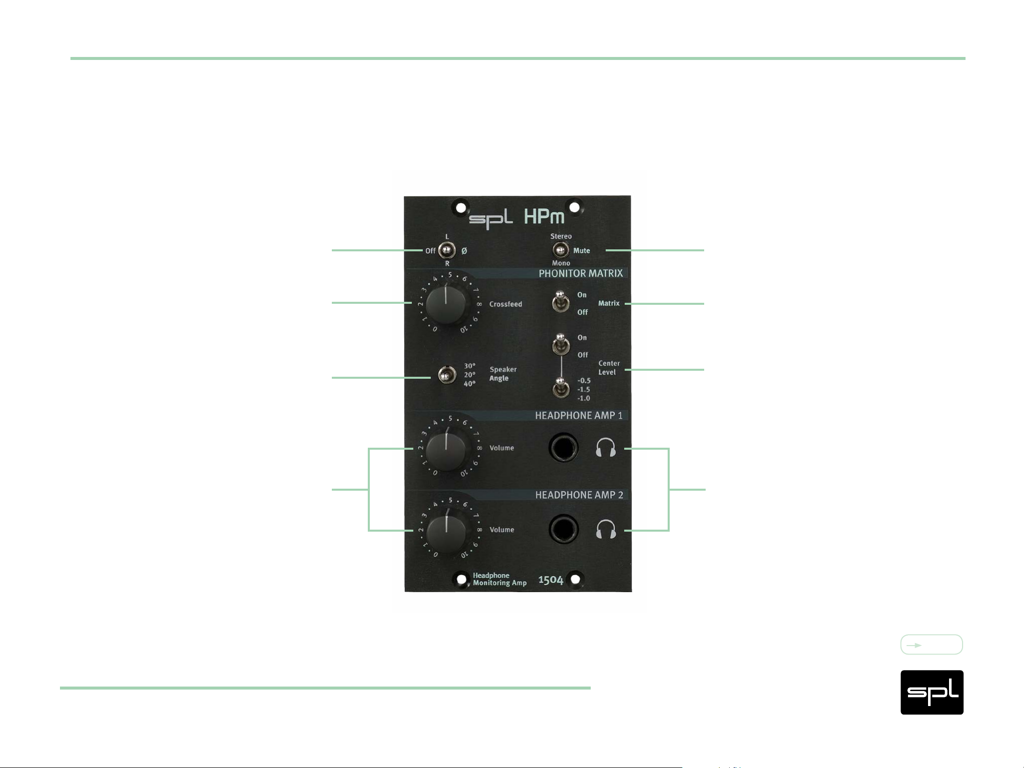
Control Elements
Phase Inversion Ø
Stereo/Mono/Mute
Phonitor Matrix
Center Level
Headphone Jacks
Crossfeed
Speaker Angle
Volume
HPm
Content
8
Page 9

Phase Inversion Ø
With the Phase Inversion switch you invert the phase of the left or the right channel
(180°). In position “L” the phase of the left channel is inverted. In position “R” the phase
of the right channel is inverted.
In position “Off” no channel is phase inverted.
The phase inversion is used to check whether phantom center signals are precisely
positioned in the stereo center. Invert the phase of one channel and engage mono. All
Control Elements
phantom center signals should disappear.
Content
HPm
9
Page 10

Crossfeed
The Crossfeed defines the interaural level difference. It approximates the influences of
room size, reflections and absorption characteristics of the room your speakers are in.
The higher the Crossfeed the more the stereo image is shrinking. To mimic a dry room
use lower Crossfeed settings whereas to mimic a wet room the Crossfeed should by set
to higher values.
See also “Phonitor Matrix” on page 17 cont.
Control Elements
Youl’ll find more information about the setting of Crossfeed and Speaker Angle under
“Setting of Crossfeed and Speaker Angle” on page 20.
Content
HPm
10
Page 11

Speaker Angle
With the Speaker Angle switch you adjust the interaural time difference which is related
to the placement of the speakers.
You can choose one of three angle values: 20°, 30° and 40°.
See also “Phonitor Matrix” on page 17 cont.
Youl’ll find more information about the setting of Crossfeed and Speaker Angle under
“Setting of Crossfeed and Speaker Angle” on page 20.
Control Elements
HPm
Content
11
Page 12

Volume
With these two detended controls you regulate the amplification for each headphone
output individually.
Control Elements
HPm
Content
12
Page 13

Stereo/Mono/Mute
The headphone playback can be switched between Stereo and Mono. In the Mute position no signal passes through to the headphones.
In Mono position the Mono compatibility can accustically be checked. Voices and instruments which appear quieter or disappear completely in mono have phase problems
within the stereo signals.
The phase inversion is used to check whether phantom center signals are precisely
Control Elements
positioned in the stereo center. Engage mono and invert the phase of one channel. All
phantom center signals should disappear.
Content
HPm
13
Page 14

Matrix On/Off
With the Matrix switch you activate or deactivate the Phonitor Matrix (Crossfeed, Speaker
Angle and Center Level).
If switched off the settings of Crossfeed, Speaker Angle and Center Level have no influence
on the headphone playback and the HPm operates as a “normal” headphone amplifier.
Control Elements
HPm
Content
14
Page 15

Center Level
With the Center Level you control the monitoring intensity of the signals positioned in
the phantom center.
If the stereo width is narrowed through changes in Crossfeed and Speaker Angle (so as
to correspond to your actual loudspeaker setup), the phantom center may likely sound
too intense while mixing on headphones. You normally would counteract by lowering
the phantom center signals in the mix. When listening to that mix on loudspeakers the
phantom center appear to quiet.
Control Elements
Therefore Center Level gives you the possibility to lower the phantom center playback
level by 0.5, 1.0 or 1.5 dB. The phantom center gains the correct level in relation to the
L/R stereo image on loudspeakers.
Content
HPm
15
Page 16

Headphone Jacks
Connect headphones to the standard 1/4” (TRS) stereo jack plugs.
Warning: Never connect a mono jack cable to the headphone output (front
panel stereo jack). Make sure that the stereo jack is fully inserted, otherwise
a short circuit might damage the headphone amplifier!
Control Elements
HPm
Content
16
Page 17

Basics of stereo listening
When listening to speakers sound coming from the right is not only perceived with the
right ear (red line) but it is also perceived with the left ear (green line). The sensation
is time delayed, lower in level and has a reduced frequency range (this applies to the
left speaker accordingly).
Sound from the right side Sound from the left side
Phonitor Matrix
It arrives later because the signal travels a distance of approx. 340 meters per second and the distance from the
right speaker to the left ear is longer than it is to the right ear. It is quieter and does not deliver the full frequency
range, because the signal of the right speaker does not directly arrive at the left ear but is partially reflected and
absorbed by the head.
HPm
Content
17
Page 18

Our brain determines the direction of the sound by perceiving the time delay (interaural
time difference) and the level difference (interaural level difference).
Stereo listening with a “traditional“ headphone pre-
amplier
When listening to music with a “traditional” headphone amplifier, the right ear only
perceives the right signal (red line) and the left ear only perceives the left signal (green
Phonitor Matrix
line).
In contrast to listening to speakers the delayed and quieter signal of the respective
opposite side is missing.
As a result to this super-stereo-effect reverb and delay effects as well as EQ and panorama adjustments are perceived more intense resulting in an exaggerated playback
on headphones which does not represent the music as approoved by the artist and
producer.
Content
HPm
18
Page 19

How does the Phonitor Matrix work?
The Phonitor Matrix calculates the interaural time difference (Speaker Angle) and interaural level difference (Crossfeed) with their specific frequency responses to deliver a
speaker-like listening experience on headphones.
The super-stereo-effect is eliminated and all reverb and delay effects as well as EQ and
panorama adjustments are perceived correctly on headphones.
The headphone mix therefore translates well to speakers.
Phonitor Matrix
An analog filter design creates interaural time and level differences for three different
speaker placements. This analog filter design is controlled by the crossfeed and angle
parameters.
Content
HPm
19
Page 20

Setting of Crossfeed and Speaker Angle
Both parameters (Crossfeed and Speaker Angle) define the interaural level difference
and the interaural time difference.
To reproduce the exact placement of the loudspeakers, first choose the Speaker Angle
parameter representing your real speaker placement.
Then play some audio you know well. Adjust the Crossfeed until the headphone playback
comes closest to your loudspeaker listening experience.
Phonitor Matrix
20°20°
30°30°
40°40°
Content
HPm
20
Page 21

Exclamation mark within a triangle
An exclamation mark within a triangle is intended to make you aware of important operational advice and/or warnings that must be followed.
Be especially attentive to these and always follow the advice they give.
Lightning symbol within a triangle
Symbols
In this Manual a lightning symbol within a triangle warns you about the potential for
dangerous electrical shocks – wich can also occur even after the device has been disconnected from a power source.
Symbol of a lamp
The symbol of a lamp directs your attention to explanations of important functions or
applications.
Content
HPm
21
Page 22

Connections
Only use the connections as described.
Other connections can lead to health risks and damage the equipment.
Water and humidity
Do not use this device anywhere near water (for example in a bathroom, a damp cellar,
Security Advices
near swimming pools, or similar environments). Otherwise your are dealing with an
extremely high risk of fatal electrical shocks!
Insertion of objects or uids
Be careful to not insert any object into any of the chassis openings. You can otherwise
easily come into contact with dangerous voltage or cause a damaging short circuit.
Never allow any fluids to be spilled or sprayed on the device. Such actions can lead to
dangerous electrical shocks or fire!
Content
HPm
22
Page 23

Air ventilation
Chassis openings offer ventilation and serve to protect the device from overheating.
Never cover or otherwise close off these openings. Never place the device on a soft
surface (carpet, sofa, etc.).
Electrical power
Operate the device only from power sources that can provide proper power. When in
Security Advices
doubt about a source, contact your dealer or a professional electrician. To be certain
you have isolated the device, disconnect all power and signal connections. Make sure
that the power supply plug is always accessible. When not using the device for a longer
period, make sure to unplug it from your wall power socket.
Opening the unit
Simply put: DON’T, if you are not a certified SPL technician or engineer. Really: Do not
open the device housing, as there is great risk you will damage the device, or – even
after being disconnected – you may receive a dangerous electrical shock.
Content
HPm
23
Page 24

Power connection overloads
Avoid any kind of overload in connections to wall sockets, extension or splitter power
cords, or signal inputs. Always keep manufacturer warnings and instructions in mind.
Overloads create fire hazards and risk of dangerous shocks.
Lightning
Security Advices
Before thunderstorms or other severe weather, disconnect the device from wall power;
do not do this during a storm in order to avoid life threatening lightning strikes.
Similarly, before any severe weather, disconnect all the power connections of other
devices and antenna and phone/network cables which may be interconnected so that
no lightning damage or overload results from such secondary connections.
Content
HPm
24
Page 25

Controls and switches
Operate the controls and switches only as described in the manual. Incorrect adjustments
outside safe parameters can lead to damage and unnecessary repair costs. Never use
the switches or level controls to effect excessive or extreme changes.
Repairs
Unplug the unit from all power and signal connections and immediately contact a quali-
Security Advices
fied technician when you think repairs are needed – or when moisture or foreign objects
may accidentally have reached inside the housing, or in cases when the device may have
fallen and shows any sign of having been damaged. This also applies to any situation in
which the unit has not been subjected to any of these unusual circumstances but still
is not functioning normally or its performance is substantially altered.
In cases of damage to the power supply and cord, first consider turning off the main
circuit breaker before unplugging the power cord.
Content
HPm
25
Page 26

Replacement/substitute parts
Be sure that any service technician uses original replacement parts or those with identical specifications as the originals.
Incorrectly substituted parts can lead to fire, electrical shock or other dangers, including
further equipment damage.
Safety inspection
Security Advices
Be sure always to ask a service technician to conduct a thorough safety check and ensure
that the state of the repaired device is in all respects up to factory standards.
Cleaning
Do not use any solvents, as these can damage the chassis finish.
Use a clean, dry cloth (if necessary, with an acid-free cleaning oil).
Disconnect the device from your power source before cleaning.
Content
HPm
26
Page 27

© 2016 SPL electronics GmbH
The content of this document is protected under copyright law. This document is the
property of SPL and may not be copied or reproduced in any manner, in part or fully,
without prior authorization by SPL. Sound Performance Lab (SPL) continuously strives
to improve its products and reserves the right to modify the product described in this
manual at any time without prior notice.
SPL and the SPL Logo are registered trademarks of SPL electronics GmbH. All company
names and product names in this manual are the trademarks or registered trademarks
of their respective companies.
Declaration of CE Conformity
The construction of this unit is in compliance with the standards and regulations of the
European Community.
HPm
Content
27
Page 28

Notes on Environmental Protection
At the end of its operating life, this product must not be disposed of with regular household waste but must be returned to a collection point for the recycling of electrical and
electronic equipment.
The wheelie bin symbol on the product, user’s manual and packaging indicates that.
The materials can be reused in accordance with their markings.
Through reuse, recycling of raw materials, or other forms of recycling of old products,
you are making an important contribution to the protection of our environment.
Your local administrative office can advise you of the responsible waste disposal point.
WEEE Registration: 973 349 88
HPm
Content
28
Page 29

Contact
SPL electronics GmbH
Sohlweg 80
41372 Niederkrüchten
Germany
Phone +49 2163 9834-0
Fax +49 2163 9834-20
E-Mail: info@spl.info
Contact
Or follow us on our Blog, Facebook, Twitter and YouTube:
Website & Blog: spl.info
Videos: youtube.spl.info
Twitter: twitter.spl.info
Facebook: facebook.spl.info
HPm
Content
29
 Loading...