

Page 1
SOUND PERFORMANCE LAB
model 9735
Manual
DynaMaxx
Compressor, Limiter, Noise Gate
and De-Compressor
Page 2
By Hermann Gier,Paul Lentzen and Paul White
Version 2.0 - 05/1998
The information in this document has been
carefully verified and is assumed to be correct.
However Sound Performance Lab (SPL)
reserves the right to modify the product
described in this manual at any time. Changes
without notice.This document is the property
of SPL and may not be copied or reproduced
in any manner, in part or full without the
authorisation of SPL.
Limitations of Liability:
In no event will SPL be liable for any
damages, including loss of data, lost profits,
cost of cover or other special, incidental,
consequential or indirect damages arising
from the use of the unit, however caused and
on any theory of liability. This limitation will
apply even if SPL or an authorised dealer has
been advised of the possibility of such
damage.
SPL electronics GmbH
Office address: Sohlweg 55
D-41372 Niederkruechten, Germany
Postal address:P.O.Box 12 27
D- 41368 Niederkruechten, Germany
Phone +49 - 21 63 / 98 34-0
Fax +49 - 21 63 / 98 34-20
E-mail: info@spl-electronics.com
www.spl-electronics.com
© 1999 SPL electronics GmbH. All rights reserved.
DynaMaxx
Model 9735
Owner´s Manual
SOUND PERFORMANCE LAB
Page 3

DynaMaxx
3
Contents
I would like to start with my thanks to all our staff, who created
what is to be described here.The importance of their exceptional
qualification and talents cannot be overestimated.Special thanks
go to Ruben Tilgner for his extraordinary work on time constants
automation.
Our products are often tested and compared in many publications and by our customers themselfs and constantly valued with
best results. I would like to pass on this broad appreciation to
those,who deserve it – my excellent colleagues.
Hermann Gier
Foreword
Thanks
Foreword .................................................................................................. 3
Thanks ....................................................................................................... 3
Introduction ............................................................................................ 4
Operation Safety ..................................................................................... 5
Connections ............................................................................................ 6
Tech Talk ................................................................................................... 7
Full-Band versus Multi-Band ............................................................. 8
Dynamic Intelligence: Attack time automation ......................... 8
Dynamic Intelligence: Release time automation .......................10
Threshold and Ratio ............................................................................10
Double VCA-Drive Technology
TM
......................................................11
Control Elements ..................................................................................12
ACTIVE .....................................................................................................12
Sig.LED ....................................................................................................12
COMPRESS ..............................................................................................12
GAIN .........................................................................................................13
SOFT LIMIT ..............................................................................................14
EFFECT-COMPRESSION ......................................................................15
DE-COMPRESSION ...............................................................................15
LED-Display.............................................................................................17
NOISE GATE ............................................................................................17
SIDE CHAIN .............................................................................................17
STEREO COUPLE ...................................................................................18
Power supply............................................................................................18
Specifications...........................................................................................19
Warranty ....................................................................................................20
Dear customer,
Thank you for the confidence you have shown towards SPL elec-
tronics GmbH by purchasing the SPL D
YNAMAXX.You have decided
to use a tool of high performance which sets you in the position
to have faster success and a better sound quality in your music
productions, live sound applications and pre-masterings. As a
typical SPL unit the D
YNAMAXX combines exemplary specifications
and high manufacturing standard with excellent sound quality to
provide you a precious component for recording purposes.
Please read this manual carefully to ensure you have all the
information you need to use the D
YNAMAXX. We wish you every
success with your new D
YNAMAXX.
Your Sound Performance Lab-Team
Page 4

DynaMaxx
4
Part of the SPL Analog-Blue series, the DYNAMAXX is a new type
of dynamics processor that has both corrective and creative
applications in those areas normally addressed by conventional
compressors. In keeping with the SPL design philosophy,it incorporates many new features not found on standard compressors,
and a slightly unconventional approach to the control system
makes is surprisingly easy to use.
D
YNAMAXX also premiers a new facility, the DE-COMPRESSOR,
which may be used to counter the effects of overcompression in
previously processed source material. D
YNAMAXX can be used to
provide unobtrusive compression and limiting at the premastering stage,or to produce creative compression effects.
Why is D
YNAMAXX so different? Though auto attack and release
functions are nothing new, in the D
YNAMAXX design, the time
constants are automated in a very musical way.D
YNAMAXX adapti-
vely and intelligently optimizes all time constants in real time
during processing so that the compression characteristics are
continually matched to the source material. D
YNAMAXX is also the
first compressor to make use of the new THAT 2181 VCAs, and the
circuit actually uses two of these excellent VCAs in SPL’s Double
VCA-Drive
TM
mode configuration, which doubles the operating
range while increasing transparency and reducing distortion.
A benefit of the D
YNAMAXX circuit is that high compression ratios
do not affect high frequency detail – high amplitude, low-end
bass can be controlled without introducing pumping or other
negative side-effects. Similarly, complex stereo sources can be
processed easily and very musically. D
YNAMAXX has numerous
applications in recording and mixing, as well as for cost-effective
stereo mastering, and because of the level of intelligent processing within the unit, there are only two controls to adjust per
channel,making operation very intuitive.
CONTROL OVERVIEW
COMPRESS:
Sets the amount of compression, while the degree of gain reduction is continually monitored via the LED meters.
GAIN:
This is similar to the ‘make-up’gain control used on conventional
compressors and is provided to restore signal levels that have
been reduced by the compressor action. This control also
compensates for any gain increase in DE-COMPRESSION mode.
The control has a range of 20dB.
SOFT LIMIT:
Switches between COMPRESSION and SOFT LIMIT mode
featuring a gentle soft-knee-characteristic to minimize audible
side effects.
EFFECT COMPRESSION:
In this mode, the Release time is set to a fixed 60ms to produce a
'vintage compression' effect that works well on solo instruments
and occasionally voices.
Introduction
The DYNAMAXX is a new type of
compressor-limiter.
D
YNAMAXX premiers a new func-
tion: the DE-COMPRESSOR.
D
YNAMAXX adaptively and
intelligently optimizes all time
constants while processing so
that you gain optimum
compressor performance
throughout a song.
D
YNAMAXX is the first compressor
to use the new THAT 2181 VCAs
– in SPL’s Double VCA-Drive
TM
mode.
The applications are in recording,mixing,and mastering.
Page 5
DynaMaxx
5
Operation Safety
DE-COMPRESSION:
converts the compressor to an intelligent upward expander that
allows you the de-compress highly compressed audio signals,
such as samples, keyboards sounds or previously recorded tracks
that have been overcompressed. For example, the sounds used in
most drum machines are highly compressed, but processing
them via the De-compress mode restores their dynamics and
vitality.
Each channel incorporates a NOISE GATE with ARC (AutoRelease-Circuitry), and this too is highly automated. In a mastering situation, it may be used to provide click-free gating at the
beginning and the end of a song.The CLOSE-LED indicates when
the NOISE GATE shuts.
Both channels of D
YNAMAXX are equipped with a 20-digit LED
ladder meter displaying gain changes to a resolution of 1dB.The
displayed values range from -10dB to +9dB.
Each channel also has an additional SIGNAL-LED which illuminates when the input signal is hotter than -40dB.
If it is required to patch in external processing, both left and
right channels have SIDE CHAIN inputs.If an acceptable sidechain
signal is being received,a LED on the front illuminates.
When processing stereo material, the STEREO COUPLE function
should be switched on so that both channels produce the samedegree of gain change. This is necessary to maintain a coherent
and stable stereo image. The front panel controls, including the
ACTIVE switch of channel 1,function as master controls in STEREO
COUPLE mode.
The housing of the D
YNAMAXX has the standard 19"- EIA format
and occupies 1U (44.45 mm) in your rack.When installing the unit
in a 19"-rack,the rear side of the unit needs some support,especially in a touring case.
The D
YNAMAXX should not be installed near units which produce
strong magnetic fields or extreme heat. Do not install the
D
YNAMAXX directly above or below power amplifiers.
Check that the voltage details quoted on the back panel are the
same as your local mains electricity supply. Use a minus (-)
screwdriver to set the voltage selector to the voltage for the area
in which the unit will be used.
Never cover up the ventilation slots on the top of the unit. If,
during operation,the sound is interrupted or indicators no longer
illuminate, or if abnormal odor or smoke is detected, or if liquids
are spilled on the unit, immediately disconnect the power cord
plug and contact your dealer.
Only clean your D
YNAMAXX with a soft, lint-free cloth.
Regain vitality and dynamics
from highly compressed
audio files
NOISE GATE with new “Auto
Release Circuitry”
20-digit metering with 1dB
resolution
SIDE CHAIN inputs for external
filtering or triggering
STEREO COUPLE mode
Page 6
DynaMaxx
6
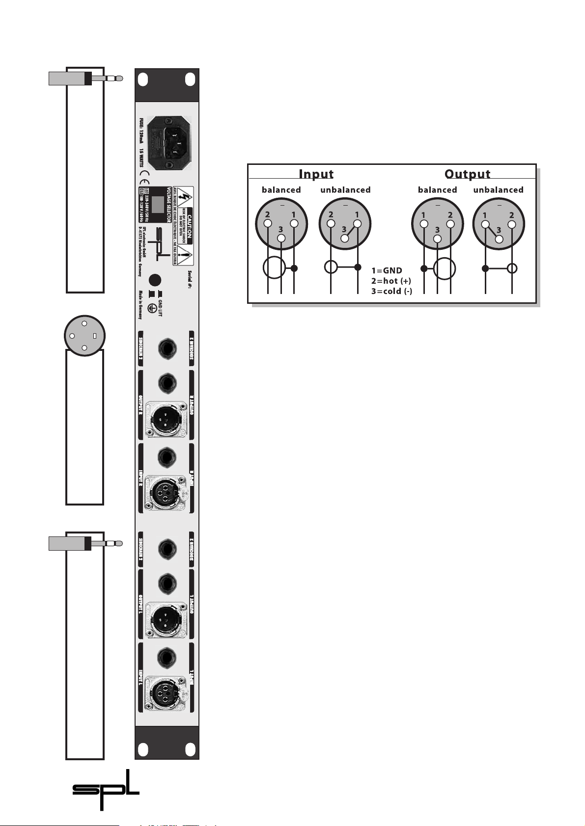
Connections
DYNAMAXX is fitted with both XLR-connectors and TRS stereo
jacks for balanced operation, though the jacks may be used with
unbalanced connections simply by plugging in mono jack-plugs.
The level difference that normally occurs when a balanced input
or output is used unbalanced is automatically compensated for.
Should the need arise to use the XLR connectors in an unbalanced system, pin 3 of the XLRs should be grounded. Inserting a
mono jack also unbalances the XLRs.
Both output stages operate in parallel, so it is possible to
connect two different destination units simultaneously, for
example to record to two different media at the same time or split
the output between a mixer and effects processor. However,only
one type of input (jack or XLR) should be connected at a time –
the D
YNAMAXX is not intended to be used as a mixer!
To ensure optimal signal quality, SPL has developed a new
hybrid-component balanced input/output stage using all lasertrimmed resistors with a tolerance of 0.01%. This approach has
resulted in an exceptionally high CCMR (common mode rejection:
-80 dB at 1kHz). As a precaution, before connecting the D
YNAMAXX
switch off the power to the unit and to all connected units.
SIDE CHAIN
Each D
YNAMAXX channel is equipped with a TRS jack sidechain
insert point so that an equalizer may be inserted to provide
frequency dependant processing. Connection requires only a
conventional insert Y-lead, where the TRS ring connection
provides the insert send signal and the tip the return. The front
panel LED lights when the side chain signal is of adequate level.
For example: Frequency dependent filtering
Connect the TRS jack to the Side Chain connector of the
D
YNAMAXX. The ring of the TRS jack carries the original signal into
the D
YNAMAXX to the input of the equalizer.The equaliser´s output
is returned to the D
YNAMAXX on the tip of the jack plug. A LED on
the front illuminates when a sidechain signal is present.
Other rear panel connections and switches:
• Voltage selector: 220-240V/50Hz or 100-120V/60Hz
• VDE/CSA/UL approved 3-pole power plug
• GND-Lift switch
1
2
3
Pin wiring: XLR connectors
1=GND 2=Hot(+) 3=Cold(-)
Pin wiring: Stereo Jack plug
Tip=Hot(+) Ring=Cold(-) Sleeve=GND
Pin wiring: Side Chain-Insert
Tip=Return (in) Ring=Send (out) Sleeve=GND
Page 7

DynaMaxx
7
What are compressors doing?
A brief description of the
well-known problems with
standard compressors
Static or fixed time constants
are responsible for the nega-
tive side-effects.Music is not
static and the attack and
release parameters of instru-
ments or vocals change
throughout a song.
D
YNAMAXX ingeniously adapts
the time constants to the
music and generates better
compression set-ups than
standard compressors.
This section deals with the technical background of the
D
YNAMAXX and explains why we felt it necessary to do some things
rather differently to the way other manufacturers do them. We
will also explain the benefits of the D
YNAMAXX design.
Generally, the function of an audio compressor is to compress
the dynamic range of the source signal by altering the gain of its
signal path in response to the relative level of the signal as
compared to an arbitrary threshold level. In effect, this process
can be thought of as providing additional gain to low-level
signals or reducing gain in the presence of high-level signals.
Why are conventional compressors unsatisfactory?
One of the main difficulties in setting up a compressor is choosing the time constants Attack, Decay, Sustain, and Release (in
short: ADSR). The most important time constants are Attack and
Release – in the context of gain control, Decay and Sustain are
generally fixed and in any event, they tend to play a minor role.
The inappropriate choice of time constants is mainly responsible
for the familiar pumping or breathing effects, though this effects
may be deliberately sought for creative applications. Unless the
attack time is set to be very short, fast transient attacks may get
through the system,because the compressor response is too slow
to bring them under control.
Threshold and Ratio are easier to set up, but when high
compression ratios are used, high frequencies tend to become
overcompressed,which makes the material sound dull or lacking
in presence. It is normal to set up compressors based on the
loudest peak in the program material, in which case the parameters are optimised for this moment in time only. The rest of the
time, the time constants are less than optimal. Taking into consideration that each musical instrument has varying attack and
release times, depending not only on the character of the instrument,but also on the way it is played, you can see that it is almost
impossible to choose a set of fixed parameters that will be correct
for an entire piece of music.
In modern music productions,vocals are often recorded directly
to a digital format, which means that gain control is very important due to digital systems’inability to tolerate excessive levels. It
is extremely important to compress or limit the vocal part during
recording so as to make the best possible use of the available
digital headroom while preventing digital clipping. Vocals can
have an extremely wide dynamic range, especially in the case of
untrained pop singers, so for the best results, it may become
necessary to re-adjust the compressor settings while recording.
The D
YNAMAXX solves these problems by the use of intelligent
automation – the compressor’s time constants are re-adjusted
adaptively in response to the changing dynamic characteristics of
the music.In other words,D
YNAMAXX intelligently optimizes Attack
and Release times on the fly,which is why the control system is so
simple. Both Threshold and Ratio are combined within the
COMPRESS-control,and the advanced Double VCA Drive
TM
Techno-
logy maintains signal clarity,even at high levels of compression.
Tech Talk
Page 8

DynaMaxx
8
Multi-band compressors split
the input in several bands to
overcome pumping effects.
Mixing the bands back
together creates phase intermodulations resulting in
audible sound colouration and
loss of dimensions.
The full-band technology of
D
YNAMAXX does not reduce
dimensions and avoids
incoherence and
sound colouration.
D
YNAMAXX can be set up much
faster than a Multi-band
system.
An example illustrates the
problems of adjusting the
Attack time.
Full-Band versus Multi-Band
Some compressors try to solve the problem of high frequencies
being modulated by low frequency compression by moving to a
split band system,so why don't we do that?
Multi-band compression seems like a good idea to overcome
the pumping effects caused by heavy bass compression also
causing high frequency sounds to be pulled down in level. For
example, with a regular compressor, you may be compressing a
bass-drum but the Release time is set a little too long with the
result that the following hi-hat gets ducked in level. Multi-band
technology splits the original signal into two or more bands to be
processed individually, and in this way, heavy gain reduction at
the bass end doesn’t affect the level of the high frequencies.The
problem is that unless the design is very elaborate and well
thought out, phase differences and other problems can occur
between the bands, resulting in a less natural sound or in an
obviously processed sound (“radio sound”).
Until now, you had to choose between using a conventional
full-band compressor or a multi-band design, but D
YNAMAXX
works differently from either and has significant advantages over
both.
The secret is D
YNAMAXX’s new Double VCA Drive Technology
TM
using the excellent „2181 Super-VCAs“ from THAT Corporation,
and in addition to a very clean signal path, it provides two main
advantages:
1. As explained, Multi-band technology has a significant sonic
short-coming due to the way the original signal has to be split up
into various bands, compressed, then mixed back together in a
summing stage. Due to different levels of processing within the
various bands, each band’s output may be changed in phase
response, so that when the bands are recombined, the signal
tends to have reduced dimensions and sounds incoherent and
coloured.Because D
YNAMAXX doesn’t split the signal into separate
frequency bands,this problem is avoided.
2. D
YNAMAXX offers simplicity of control. With Multi-band
systems you have to set all the time constants plus GAIN,
Threshold, and Ratio for each band. With a fully manual FourBand-compressor, this would mean 20 parameters to set up per
channel.D
YNAMAXX only needs 2!
Dynamic intelligence: Attack time automation
How does DynaMaxx adjust the Attack time?
To understand this, it’s first necessary to see what happens when
a compressor is used with a fixed Attack time setting. For
example, the sound of low bass guitar note can either come in
smoothly (especially with fretless basses), or with a very fast transient attack when slapping or popping playing techniques are
used. If the Attack time is set to minimum (very short), the
compressor is able to catch the peak of the transient attack but
Page 9

DynaMaxx
9
any closely following notes will suffer increased transient distortion because the control voltage within the compressor rises
further as successive notes are processed.This behaviour is sometimes described as ‘surfing’, and can be overcome by setting a
lightly longer attack time, but now some peaks get through
because they are faster than the compressor’s Attack time. This
problem is widely appreciated,which is why many manufacturers
include a separate Peak-Limiter to catch those fast transients that
the compressor is unable to control. If this is done using two VCA
stages, the signal undergoes more quality degradation than is
desirable, but even with designs that use the same VCA for both
compression and limiting, you still end up with more controls
than necessary.
D
YNAMAXX doesn’t need a separate Peak-Limiter, because it
detects very fast transients automatically and activates a second
and faster attack time circuitry. This ensures that no peaks slip
through,but the speed of activating the second attack stage is so
fast that all signals stay within the soft-knee curve for a more
natural sound. To activate the second stage, D
YNAMAXX conti-
nuously compares the output of the Attack time control stage
with the input of Attack time control stage. If the comparison
reveals that a fast transient has slipped through the first Attack
time control stage, a second, much faster Attack time control
stage is immediately activated to catch the peak. D
YNAMAXX uses
12 dB/octave filtering instead of the 6 dB/octave filtering used in
standard compressor side-chains so as to increase the precision
and speed of transient detection and processing.
How does this work?
D
YNAMAXX can reduce its Attack time in the instant of a percussive
hit or bass guitar slap to a minimum of 50 microseconds. As soon
as the peak is passed,the attack returns to a longer time constant
(up to 10ms of first Attack time circuitry), and in this way, both
pumping and distortion are avoided.
The ability of D
YNAMAXX to respond so quickly to changes in
program dynamics is clearly valuable when complex stereo mixes
are being treated. If, for example, a snare drum peak occurs,
D
YNAMAXX rapidly changes to a very short Attack time so that the
snare hit keeps its original transient characteristics rather than
sounding ‘softened’. Following signals are compressed using
longer Attack times to minimize distortion and surfing – short
attacks are only brought in when necessary to deal with fast, high
level transients. If D
YNAMAXX is operated in its normal compres-
sion mode, breathing and pumping effects are unlikely to be
encountered, so this is the mode to select when compression is
being used purely to control levels and to compress the dynamic
range of the source material.
If pumping effects are needed for creative reasons, you have
the option either to turn COMPRESS control to maximum and/or
switch the unit into EFFECT COMPRESSION mode. For heavier
effects,you can also depress the SOFT LIMIT switch.
- Attack too fast: adds distortion plus “surfing“-effects
- Attack too slow: peaks slip
through
D
YNAMAXX’S Attack time re-
adjustment is fast enough to
make an additional Peak-
Limiter redundant
D
YNAMAXX automatically
adapts the Attack times to the
characteristics of the music:
- fast transients: fast Attack
times (> 50 µs)
- slow transients: slow Attack
times (<10 ms)
Page 10

DynaMaxx
10
Dynamic intelligence: Release time automation
How does DynaMaxx adjust the Release time?
Again, it is beneficial to look at what happens when the Release
time is too short: In this case the compressor will restore normal
gain conditions as soon as the peak has passed, and this rapid
increase in gain is what we call breathing. Breathing is especially
annoying during a part with soft strings or low level layered
sounds – whenever a peak comes along, the strings duck down
with it, only to pump up again when the peak is over. Sonically
the sound image swims and pumps while the subjectively
perceived loudness remains at a low level.
D
YNAMAXX uses a special technique to overcome these
problems. First it monitors the average music level. If a loud transient sound occurs (bass drum, snare and so on) that also has a
big gain step,a very short Release time is set and the signal level
is reduced to the calculated average music level,not to the threshold! If the compressor reduces the level to the Threshold (which
is what standard compressors do), you would again hear
pumping effects,because of the way low-level signals are lifted in
gain.
The Release time is controlled depending on the difference
between the actual peak and calculated average signal levels.If a
large difference is detected, D
YNAMAXX will set a faster Release
time, whereas if only a small level difference is detected,
D
YNAMAXX will release more slowly.The Release time setting is, in
effect, controlled by an RC-based analogue computer that dynamically calculates the various Release times.
Threshold and Ratio
Threshold and Ratio are both set by the COMPRESS control;
using a low setting for the COMPRESS control causes only the
peak levels to be compressed,because the Threshold is relatively
high. For more compression, turning the control clockwise has
the effect of lowering the Threshold to include more low-level
signals in the processing.As the Threshold is lowered,the Ratio is
simultaneously increased, and the fully clockwise position is
equivalent to a Ratio of around 3:1. However, the Threshold and
Ratio values are not static, but rather vary depending on the
attack and level characteristics of the source signal. Peak levels
are automatically compressed with a higher Ratio to maintain
control over maximum signal levels, but still using an unobstrusive soft-knee compression characteristic.
D
YNAMAXX calculates
“Multi-Release-Times“:
• Big and fast Gain changes:
fast Release times
• Small and slow Gain changes:
slow Release times
The D
YNAMAXX doesn’t use static
Threshold and Ratio values –
they vary depending on the
attack and level characteristics
of the source signal.
Page 11

DynaMaxx
11
SPL’s Double VCA Drive Technology
TM
Double VCA Drive TechnologyTMutilizes two VCAs per audio
channel, where one VCA handles positive current and the other
negative.This way, the control voltage can effectively be halved,
but the amount of gain change can be doubled. The benefit of
this configuration is that the transistors within the VCAs don’t run
into saturation problems,which in turn avoids offset noise, generally audible as clicks and pops.
Compared with the acclaimed DBX 2150 VCA, the new THAT
2181 VCA is less sensitive to offset noise, and the Double VCA
Drive configuration produces extremely good audio performance, both subjective and measured. The diagram illustrates
the principle of this circuit:
The audio signal is split in two paths, one of which is phase
inverted, and after having passed through the VCAs, the two
signals are recombined in a differential amplifier. This topography causes a cancellation of negative side effects, mainly
distortion and sound coloration, by the mechanism of common
mode rejection (CMRR > 50 dB) within the differential amp. At the
same time the original audio signal is increased in level by 6 dB.
What are the practical advantages?
Clearly one cannot expect the noise floor of the VCAs to be
reduced by 50 dB, because noise is a non-correlated signal, but
taking into account the 6dB signal boost, the noise floor is
improved by 3dB.
However, the real benefit is the reduction in THD (Total
Harmonic Distortion). Although the THD spectrums of positive
and negative half cycles are not identical, a significant degree of
cancellation nevertheless takes place, and the residual THD is
right at the limits of available measuring equipment.The same is
true of intermodulation distortion and control voltage crosstalk,
both of which are cancelled in the differential amplifier stage.
Diagram:
SPL’s Double VCA Drive
Technology
TM
SPL’s Double VCA Drive
Technology
TM
and the new
„2181 Super-VCA“ from THAT
Corporation double the opera-
ting range,realize extremely low
noise and distortion figures as
well as a unique sound quality.
Page 12

DynaMaxx
12
Relay hard-bypass XLR and jack
inputs and outputs
Control Elements
The ACTIVE switch operates a hard-bypass relay circuit to switch
the channel in and out of processing and a status LED indicates
that the channel is active.
The unit also switches to relay hard-bypass automatically in the
case of a power failure,either on the primary or secondary side of
the power supply, or when the unit is turned off at the POWER
SWITCH.
If the D
YNAMAXX is operated in the STEREO COUPLE mode (see
11),channel one’s ACTIVE switch also switches channel two in and
out. Note that channel two’s ACTIVE status-LED will also follow
channel one’s ACTIVE switch status.
Each channel is equipped with a SIGNAL LED (Sig.LED) that illuminates when the input signal exceeds -40dB.This is primarily an
aid to setting up, and confirms a suitable input level,either when
first adjusting the D
YNAMAXX, or when inserting the unit into a
new signal path.
The COMPRESS control sets the compression intensity by
varying both Threshold and Ratio simultaneously. Choosing low
settings for the COMPRESS control will cause D
YNAMAXX to
operate as a peak compressor – as the Threshold is relatively high,
only the peak levels are processed. For more compression turn
the control clockwise, which lowers the Threshold and increases
the ratio,thus extending the processing to lower level signals.The
fully clockwise position is equivalent to a Ratio of 3:1, and the LED
display (5) shows the equivalent gain reduction.
Active
1
2
Signal LED
3
Compress
1
5
7
3
9
11
4
6
8
10
2
Page 13

DynaMaxx
13
Diagram 1:
Normal Compression mode
COMPRESS control s set to three
values: 2,4,and 7
GAIN set to 0 dB
As with any compressor, the overall signal level decreases with
increasing compression, so the GAIN control is used to compensate for this (also see 4).To compare input and output levels more
accurately, monitor a precise PPM metering and set the GAIN
control to a position where both the input and output peak levels
are identical. This allows subjective judgements to be made
concerning the increase in apparent loudness caused by the
compression process.
Examples on setting COMPRESS control
1.You want to compress your program material only gently: Turn
the COMPRESS control clockwise until the Gain Reduction LED
ladder shows a peak level reduction of between 2 and 3dB.
Turning the COMPRESS control further clockwise will lower the
Threshold to include more low-level signals into the compression
process.
2.Your audio source contains several amplitude peaks,but each
peak has a different characteristic, so to obtain optimum results
with a conventional device, it would normally be necessary to
adjust the compressor during operation. D
YNAMAXX performs this
adjustment automatically so that peak levels are reduced according to both their actual peak level and their attack and release
characteristics. The following diagram shows the gain control
curve in normal compression mode. For better readability of the
graph, the gain has been kept at 0dB,so no compensation for the
gain reduction is applied.
The GAIN control compensates for any level decrease when
applying COMPRESSION, EFFECT COMPRESSION (6), or SOFT
LIMITING (5). The higher the processing intensity the lower the
overall output level,the more Gain will be required to restore the
same peak level.
Gain
4
Page 14

DynaMaxx
14
Turn the GAIN control clockwise until the peak level of the input
is the same as the peak level of the output.If you use D
YNAMAXX in
a premastering application, you can use the LED display to
evaluate the increase in subjective loudness.To do this, locate the
highest peak level within the source material, and after having
applied the desired degree of compression, set the GAIN control
so that the peak level is reduced to 0 dB. For all lower-level
sections of the material, the LED display shows the added
loudness.
If the DE-COMPRESSION mode is active (7), the GAIN control
compensates for the increase in peak level. Note that in this
mode, turning the GAIN control clockwise decreases the output
level.
The control has a range of 20 dB.
In SOFT LIMIT mode, D
YNAMAXX only processes the peak levels
but leaves the gain structure of low-level signals unchanged.
SOFT LIMIT mode is useful when recording on ‘clipping-sensitive’
media,such as digital recording systems as it improves the utilisation of headroom as well as the bit resolution.
The COMPRESS control sets the Threshold. The further the
control is moved clockwise, the lower the Threshold, and all
signals above the Threshold will be submitted to the limiting
process as a fixed Ratio of ¥ :1.
In comparison with a Hard Limiter,the Soft Limiter is less unobtrusive and sonically more natural.When a peak level exceeds the
Threshold, the level isn’t suddenly reduced, as would be the case
with a Hard Limiter, but rather the Soft Limiter starts its processing earlier. This way, peak levels are limited far more smoothly
once the Threshold is reached. The following measurements illustrate various soft-knee limiting curves from the D
YNAMAXX.
Diagram 2:
Soft Limit mode
COMPRESS control is set to three
values: 2,4,and 7
GAIN set to 0 dB
5
Soft Limit
Gain
4
Page 15

DynaMaxx
15
The DE-COMPRESSOR is not
the same as an „Expander“!
The DE-COMPRESSOR inverts
the function of a compressor
and un-compresses audio
signals.
The EFFECT-COMPRESSION function applies a fixed Release
time of 60ms, but the Attack time is still automated. This mode
increases the perceived loudness in comparison with the normal
Compression mode, and audible compression artifacts can be
generated for creative purposes.
The gain of the audio signal is restored to normal shortly after
the 60 ms Release time has passed, creating deliberate breathing
and pumping effects. The higher the COMPRESS control setting,
the more intense those effects will become. The EFFECTCOMPRESSION mode is especially interesting when processing
loops,samples or drum sounds.
The LED display provides a visual impression of the increased
processing speed in EFFECT-COMPRESSION mode.
The DE-COMPRESSION function inverts the operation of the
compressor to produce new dynamic headroom, which may be
used to increase the dynamic range of a previously overcompressed signal. The process may also be used to expand the
dynamic range of other sources, such as drum or synthesizer
samples, but the expansion process is quite different to that
normally found in compressors with integral downward expanders. A downward expander means that any signal below the
Threshold will be even lower after processing, but with D
YNAMAXX,
signals above the Threshold are amplified and gain new
headroom. For this process to be musically useful, it was essential
that the time constants were musically automated – fixed time
constants wouldn’t do the required job. Perhaps that is one
reason why it hasn’t already been incorporated in the many
compressors currently on the market.
Special applications
1. To create a stereo-loop with a difference, try using the
D
YNAMAXX with both channels set separately rather than linked
(STEREO COUPLE off). Channel one (left side), for example, could
be set to pump and breath heavily by using EFFECTCOMPRESSION and setting the Compression control to 7 or 8.To
increase the effect, turn up the Compression control to max or
additionally switch in the Soft Limiter.
Channel two could be used in DE-COMPRESSION mode with the
COMPRESS control also set to 7 or 8.For more dramatic action you
can additionally activate the EFFECT-COMPRESSION and the Soft
Limiter. Compensate for the level changes with the GAIN control
and the result is amazing! You can either mix this underneath the
original loop,use it as an effect or.....
2. If you are using drum sounds from samplers or drum
machines, try processing them with DE-COMPRESSION mode: In
addition to adding new life and dynamics to the sounds, individual beats get acoustically shorter,which helps them cut through
a busy mix,even at lower levels.
De-Compression
6
7
Effect Comp.
Page 16

DynaMaxx
16
Diagram 3:
DE-COMPRESSION mode
COMPRESS control is set to
three values: 2,4,and 7
GAIN set to 0 dB
Diagram 4:
DE-COMPRESSION plus SOFT
LIMIT mode
COMPRESS control is set to
three values: 2,4,and 7
GAIN set to 0 dB
Also the intonation of a Kick Drum is improved resulting in a
better grooving rhythm. Remember that the operation of the
GAIN control (4) is inverted when the DE-COMPRESSION mode is
active.Turning the GAIN control clockwise lowers the output level
to compensate for the level increase.
The DE-COMPRESSION mode has only a limited usability when
processing stereo sources, but it can be useful to create special
effects where the loudest sound elements practically jump out of
the mix! After reducing the GAIN to restore the original peak level,
you will naturally lose loudness.
The following measurements show various DE-COMPRESSION
characteristics:
You can easily see from diagram 4, how the processing intensity
is increased when the SOFT LIMIT mode is used at the same time
as the DE-COMPRESSION mode.Peak levels will be amplified even
more in this case.
De-Compression
7
Page 17

DynaMaxx
17
Both channels of the DYNAMAXX are equipped with a 20-digit
LED ladder meter capable of displaying gain changes to a resolution of 1dB over the range -10dB to +9dB.
When applying compression to the audio signal, the LED meter
displays the amount of gain reduction taking place along with
any gain compensation due to the GAIN control.
When the DE-COMPRESSION mode is active, the LED display
shows the gain increase imparted to high-level signals.
Each channel incorporates a Noise Gate with ARC (AutoRelease-Circuitry), and like the compressor section, this too is
adaptively automated.In a mastering situation, it may be used to
provide click-free gating at the beginning and the end of a song.
The NOISE GATE control sets the Threshold above which the
Noise Gate opens and below which the Noise Gate shuts, while
the CLOSE LED provides a visual indication of when the gate is
closed. The further the NOISE GATE control is turned clockwise,
the lower the Threshold is set.
One important aspect of the Auto Release Circuitry is that it
continually monitors the level difference between the audio
signal and the Threshold set by the user. If a large difference is
detected, a short Release time is applied, whereas with smaller
level differences, longer Release times are applied, thus making
the Gate action very musical. For example,if a song finishes with a
reverb tail or a fade out, because the level differences within the
fade are small, the Noise Gate will automatically set a long release
time. In practice, the Release will track the decay down to -70dB,
after which the Noise Gate finally closes,as indicated by the Close
LED. If, on the other hand, the song finishes abruptly, the large
level difference will cause the Noise Gate to apply a short Release
time.
If it is required to patch in external side-chain processing, both
left and right channels have SIDE CHAIN inputs, and if an acceptable side chain signal level is being received, a LED on the front
illuminates.
Each D
YNAMAXX channel is equipped with a TRS jack side-chain
insert point so that an equaliser may be patched in to provide
frequency dependent processing. Connection requires only a
conventional insert Y-lead, where the TRS ring connection
provides the insert send signal and the tip the return.
LED display
8
Noise Gate
9
Side Chain
10
Page 18

DynaMaxx
18
When processing stereo material, the STEREO COUPLE function
should be switched on so that both channels produce the same
degree of gain change,regardless of any difference in levels of the
two channels.This is necessary to maintain a coherent and stable
stereo image.
The front panel controls,including the ACTIVE switch of channel
one,function as the master controls in STEREO COUPLE mode.
The Close LED of the second channel is independent from that
of channel one, although the control voltage of the Noise Gate is
still derived from channel one.
Stereo Couple
11
Page 19

DynaMaxx
19
Power Supply
Torroidal transformer
Voltage selector
Ground-lift switch
Transformer,power cord and
mains connector with VDE,UL
and CSA approvals.
FUSES (primary voltages):
115 V: 800 mA
230 V: 315 mA
Positive and negative voltage
paths are smoothed with
10,000 mF capacitors
Special care has gone into the design of the power supply of
the D
YNAMAXX because the power supply is the heart of any elec-
tronic system, and the better it is, the better the whole system
works. In an audio system, this translates into better sound
quality,lower noise and lower distortion.
The power supply is based around a 15 VA torroidal transformer
and is designed to minimize induced hum and noise due to the
lack of an air-gap.
The primary voltage may be selected between 230V/50 Hz and
115V/60 Hz by means of a recessed slide switch on the rear panel
and a rear panel ground-lift switch is fitted for use where ground
loops are causing hum problems. When the GND LIFT switch is
depressed,the circuit ground is isolated from the chassis ground.
The detachable power cord is a standard 3-wire type fitted with
an IEC mains connector; the transformer, power cord and mains
connector have VDE, UL and CSA approvals.
The fuse has a value of 315 mA.
On the secondary side of the power supply,an RC combination
is used to filter out noise and hum voltages. Both half-waves are
smoothed with 10,000 microF capacitors in the positive and
negative supply path, and both lines use precision voltage regulators for optimum stability. Deviations of only a few millivolts
can impair audio quality, introducing artifacts such as loss of
stereo imaging or a diffuse sound character.
Particular care has gone into the circuit layout and component
choice to minimize crosstalk between the audio circuitry and
control voltages.
Page 20

DynaMaxx
20
Specifications
Input & Output
Instrumentation amplifier,electronically balanced
(differential),transformerless
Nominal input level ......................................... +6 dB
Input impedance.............................................. = 22 kOhms
Output impedance .......................................... < 600 Ohms
Max.input level ................................................. +24 dBu
Max.output level .............................................. +22,4 dBu
Minimum load ohms ...................................... 600 Ohms
Relay Hard Bypass ............................................ yes
Power Fail Safety............................................... yes
Measurements
Frequency response........................................ 20 Hz - 100 kHz
(100 kHz = -3 dB)
CCMR (common mode rejection)............... > 80 dBu @ 1kHz
THD & N ............................................................... 0,002% @ 1kHz
S/N CCIR 468-3.................................................. -89 dBu
S/N A-weightened .......................................... -105 dBu
Power Supply
Torroidal transformer ..................................... 15 VA
Fuse ....................................................................... 315 mA
Ground-Lift switch ........................................... yes
Voltage selector ................................................ yes
Dimensions
Housing................................................................ Standard EIA 19"/1U,
482 x 44 x 237 mm
Weight ................................................................. 3,4 kg
Note:0 dBu = 0.775 V
Subject to change without notice.
Page 21

DynaMaxx
21
SPL electronics GmbH (hereafter called SPL) products are
warranted only in the country where purchased, through the
authorized SPL distributor in that country, against defects in
material or workmanship. The specific period of this limited
warranty shall be that which is described to the original retail
purchaser by the authorized SPL dealer or distributor at the time
of purchase.
SPL does not, however, warrant its products against any and all
defects:
1) arising out of materials or workmanship not provided or
furnished by SPL, or 2) resulting from abnormal use of the
product or use in violation of instructions, or 3) in products
repaired or serviced by other than authorized SPL repair facilities,
or 4) in products with removed or defaced serial numbers,or 5) in
components or parts or products expressly warranted by another
manufacturer.
SPL agrees, through the applicable authorized distributor, to
repair or replace defects covered by this limited warranty with
parts or products of original or improved design, at its option in
each respect, if the defective product is shipped prior to the end
of the warranty period to the designated authorized SPL warranty
repair facility in the country where purchased, or to the SPL
factory in Germany, in the original packaging or a replacement
supplied by SPL, with all transportation costs and full insurance
paid each way by the purchaser or owner.
All remedies and the measure of damages are limited to the
above services. It is possible that economic loss or injury to
person or property may result from the failure of the product;
however, even if SPL has been advised of this possibility, this
limited warranty does not cover any such consequential or incidental damages.Some states or countries do not allow the limitations or exclusion of incidental or consequential damages, so the
above limitation may not apply to you.
Any and all warranties,express or implied, arising by law, course
of dealing, course of performance, usage of trade, or otherwise,
including but not limited to implied warranties of merchantability and fitness for particular,are limited to a period of 1 (one) year
from either the date of manufacture. Some states or countries do
not allow limitations on how long an implied warranty lasts, so
the above limitations may not apply to you.
This limited warranty gives you specific legal rights, and you
may also have other rights which vary from state to state,country
to country.
SPL electronics GmbH
41372 Niederkrüchten, Germany
Warranty
 Loading...