

Page 1
Manual
Creon
High Performance USB Audio Interface & Monitor Controller
Page 2

Content
Content 2
Version 1.1 – 11/ 2015 4
Scope of Delivery 5
Scope of Delivery 5
Measurement & Weight 5
Introduction 6
USB Interface 7
Hardware 7
Software 7
AD/DA Conversion 8
AD Conversion 8
DA Conversion 8
Hook Up 9
Connections 12
USB 12
Power Connection 13
Power Supply 13
Signal Connections 14
Speaker Outputs (Speaker | Main Out) 15
Sources 1 and 2 16
Source 1: Jack 17
Source 2: RCA 18
Input Selection 19
Mic Inputs 20
Line Inputs 21
Instrument Input 22
Phones 23
Placement 9
Front Panel: Wiring Diagram 10
Rear Panel: Wiring Diagram 11
Important Recommendations 24
Unbalanced Connections
25
2Creon
Page 3

Content
Control Elements 26
Mic Gain 27
48 V 28
High-Pass Filter 29
Instr Gain 30
LED Indicators 31
Special note regarding the OVL LED: 32
Status LEDs 32
Analog Inputs 33
DAW Returns 33
Sources 34
Speaker DIM 34
Monitor Mix 35
Phones 36
Declaration of CE Conformity 46
Notes on Environmental Protection 46
Contact 47
Volume 37
Calibration of the Monitoring System 38
Symbols 40
Security Advices 41
3Creon
Page 4

Version 1.1 – 11 / 2015
Developer: Jens Gronwald
This manual contains a description of the product SPL Creon, Model 1410. In no way it
represents a guarantee of particular characteristics or results of use.
The information in this document has been carefully compiled and verified and, unless
otherwise stated or agreed upon, correctly describes the product. Sound Performance
Lab (SPL) continuously strives to improve its products and reserves the right to modify
the product described in this manual at any time without prior notice.
This document is the property of SPL and may not be copied or reproduced in any manner, in part or fully, without prior authorization by SPL.
Content
4Creon
Page 5

Scope of Delivery
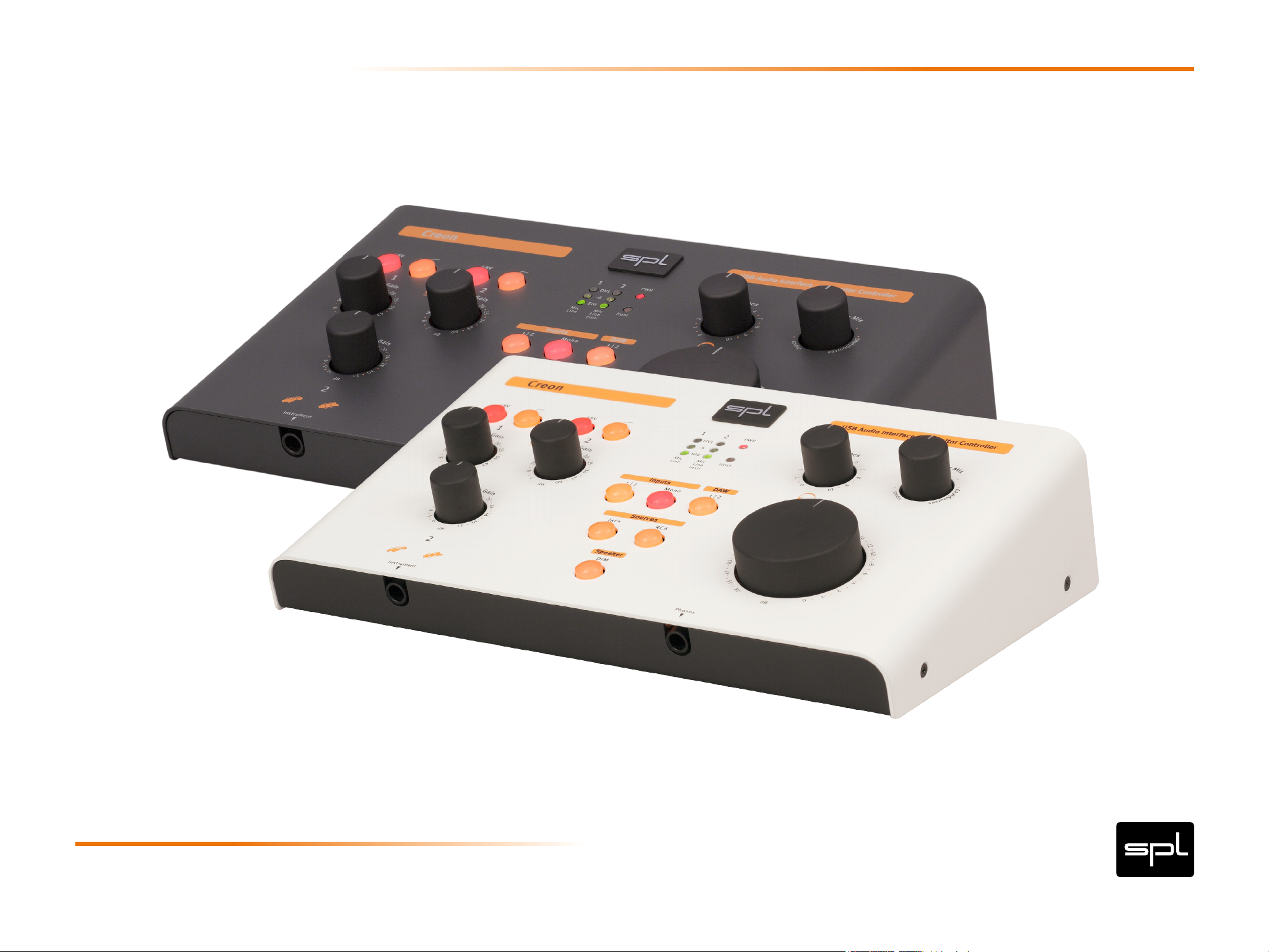
Creon (Black: Model 1410, White: Model 1412)
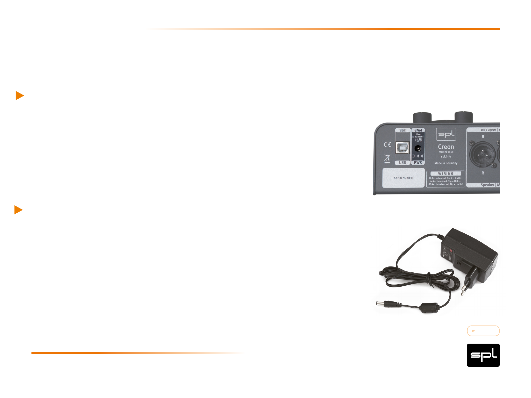
12 V power supply
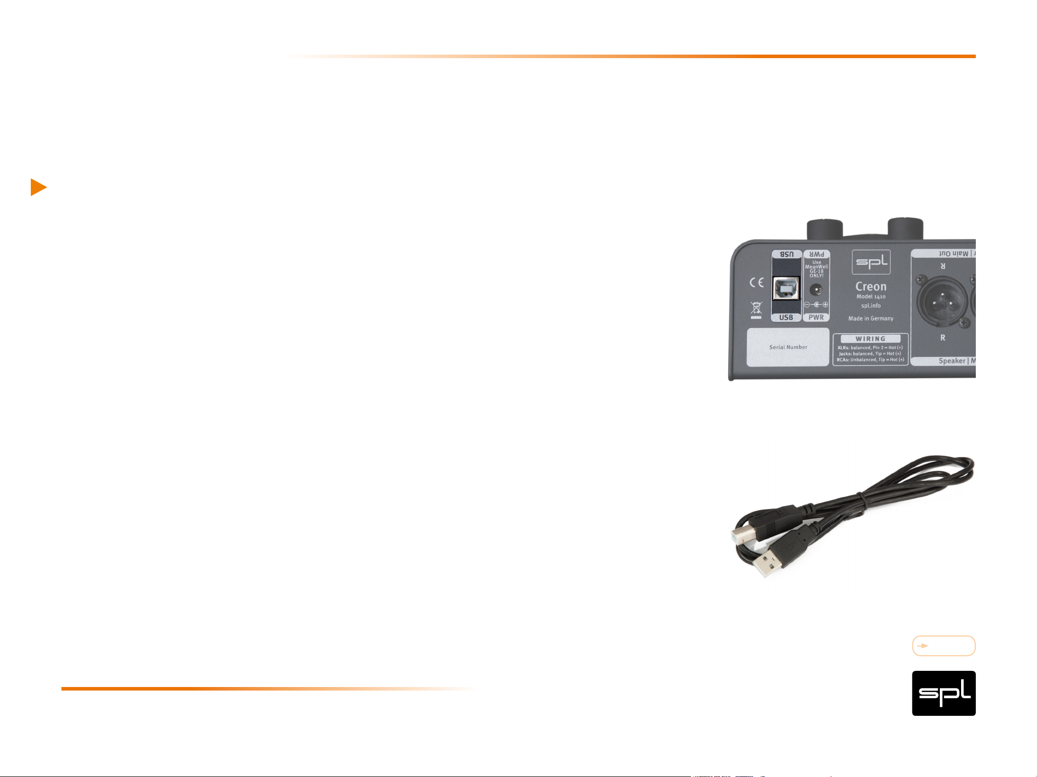
USB cabel
Product Overview
Scope of Delivery
Measurement & Weight
Height x Width x Depth in mm: 67 x260 x 175 (2.64x10.2x6.9 inch)
Weight: 2,7 kg (without external power supply)
Please keep the original packaging. In case of a service procedure the original packaging ensures a
safe transport. It also serves as a safe packaging for your own transports if you do not use special
transportation cases.
Content
5Creon
Page 6

Welcome
and thank you for purchasing the Creon. It combines a high-performance USB audio
interface with high-quality preamps and a separate, fully-featured analog monitor controller. You can play and play back, record and convert, control and listen with one
single device. So all you essentially need for a truly professional recording setup is the
Creon and a DAW.
Introduction
With and without DAW
Creon is designed to operate with your Digital Audio Workstation. But you can also do
a lot with it as a stand-alone device: plug in an instrument and play. Connect a microphone and sing along. Mix your own monitor signal with playback or guide tracks from
any source. What you are playing is not bad? Turn on the DAW and record it.
Content
6Creon
Page 7
Hardware
USB 2-Audio-System
High-performance, 32 bit microcontroller
24 bit audio processing
2 input and 2 output channels
Sample rates (kHz): 44.1, 48, 88.2, 96, 176.4 or 192
Fixed master clock for lowest jitter
USB Interface
True 1:1 audio, no sample rate conversion or clock recovery
Software
Windows XP/7/8/10 (32 & 64 Bit), Mac OS X 10.6 or higher, iOS 6 or higher
Multi-application mode, simultaneous ASIO and/or WDM playback
Low-latency driver
Driver feedback synchronization to hardware clock
ASIO control panel for Windows
USB Audio Class 2.0 compliance (asynchronous mode)
Firmware updates via USB.
Info:
Download the latest drivers and rmware from
www.creon.spl.info.
Mac OS: There is no need to install drivers for
the Creon!
Content
7Creon
Page 8

AD Conversion
AD/DA Conversion
Dynamic Range
44.1 / 48 kHz: 128 dB
88.2 / 96 kHz: 123 dB
SNR:
44.1 / 48 kHz: -113 dB
88.2 / 96 kHz: -110 dB
DA Conversion
Dynamic Range
44.1 / 48 kHz: 124 dB
THD+N ratio at 1 kHz (-1 dBFS):
44.1 / 48 kHz: 0,002%
88.2 / 96 kHz: 0,0025%
0 dBFS = +15 dBu
Sample Rates (kHz): 44.1, 48 , 88.2, 96, 176.4, 192
88.2 / 96 kHz: 122 dB
SNR:
44.1 / 48 kHz: -109 dB
88.2 / 96 kHz: -107 dB
Content
8Creon
Page 9

Placement
Place the unit on a leveled and stable surface or mount it in a dedicated rack frame.
The unit’s enclosure is EMC-safe and effectively shielded against HF interference.
Nonetheless, you should carefully consider where you place the unit to avoid electrical
disturbances. It should be positioned so that you can easily reach it, read the meters
and status LED‘s well, but there are other considerations as well. Try not to place it
near heat sources or in direct sunlight, and avoid exposure to vibrations, dust, heat,
cold or moisture.
Hook Up
Additional safety instructions on page 41.
For more information on how to calibrate your monitoring system please refer to pages 38 and 39.
Content
9Creon
Page 10
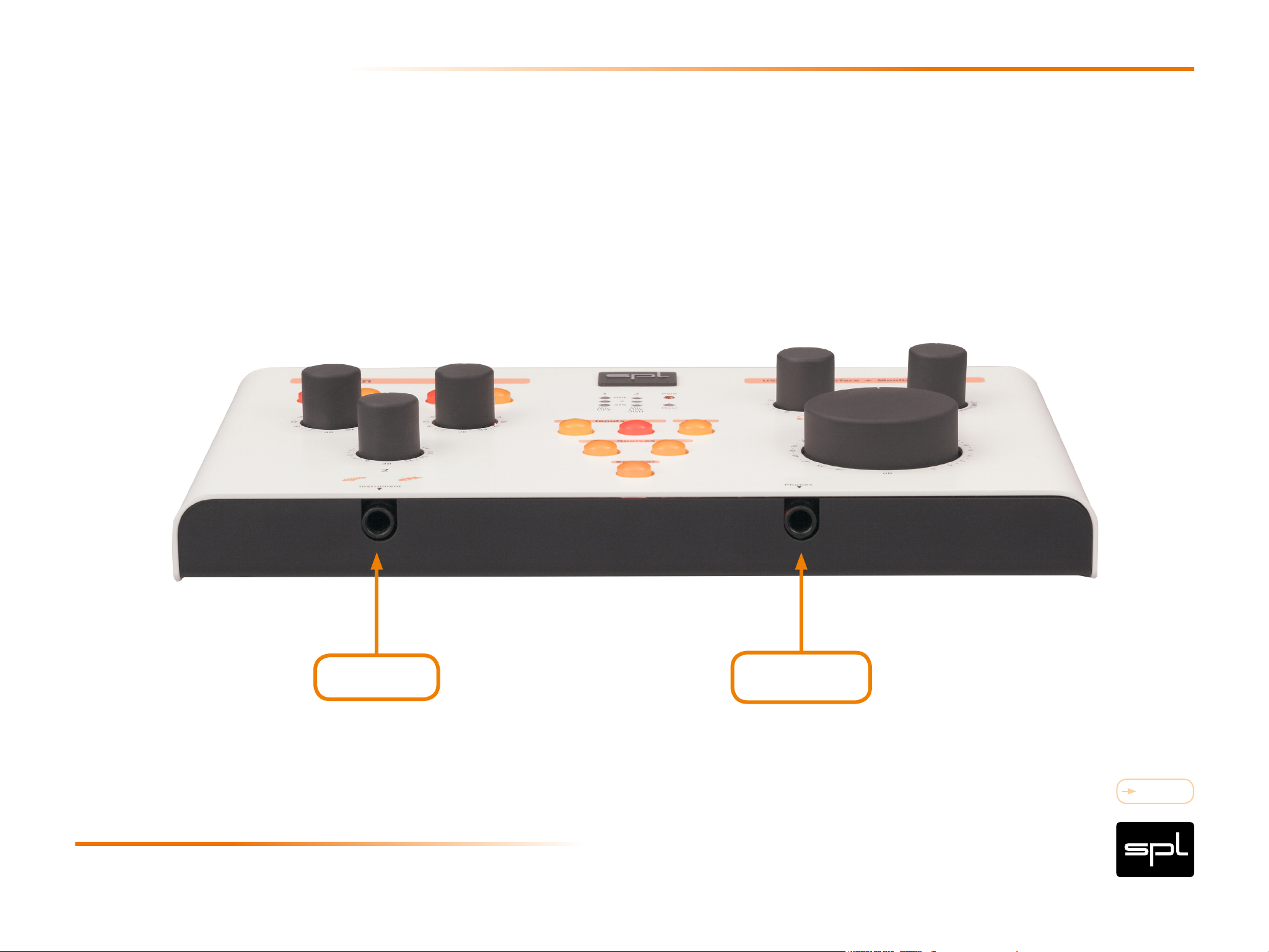
Front Panel: Wiring Diagram
Instrument Headphones
Content
10Creon
Page 11
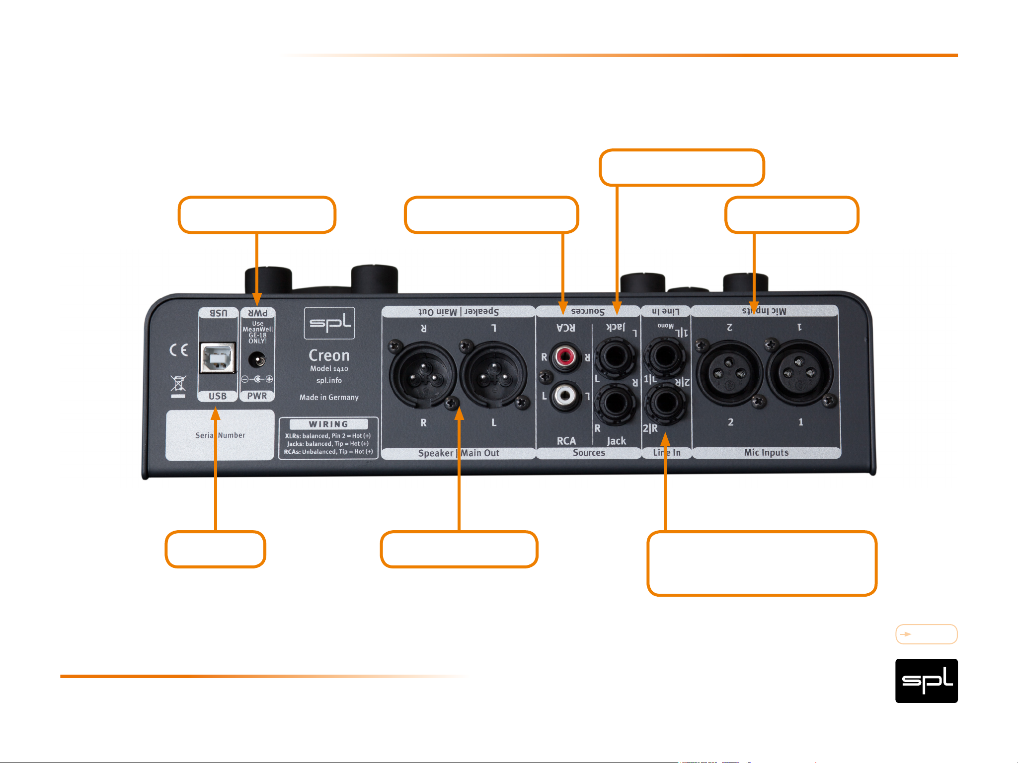
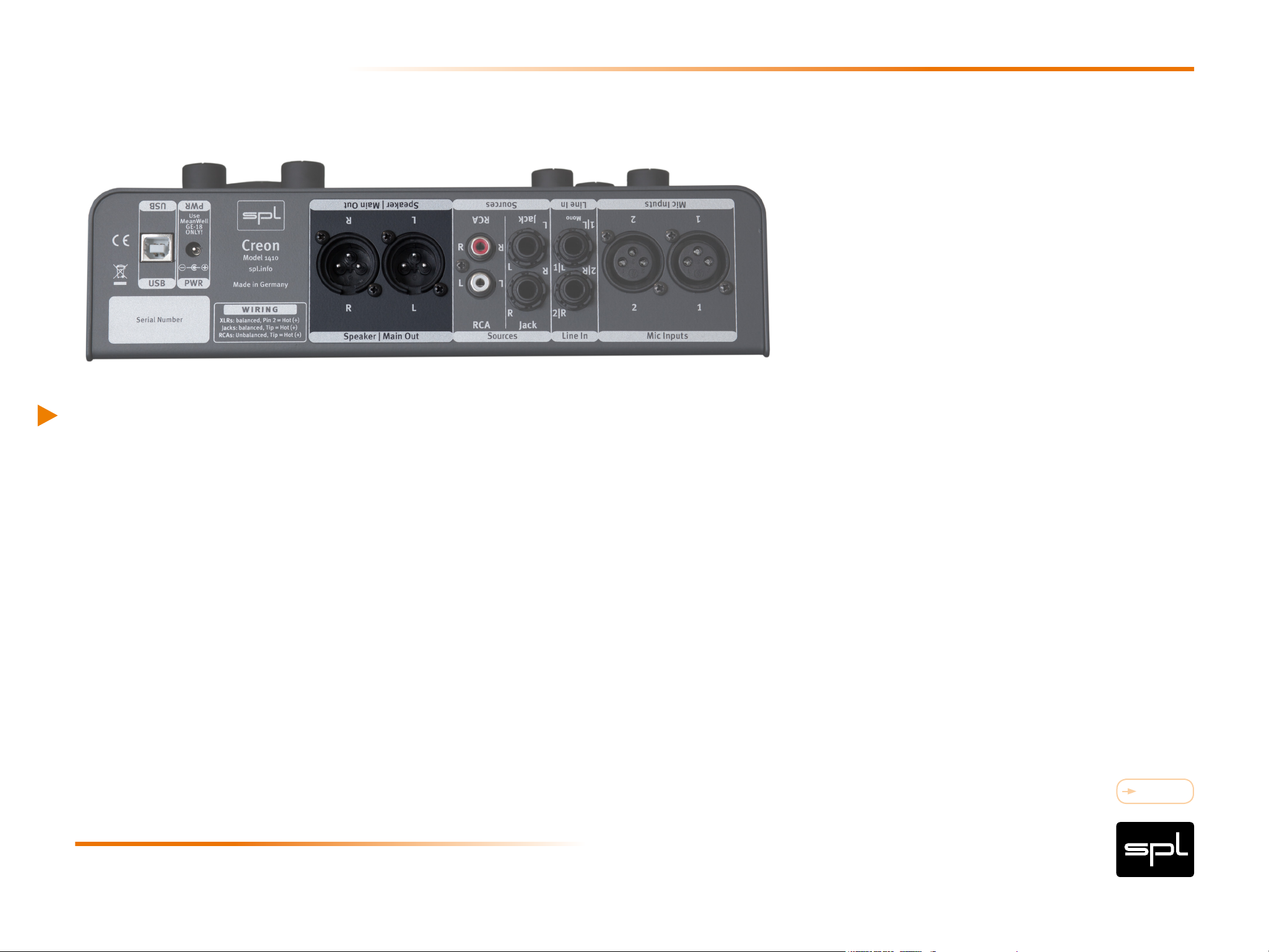
Rear Panel: Wiring Diagram
Balanced Source
Power Supply
e.g. CD-Player analog
Microphone
DAW Speaker Set
e.g. Keyboard, Synthesizer,
Preamplifier/Channel Strip
Content
11Creon
Page 12
USB
Connect here your computer. Alternatively you can connect an iPad or iPhone with the
original Apple camera adapter. The USB port complies with the Hi-Speed USB 2.0 specification with a data transfer rate of 480 MBit/s, and is Apple Class 2 compliant as
well.
USB 3 is backward compatible with USB 2, which means that the Creon can also be
connected to any USB 3 port. The Hi-Speed USB 2 specification is enough to provide
the Creon with the necessary data throughput. We decided to use the USB 2 interface
Connections
due to the reliability of the drivers..
The package includes an appropriate USB cable.
In case you use a different cable, make sure it complies to the Hi-Speed USB 2 specification. It recommends a maximum length of five meters. We recommend to keep the
cables as short as possible, remember: the shorter, the better. For cable runs extending over five meters, you could use a hub or a line extender, in which case you should
get the advice of an expert.
Content
12Creon
Page 13
Power Connection
Connect the DC connector of the external power supply to the rear DC IN socket of the
Creon. Plug the power supply to a wall power socket.
The PSU comes with an appropriate mains adapter for the country where the Creon is
bought. You can find detailed information in the separate sheet along with the safety
instructions.
Connections
Power Supply
External Power Supply: Mean Well GE-18
Input 100–240V AC/50–60 Hz; Output 12V DC/1,5A
Internal Power Supplies
Audio: +/- 17 V, Digital + 5 V and + 3,3 V
Power Consumption: 16,8 Watt
Content
13Creon
Page 14
Signal Connections
Remove the DC plug from the Creon and make sure all connected gear is switched off before
tinkering with the cables.
We recommend to connect the Creon and all other audio devices in the same network to
a high-quality and appropriately rated multi-outlet power strip from where you can cut-off
and restore the power supply.
In any case, the connection of the audio network to a power outlet is the general recommendation, in order to avoid ground loops and other similar noises that could arise due to
Connections
connection points having different potentials.
Content
14Creon
Page 15
Speaker Outputs (Speaker | Main Out)
You can connect one set of active stereo speakers or a power amplifier to Creon.
Connections
Specications:
XLR balanced
(Pin 1=Ground, Pin 2=cold, Pin 3=hot)
Output impedance 75 Ohm unbalanced, 150 Ohm balanced
Maximum output level +22.5 dBu.
Content
15Creon
Page 16

Connections
Sources 1 and 2
You have two stereo source inputs with different connectors at your disposal: Source
input 1 via two mono jacks (balanced), Source input 2 via two RCA connectors.
This means you can connect two audio devices as playback sources, be it a CD or MP3
player, a tape machine or even a smartphone.
Typical applications include the use of reference tracks to do A/B comparisons or playing an instrument on top of a song while listening to it — everything without the need
to connect the Creon to a computer.
IMPORTANT:
The source inputs are conventional playback
channels. Their signal cannot be recorded with
a DAW.
Content
16Creon
Page 17

Source 1: Jack
Connect here signal sources with balanced connections, for example, a DA converter.
Connections
If you only connect the left channel, the signal is automatically placed as mono in the
monitoring path (in the center of the stereo image).
Specications:
1/4“ jack, balanced
(Sleeve=Ground, Tip=hot, Ring=cold
Input impedance: 10kOhm unbalanced, 20kOhm balanced
Maximum input level +22.5 dBu.
Frequency Response: 10Hz - ›200kHz
Noise: -95 dBu (unweighted, unity gain, input termination 600 Ohm)
Common Mode Rejection ratio: ‹ -60 dBu
THD+N Ratio: 0,002% (at 1kHz, unity gain, input termination 600 Ohm)
Content
17Creon
Page 18

Source 2: RCA
RCA connectors are ideal for any type of consumer devices with unbalanced connec-
Connections
tions, for example CD/DVD/BluRay player, AV receiver, Sat receiver, cable receiver, etc.
Input level is boosted to pro level (0 dBu) by default.
Specications:
RCA connector
Input impedance: 10kOhm
Maximum input level +22.5 dBu
Frequency Response: 10 Hz - ›200 kHz
Noise: -90 dBu (unweighted, unity gain, input termination 600 Ohm)
Noise: -85 dBu (unweighted, -10dBV, input termination 600 Ohm)
THD+N Ratio: 0,003 % (at 1 kHz unity gain, input termination 600 Ohm)
THD+N Ratio: 0,003 % (at 1 kHz, -10 dBV, input termination 600 Ohm)
Content
18Creon
Page 19

Input Selection:
Connections
Microphone-, Instrument- und Line Inputs
Taking into account both microphone inputs, the instrument and four line inputs, you
have five analog inputs at your disposal. Two of the five inputs can be used simultaneously for recording purposes.
The selection is defined by the assignment of the corresponding inputs. This has the
added advantage that the channel configuration can be directly and intuitively made
out by the assignment of the connections, plus there is almost no need for switching.
The input selection follows this provision:
Line 1|2 has preference over Mic Input 1|2
Instrument input has preference over Mic input 2 and Line input 2
IMPORTANT:
To record microphone signals, Line 1 and/
or Line 2, Instrument ought to be free. If you
cannot hear a microphone signal, check
whether Line 1, Line 2 or Instrument input are
free or not.
Content
19Creon
Page 20

Mic Inputs
You can connect dynamic, condenser, tube, and ribbon microphones to the mic inputs.
Use the Phantom switch to provide phantom power to the microphones that require it.
For more information, read the „48 V“ section on page 28.
Connections
XLR Sockets
The image below shows the XLR connectors
pinout. They are balanced and have three conductors or wires. Conductor 2 (Pin 2) corresponds to the (+) or hot Signal. The diagram also
shows how to wire the balanced XLR connections if unbalanced connections are required,
for example to RCA or TS inputs and outputs
Specications: XLR connectors
Input impedance 10 kOhm
Maximum input level +14.5 dBu (Gain knob hard left).
Frequency Response: 10 Hz - ›200 kHz
Noise: -90 dBu (unweighted, 30dB gain, input termination 150 Ohm)
Equivalent Input Noise: -128 dBu
Common Mode Rejection Ratio: ‹ -70 dBu
THD+N Ratio: 0,003 % (at 1 kHz, 30 dB gain, input termination 150 Ohm)
Input
balanced
2
1
3
unbalanced
2
1
3
1= GND
2=hot (+)
3=cold (-)
balanced
2
1
3
20Creon
Output
unbalanced
2
1
3
Content
Page 21

Line Inputs
You can connect and record two line signals. Besides keyboards and synths you can
Connections
connect here other external sources like preamps or channel strips. Both balanced line
inputs are routed 1:1 to the converter and monitoring section. Level adjustment is not
possible.
Specications:
1/4“ stereo jacks, unbalanced
Input impedance 10 kOhm, balanced input impedance 20kOhm
Maximum input level +22.5 dBu
Frequency Response: 10 Hz - >200 kHz
Noise: -95 dBu (unweighted, unity gain, input termination 600 Ohm)
Common Mode Rejection ratio: < -60 dBu
THD+N Ratio: 0,002 % (at1 kHz unity gain, input termination 600 Ohm)
Ring
Content
Tip Sleeve
21Creon
Page 22

Instrument Input
Connections
The Instrument input is on the front panel so it can be reached directly. It supports high
levels to allow the connection of active or passive instruments, and it has a corresponding high impedance. Active instruments already feature a preamp circuit, passive do
not (only pickups). Connection examples: electric guitars and basses, acoustic guitars
with pickups, etc.
Specications:
1/4“ mono jack, unbalanced
(Sleeve=Ground, Tip=hot/Signal)
Input impedance 1.1 MOhm, maximum input level +24.0 dBu
Frequency Response: 10Hz - >200kHz
Noise): -85 dBu (unweighted, unity gain, input termination 100 kOhm
THD+N Ratio: 0,005 % (at 1kHz unity gain, input termination 100 kOhm)
IMPORTANT:
Low impedance line signals (D/A converter,
sampler, synthesizer, etc.) ought to be con-
nected to the line inputs on the rear panel.
Content
22Creon
Page 23

Connections
Phones
Use the Phones jack on the front panel to connect your headphones. You can connect
all types of headphones with impedances from 20 to 600 Ohm. This wide range entails
big volume differences between low- and high-impedance headphones. In order to
keep under control low impedance headphones, we set a comparatively high impedance of 33 Ohms at the output.
Specications:
1/4“ stereo jacks
(Sleeve=Ground, Tip=left channel, Ring=right channel)
Output impedance 33 Ohm
Frequency Response: 10Hz - >200kHz
IMPORTANT:
When connecting them, make sure that the plug
is completely in and that is rmly attached.
Power at 0 dBu:
47 Ohm load: 13 mW
300 Ohm load: 1,7 mW
600 Ohm load: 1,0 mW
Power max.:
47 Ohm load: 670 mW
300 Ohm load: 265 mW
600 Ohm load: 150 mW
THD+N Ratio (at 1 kHz, Power at 0dBu)
47 Ohm: 0,0026 %
300 & 600 Ohm: 0,002 %
Content
23Creon
Page 24

Important Recommendations
Always reduce the volume before you connect or disconnect your headphones or head-
Connections
phone preamp, for example to change headphones. This way you will avoid loud crackling noises reaching your ears. Plus, it will also spare you unexpected surprises whe-
never the new headphones you connect have a lower impedance or a higher efciency,
which will make them sound louder when connected to the Creon and keeping the
same volume setting.
Never connect mono plugs to the stereo jacks on the front panel. Otherwise you can
cause a short circuit that will damage the amplier! Headphone cables always have
stereo plugs.
Content
24Creon
Page 25

Unbalanced Connections
XLR/Stereo Jack to Mono Plug/RCA
Connections
Unbalanced connections are also possible without the need of an adapter. It is important to verify the polarity of the three balanced wires. The image shows the pinout
of the XLR connectors, as well as the correct polarity for connections with unbalanced cables, whereby Pin 1 and 3 ought to be connected (for the stereo plug: ring and
ground). We recommend the use of specially manufactured 1/4“ stereo jack/XLR to
1/4“ mono plug/RCA cables to avoid the use of adapters. Such cables can be found in
specialized shops. The pinout diagram will help the specialist dealer make sure he provides you with correctly configured cables.
Input
balanced
2
1
3
unbalanced
2
1
3
1= GND
2=hot (+)
3=cold (-)
balanced
1
3
2
Output
unbalanced
2
1
3
Content
25Creon
Page 26

Control Elements
Content
26Creon
Page 27

Mic Gain
The Creon features two identical microphone preamps. The preamps are discrete,
which means they use single transistors instead of ICs. This allows the preamp to be
perfectly optimized for its task — such efforts are usually taken only in the production
of high-end preamps.
Use the Mic Gain control to adjust the microphone preamp level. The adjustable
volume range spans from +3 to +60dB. To achieve the best recording level, the -6dB
LED should flash from time to time: you have enough headroom left. If the LED remains
always on, it means that the level is at the brink of overloading — in such cases, you
Control Elements
should reduce the Mic Gain value.
The OVL LED indicates the Creon‘s converter is overloading, which should be strictly
avoided.
IMPORTANT:
Line 1|2 has preference over Mic Input 1|2
Instrument input has preference over Mic input 2 and Line input 2
To record microphone signals, Line 1 and/
or Line 2, Instrument ought to be free.
If you cannot hear a microphone signal,
check whether Line 1, Line 2 or Instrument
input are free or not.
Content
27Creon
Page 28

48 V
Use the 48V switch above the Mic Gain knob to activate the 48 Volt phantom power
to supply condenser microphones with an integrated preamp. To work correctly such
microphones require a clean, noiseless voltage, which the Creon can provide.
IMPORTANT:
First connect the microphone to the Creon and then engage the phantom power. Now
you can start to work. Once you are done, disengage the phantom power first. Wait at
Control Elements
least ten seconds after disengaging the 48 V phantom power, before you disconnect
the microphone from the Creon, to allow for complete discharging — otherwise you
could damage the Creon‘s input stages.
VERY IMPORTANT:
All condenser microphones with a balanced, oating output, as well as ribbon
microphones, can be used with phantom
power. A microphone with an unbalanced
output should only be used without phantom power! We recommend you to disengage the phantom power for all types of
microphones except condenser micropho-
nes .
Content
28Creon
Page 29

High-Pass Filter
The high-pass filter passes high-frequency signals but filters out impact noise, rumble
and other unwanted noises below 75 Hz. This first order filter has a 6dB/octave slope,
which means it is soft and goes unnoticed acoustically speaking.
Besides impact noise, other unwanted noises include the ones produced when handling the microphone.
Application examples:
Control Elements
Stage miking, speech recordings, vocals and high-pitched instruments where you are
sure that you will not need to record lower-pitched neighboring instruments.
Another aspect you should consider: low frequencies require a lot of energy during
conversion, which is another argument for engaging the high-pass filter when the
recording allows for it.
Content
29Creon
Page 30

Instr Gain
The Creon also includes an instrument preamp. Use the Instr Gain control to adjust
the instrument preamp level in steps. The adjustable volume range spans from -6 to
+31dB. The possibility to reduce the level -6dB allows for the direct connection of electric bass guitars. To achieve the best recording level, the -6dB LED should flash from
time to time: you have enough headroom left. If the LED remains always on, it means
that the level is at the brink of overloading — in such cases, you should reduce the Instr
Gain value. The OVL LED indicates the Creon‘s converter is overloading, which should
be strictly avoided.
Control Elements
IMPORTANT:
Instrument input has preference over Mic input 2 and Line input 2
Content
30Creon
Page 31

LED Indicators
The central LED display panel provides information about the operating status and
also helps you adjust better microphone and instrument signals.
Level Adjustment with two LED sets
Two traffic-light-like LED sets indicate the level of the four recording channels. Every
set of LEDs is numbered: set 1 correspond to mic preamp 1 and set 2 correspond to
mic preamp 2 and the instrument preamp.
Control Elements
Each LED set is identical to the others:
The OVL LED lights red to indicate the Creon‘s converter is being overloaded
The -6 (dB fs) LED lights yellow. An optimally adjusted level makes it flicker on and off
from time to time
The SIG LED lights green and indicates the presence of a signal
OVL > +15 dBu ( Host LED on)
> +20 dBu ( Host LED off)
-6 > +9 dBu
SIG > -20 dBu
Content
31Creon
Page 32

Special note regarding the OVL LED:
this LED is directly connected to the converter and thus indicates the overloading of
the converter. Make sure it never lights during a recording, otherwise you risk ending
up with a useless take due to the presence of audible distortion. As a safety measure,
the OVL LED remains lit for around a second.
Status LEDs
Control Elements
The PWR LED indicates the power supply of the unit.
The HOST LED indicates that a host computer has been detected at the USB port and
the connection has been correctly established.
Note:
When used standalone, without DAW or iPad connected to the USB port, the digital
section is not initialized. And since the OVL LED is controlled directly by the converter,
if not initialized, the OVL LED is inactive.
Content
32Creon
Page 33

Analog Inputs
The Creon allows the simultaneous recording of two analog inputs.
Switch 1|2 engaged: you hear Mic or Line inputs 1 and 2.
When recording a mono vocal track it makes sense to hear it in the center of the stereo
image, so you should engage the Mono switch as well.
DAW Returns
Control Elements
The Creon has two DA converters that allow you to monitor a stereo signal (two chan-
nels) from the DAW.
Switch 1|2 engaged: you hear the Mix from DAW outputs 1/2.
Content
33Creon
Page 34

Sources
As a true monitor controller, you can also use the Creon as a preamp for two stereo
sources. Use the two switches under Sources to manage the two source inputs, which
are named after their connector format. For more information on the connectors refer
to „Sources 1 and 2“ on page 16.
JACK = balanced 1/4“ input (for a professional CD player or a converter, for example)
RCA= unbalanced RCA input (Hi-Fi CD player, AV receiver or similar)
Control Elements
Note: the level of both unbalanced inputs is automatically converted to professional
level in order for them to be directly comparable according to the Creon‘s standard
level.
Speaker DIM
The DIM switch reduces the monitoring level -20dB.
Content
34Creon
Page 35

Monitor Mix
With the Monitor Mix control you create a monitor mix fast and easily. No need to fi
ddle with gain controls or faders, just blend between the Inputs (mic, line, instrument)
and the DAW/Sources.
The analog monitoring of all analog inputs and sources is absolutely latency-free, it is
as real-time as it gets.
Control Elements
In the center position (1:1), the volume of the analog inputs (mic, line, instrument) and
DAW returns and sources is balanced. When set hard left, you can only hear the analog
inputs (mic, line, instrument). Hard right you can only hear the DAW returns and sources through your monitoring system.
Content
35Creon
Page 36

Phones
The Creon features a powerful headphone amplier. Use the Phones volume control to
adjust the level of the headphones signal.
Headphones volume adjustment is also independent from that of the loudspeakers.
The outputs and gain are designed for headphones with impedances from 20-600
Ohms. For more details regarding the connection of headphones, refer to „Headphone
Outputs“ on page 23.
Control Elements
Optimal Potentiometer Control Range
The control range of the headphone amplifiers is very wide: it allows you to listen to
very high level signals with 30 Ohm headphones, as well as to detect the faintest
details in quiet passages with 600 Ohm headphones. To achieve such a wide range,
and due to component characteristics, a constant taper during the beginning of the
travel of the potentiometer cannot be guaranteed. A reduction of the overall volume
would also lower the tolerance in this initial range, but at the price of wasting power
margin. Thus, we recommend you to adjust the level above the „1“ mark to achieve the
best results.
Content
36Creon
Page 37

Volume
Use the Volume potentiometer to adjust the volume of both channels of the
Speaker | Main Out outputs on the rear panel. The high-grade potentiometer regulates
the audio signal directly to avoid any coloration/distortion typical of VCAs and DCAs,
which require higher inter-channel tolerances and have a tendency towards higher distortion figures. The Volume control uses a relative dB scale referenced to the input
level. When set to the 0dB mark the input level is „as is“ (the amplification factor is 1
or unity gain).
The signal can be attenuated up to -78dB.
Control Elements
If the signal can still be heard when hard left, do not worry: the potentiometer is not a
switch. This was a conscious decision we made to be able to offer you an amplification
possibility too. Power off the source when you want to mute it.
Recommendation: Calibrate the whole monitoring system (read the following section)
so that the control range in use is always between eight and two o‘clock of the travel.
This is the range where the potentiometer works best, which guarantees a good and
noiseless level matching for the monitoring system.
Content
37Creon
Page 38

Calibration of the Monitoring System
Calibration of the Monitoring System (Part 1)
The input signal level of the Creon and the input sensitivity of the power amps or
active speakers should be matched to ensure a proper overall gain. An inappropriate
matching results, for example, in an extremely high monitoring level with a fairly low
volume setting (at 9 o‘clock). Likewise, settings above two o‘clock should sound really
loud, otherwise it is indicative of a matching problem.
During calibration it can get very loud and annoying, so don‘t forget to wear ear
protection.
For calibration we recommend using a SPL Meter (where SPL stands for „Sound
Pressure Level“). Place the measuring microphone at the listening position and playback pink noise from a generator calibrated to 0dBu. Each measurement should be
done with one channel (and loudspeaker) at a time. 83dB SPL at the listening position
is a good and very common reference value.
Content
38Creon
Page 39

Calibration of the Monitoring System
Calibration of the Monitoring System (Part 2)
Adjust the volume control until the SPL meter reaches 83dB with pink noise.
Ideally, 83dB SPL should be reached when the volume control is near the 12 o‘clock
mark.
Write down the exact value for 83dB SPL at the listening position. If it only reaches
83dB SPL above two o‘clock, increase the power amps‘ or active loudspeakers‘ input
sensitivity (higher dB value).
Conversely, you should decrease the power amps‘ or active loudspeakers‘ input sensitivity (lower dB value) when it indicates 83dB SPL before reaching the 12 o‘clock mark.
Content
39Creon
Page 40

Exclamation mark within a triangle
An exclamation mark within a triangle is intended to make you aware of important operational advice and/or warnings that must be followed. Be especially attentive to these
and always follow the advice they give.
Lightning symbol within a triangle
In this Manual a lightning symbol within a triangle warns you about the potential for
dangerous electrical shocks – wich can also occur even after the device has been dis-
Symbols
connected from a power source.
Symbol of a lamp
The symbol of a lamp directs your attention to explanations of important functions or
applications.
Content
40Creon
Page 41

Connections
Only use the connections as described. Other connections can lead to health risks and
damage the equipment.
Water and humidity
Do not use this device anywhere near water (for example in a bathroom, a damp cellar,
near swimming pools, or similar environments). Otherwise your are dealing with an
extremely high risk of fatal electrical shocks!
Security Advices
Insertion of objects or fluids
Be careful to not insert any object into any of the chassis openings. You can otherwise
easily come into contact with dangerous voltage or cause a damaging short circuit.
Never allow any fluids to be spilled or sprayed on the device. Such actions can lead to
dangerous electrical shocks or fire!
Content
41Creon
Page 42

Air ventilation
Chassis openings offer ventilation and serve to protect the device from overheating.
Never cover or otherwise close off these openings. Never place the device on a soft
surface (carpet, sofa, etc.)..
Electrical power
Operate the device only from power sources that can provide proper power. When in
doubt about a source, contact your dealer or a professional electrician. To be certain
Security Advices
you have isolated the device, disconnect all power and signal connections. Make sure
that the power supply plug is always accessible. When not using the device for a longer
period, make sure to unplug it from your wall power socket.
Opening the unit
Simply put: DON‘T, if you are not a certified SPL technician or engineer. Really: Do not
open the device housing, as there is great risk you will damage the device, or – even
after being disconnected – you may receive a dangerous electrical shock!
Content
42Creon
Page 43

Power connection overloads
Avoid any kind of overload in connections to wall sockets, extension or splitter power
cords, or signal inputs. Always keep manufacturer warnings and instructions in mind.
Overloads create fire hazards and risk of dangerous shocks!.
Lightning
Before thunderstorms or other severe weather, disconnect the device from wall
power; do not do this during a storm in order to avoid life threatening lightning strikes.
Security Advices
Similarly, before any severe weather, disconnect all the power connections of other
devices and antenna and phone/network cables which may be interconnected so that
no lightning damage or overload results from such secondary connections.
Content
43Creon
Page 44

Controls and switches
Operate the controls and switches only as described in the manual. Incorrect adjustments outside safe parameters can lead to damage and unnecessary repair costs.
Never use the switches or level controls to effect excessive or extreme changes.
Repairs
Unplug the unit from all power and signal connections and immediately contact a
qualified technician when you think repairs are needed – or when moisture or foreign
Security Advices
objects may accidentally have reached inside the housing, or in cases when the device
may have fallen and shows any sign of having been damaged. This also applies to any
situation in which the unit has not been subjected to any of these unusual circumstances but still is not functioning normally or its performance is substantially altered. In
cases of damage to the power supply and cord, first consider.
Content
44Creon
Page 45

Replacement/substitute parts
Be sure that any service technician uses original replacement parts or those with identical specifications as the originals. Incorrectly substituted parts can lead to fire, electrical shock or other dangers, including further equipment damage.
Safety inspection
Be sure always to ask a service technician to conduct a thorough safety check and
ensure that the state of the repaired device is in all respects up to factory standards.
Security Advices
Cleaning
Do not use any solvents, as these can damage the chassis finish. Use a clean, dry cloth
(if necessary, with an acid-free cleaning oil). Disconnect the device from your power
source before cleaning.
Content
45Creon
Page 46

Declaration of CE Conformity
The construction of this unit is in compliance with the standards and regulations of the
European Community.
Notes on Environmental Protection
At the end of its operating life, this product must not be disposed of with regular
household waste but must be returned to a collection point for the recycling of electrical and electronic equipment.
Creon
The wheelie bin symbol on the product, user‘s manual and packaging indicates that.
The materials can be reused in accordance with their markings.
Through reuse, recycling of raw materials, or other forms of recycling of old products,
you are making an important contribution to the protection of our environment.
Your local administrative office can advise you of the responsible waste disposal point.
WEEE Registration: 973 349 88
Content
46Creon
Page 47

Contact
SPL electronics GmbH
Sohlweg 80
41372 Niederkrüchten
Fon (0 21 63) 98 34 0
Fax (0 21 63) 98 34 20
E-Mail: info@spl.info
Creon
Or follow us on our Blog, Facebook, Twitter and YouTube:
Website & Blog: spl.info
Videos: youtube.spl.info
Twitter: twitter.spl.info
Facebook: facebook.spl.info
Content
47Creon
 Loading...