

Page 1
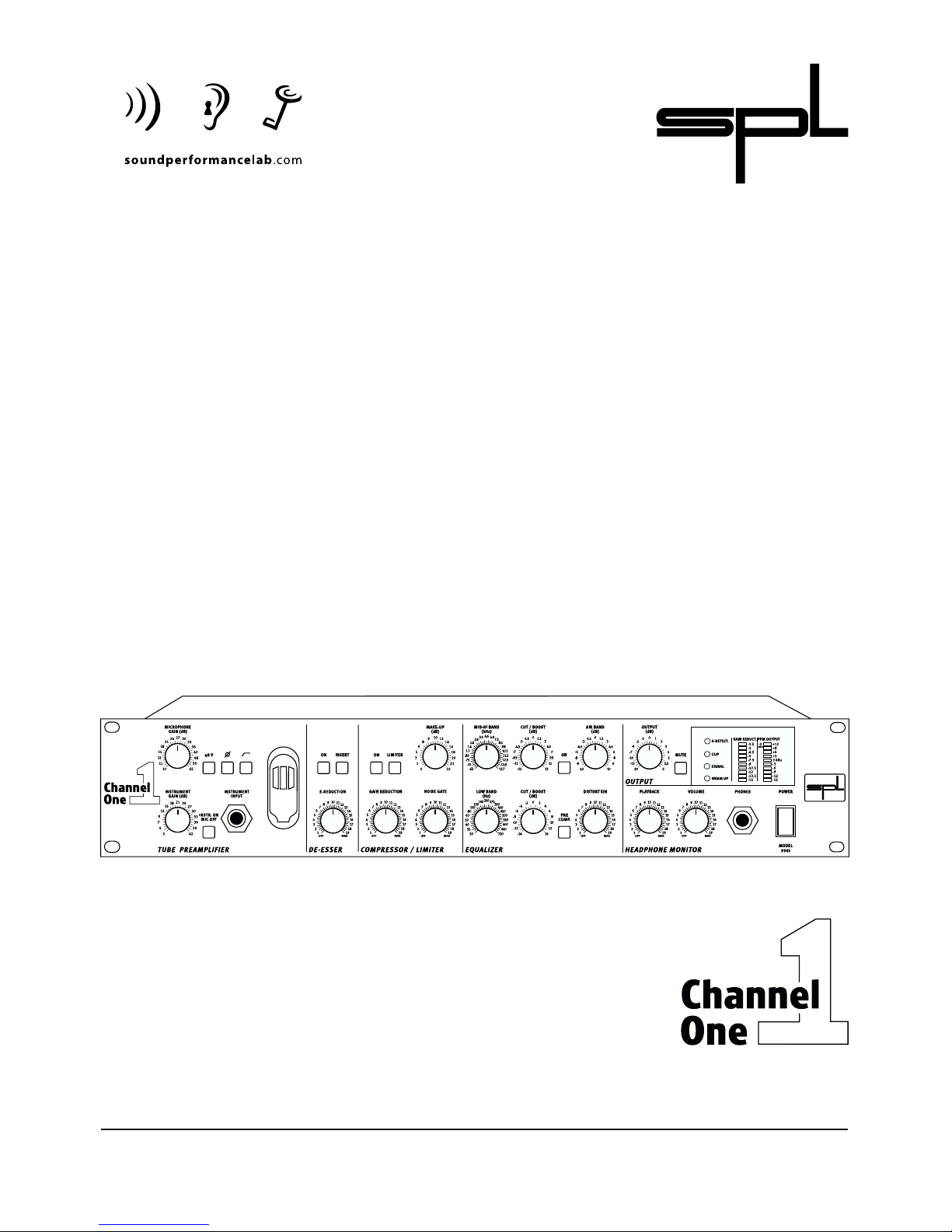
Model 9945
Manual
Channel Strip
Page 2

2
Manual Channel One
Model 9945
Version 1.1 - 5/2000
R & D:Ruben Tilgner
The information in this document has been carefully verified and is
assumed to be correct. However Sound Performance Lab (SPL) reserves the
right to modify the product described in this manual at any time. Changes
without notice.This document is the property of SPL and may not be copied
or reproduced in any manner,in part or full without the authorisation of SPL.
Limitations of Liability:
In no event will SPL be liable for any damages, including loss of data, lost
profits, cost of cover or other special, incidental, consequential or indirect
damages arising from the use of the unit, however caused and on any theory
of liability.This limitation will apply even if SPL or an authorised dealer has
been advised of the possibility of such damage.
Sound Performance Lab
P.O.Box 12 27
D- 41368 Niederkruechten, Germany
Phone +49 - 21 63 / 98 34-0
Fax +49 - 21 63 / 98 34-20
eMail: info@soundperformancelab.com
www.soundperformancelab.com
© 2000 SPL electronics GnbH. All Rights Reserved. Subject to change without notice.
Page 3

3
Contents
Introduction ................................................................................................................... 4
Principles ......................................................................................................................... 4
Hookup ............................................................................................................................. 5
Connections:
Rear front / Wiring .......................................................................................................... 6
General advises / Connectors ..................................................................................... 7
Operation:
• Preamplifier
Microphone Gain, 48 Volt phantom power, phase reverse,high pass ........... 9
Highpass,Instrument Gain,About levelling,
Instr./Line On - MicOff,Instr. Input ............................................................................10
• De-Esser
On,S-Reduction,Technical Information regarding De-Esser ............................11
• Insert
Insert ..................................................................................................................................12
• Compressor/Limiter
On .......................................................................................................................................12
Limit,Gain Reduction, Noise Gate ............................................................................13
Make Up,Technical Information regarding the Compressor/Limiter .............14
• Equalizer
On,Pre Comp.,Air Band ...............................................................................................15
Mid-Hi Band,Cut/Boost (Mid-Hi),Low Band,Cut/Boost (Low) .........................16
Tip for frequency setting,Distortion ........................................................................17
• Output
Output,Mute ...................................................................................................................18
• Headphone Monitor
Playback,Volume,Phones ...........................................................................................19
• Displays
S-Detect., Clip, Signal,Warm Up .................................................................................20
Gain Reduction, PPM-Output .....................................................................................21
Power supply .................................................................................................................21
Specifications ...............................................................................................................22
Block Diagram ..............................................................................................................23
Measurements ..............................................................................................................24
Warranty ..........................................................................................................................26
Copy Master ...................................................................................................................27
Notes .................................................................................................................................28
Page 4

4
Introduction
SPL is mainly known for the development of highly specialized audio-tools.
Our philosophy, ”one product for one task”,is aimed at fast and simple operation in conjunction with high processing quality, to ensure highest musical
performance.
With Channel One SPL have produced a complete channel strip which for
the greater part is based on the processing concepts already successfully
realized in other products. The very complex task of a channel strip profits
particularly from the innovative techniques that have always allowed the
operation of SPL equipment to be efficient and objective.The ususal recording day is to a high degree determined by a series of opposing time limits –
the ”highly paid” singer/speaker desires a quick recording; however, if technical preparation takes a long time because of unsuitable equipment, time
will be lost, increasing the costs and souring the working environment.The
Channel One in all cases however allows fast production without any loss of
professional precision and diligence.
The Channel One consists of a transistor/tube pre-amplifier with microphone-, line- and instrumental inputs, a de-esser, a compressor/limiter with
noise gate,an equalizer (EQ) section and a headphone monitor.
The Channel One has all necessary tools on board to prepare a recording for
a digital recording system.It offers many possibilities for sound processing –
the total bandwidth of subtle corrections to low-fidelity sounds is available.
The versatility and completeness of the unit permits its use in additional
areas, over and above the purely ”recording channel”facility, for instance in
mixdown,as high quality single outboard EQ or compressor.
To maximize user friendliness and for clarity all modules have been
reduced to the most important regulating and switching facilities. Fast and
effective operation is in no way impeded, quite the opposite – it´s
supported.More time remains to work creatively.
Great value was placed from the outset on high flexibility. An example of
this is the 3 separate inputs for microphone,line-signals or instruments,each
of which has been optimized to its function.
A twin triode tube is utilized in the process at 2 points – one immediately
after the amplifier stage and the other at the end of the chain, so that the
processed signal passes once again through the tube stage. This construction combines the advantages of the transistor pre-amplifier stage (high
performance with minimal distortions and low noise levels) with the
improved musical expression of the tone produced by tubes.
The microphone input can be optionally provided with Lundahl input
transformers. The input transformers deliver a five times enhanced microphone level to the pre-amplifier, an amplification which reduces the equivalent load to the electronic pre-amplifier. The balanced outputs can also be
equipped with Lundahl transformers, which deliver an even warmer and
fuller sound.
Principles
Page 5
5
Principles
Hookup
A 24 Bit/96 kHz AD/DA module can optionally be provided to enable immediate digital recording.With this AD/DA converter a complete digital insert is
also possible. An additional socket on the Channel One serves the purpose
of delivering a further signal source to the AD converter.
In order to quickly determine all signal conditions, displays for level, gain
reduction, S-detection, clip, warm-up and signal are combined and
contained in a clearly defined display area.
A special feature of the printed circuitry layout is the central star ground
wiring scheme:
Disturbing influences that could affect the ground paths are minimized in
that the audio-ground is separated from the ground of the remaining equipment. This leads, in the truest sense of the word ”clean”, to considerably
improved tonal quality.The scatter free toroidal transformer, manufactured
to SPL tolerances, supplies the equipment with the necessary voltages and
forms the basis for a clean electrical supply to all parts of the circuitry.
Carefully select a place for setting up the Channel One. The unit should be
situated away from heat sources and direct sunlight. Avoid installation in
environments exposed to vibrations, dust, heat, cold or moisture. Keep the
unit away from transformers or motors or any other unit that could generate
large variations in power supply or cause electrical interferences. Do not
install the unit in proximity to power amplifiers or digital processors. You
may consider placing it in a rack containing other analog gear. Such placement can prevent interference from Word Clock,Smpte, MIDI,etc.
• Do not open the case. You may risk electric shock and may damage your
equipment.
• Leave repairs and maintenance to a qualified service technician. Should
foreign objects fall inside the case,contact your authorised dealer or support
person.
• To avoid electric shock or fire hazards do not expose your unit to rain or
dampness.
• In case of lightning unplug the unit. Please unplug the cable by pulling on
the plug only; never pull on the cable.
• Never force a switch or knob.
• To clean the case use a lint-free cloth. Avoid cleaning agents as they may
damage the chassis. Manufactured in standard 19" EIA format, it utilises two
rack units.
• Please support the back of the unit whenever it is being mounted into a 19"
rack (especially important when touring).
Page 6
6
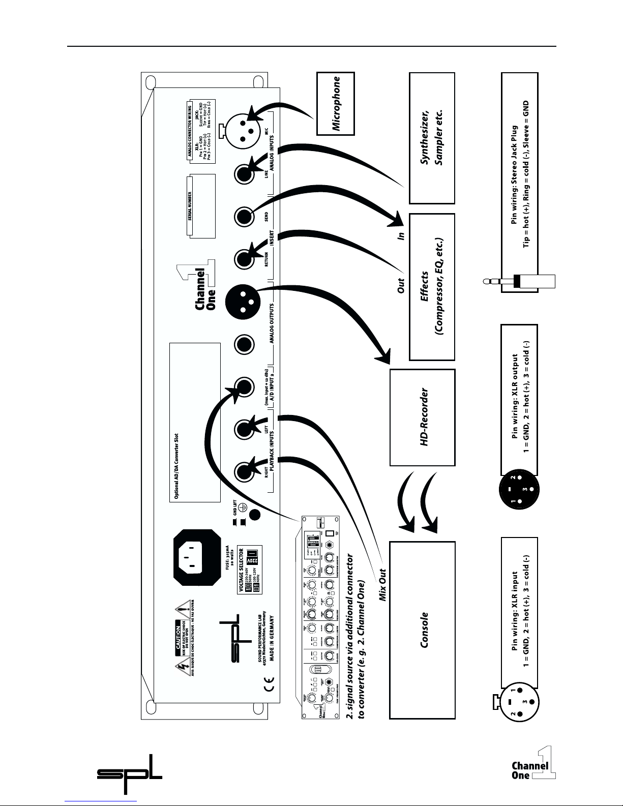
Connections
Rear Front / Wiring
Page 7
7
Connections
General Advises
Connections
Connectors
Again, while Channel One’s housing is EMV-proof and protects against HFinterference,placement of the unit is very important since it amplifies microphone signals as well as other unwanted signals. Before connecting the
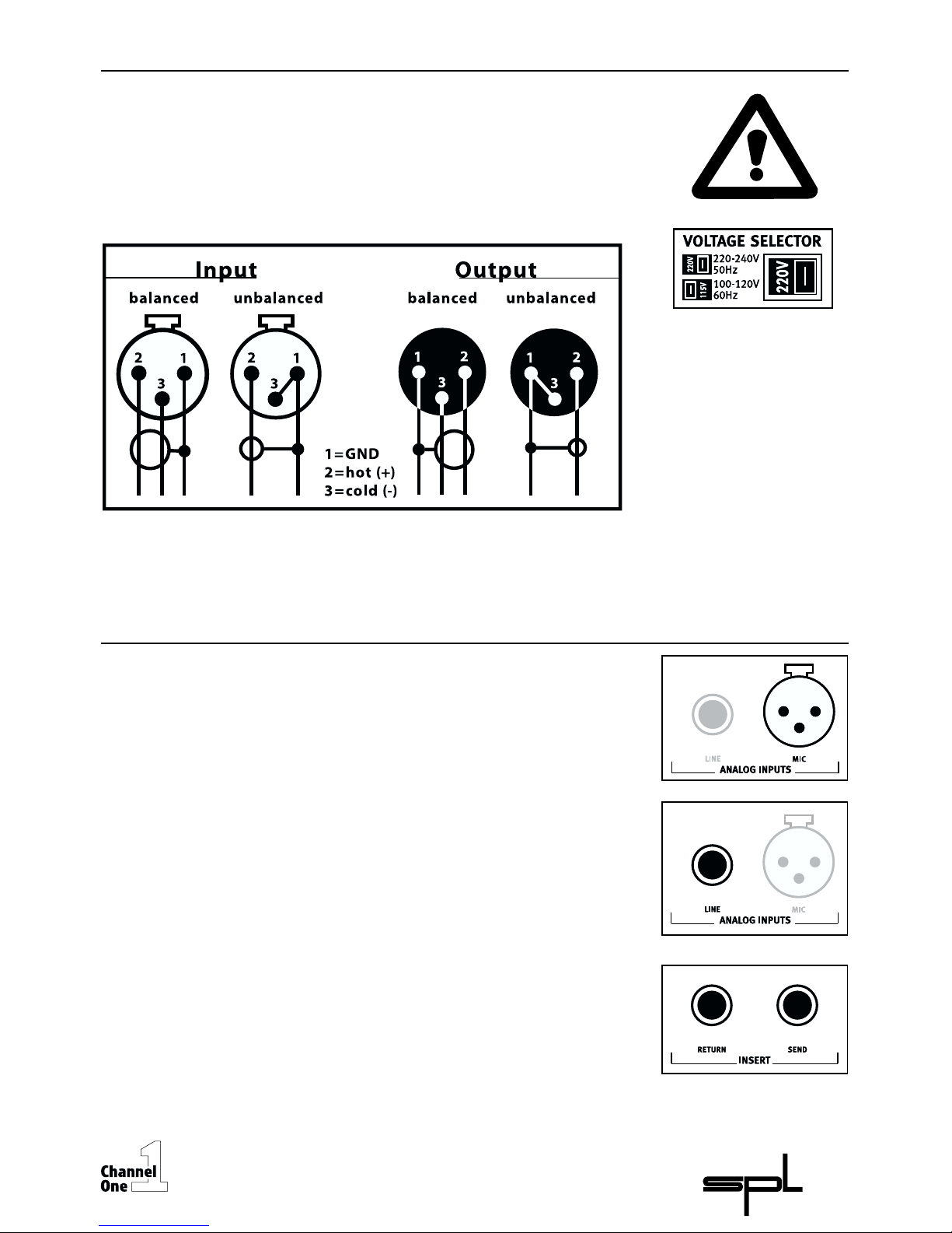
Channel One or any other equipment turn off all power. Adjust the voltage
setting on the back so that it corresponds with the power conditions.
The following graph shows the correct wiring for connecting unbalanced
signals to the balanced XLR connectors:
Unbalanced signals with mono jack plugs may easily be connected to the
balanced jack connectors without level differences (see “Analog Outputs“ on
page 8).
Mic connector
The Mic connector is used to plug in microphones of any type (dynamic,
condenser or tube microphones etc.). If 48 V phantom power is required for
some mics, switch on the 48 V button. For further information please read
“48 V-phantom power“ on page 9.
Line connector
The balanced Line connector serves to connect line level equipment. It is
recommended to route the Line input to a patchbay. This allows easy and
fast selection of various line signal sources.
Insert connectors
The balanced Insert connectors (Send and Return) are used to integrate
further units into the signal path of the Channel One.The Send connector is
placed behind the De-Esser, the Return connector is located in front of the
Compressor/Limiter. This also allows to record the pre-amplifier signal via
the Send connector while another input signal can be fed into the Channel
One’s Compressor/Limiter/EQ sections for further processing.
Page 8
8
Connections
Connectors
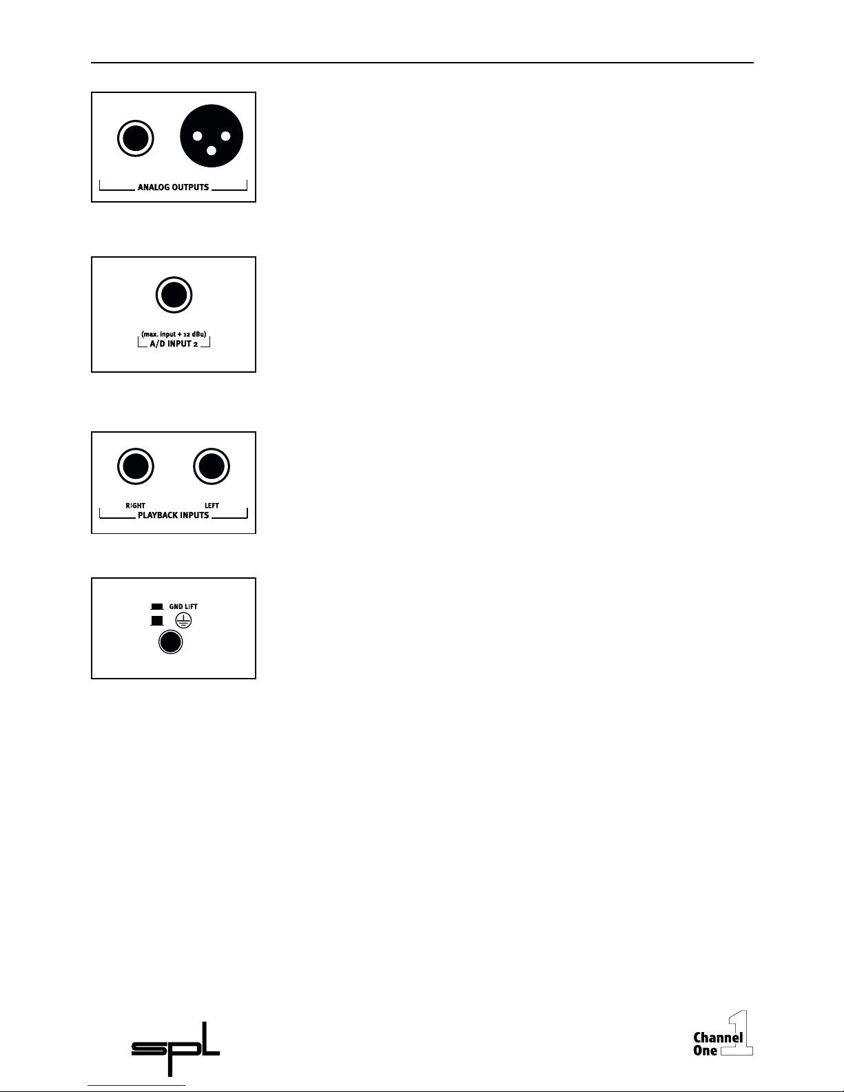
Analog Outputs
The Analog Outputs deliver balanced output signals. Lundahl output transformers can be equipped optionally.
Since both connectors are working in parallel, unbalancing one connector
also unbalances the other one.If for example a mono jack plug is connected
to the jack connector, the XLR connector is switched to unbalanced operation as well.
A/D Input 2
This connector serves to feed a further signal to the optional AD/DA
converter. Two different signals can be converted at the same time. If no
signal is fed to the A/D Input 2 connector,the output signal of the Channel
One is routed to both channels of the converter.The maximum input level
should not exceed +12dBu to avoid clipping of the converter (+12dBu
represents the digital full scale level,0 dBfs).
Playback Inputs
The playback signal is connected to the unbalanced Playback Input jacks to
direct it to the Headphone Monitor. If a mono playback signal is available,
only the Left connector must be connected.The signal will then be present
on both channels. The Right connector should be used, if only one channel
should appear on one side of the headphones. In contrast to all other
connectors the Playback Inputs are unbalanced.
GND Lift
The GND Lift switch separates internal ground from chassis ground. The
switch should be activated to eliminate ground loop humming which may
occur if the Channel One is connected to units with another ground potential.
Page 9
9
Operation
Pre-amplifier
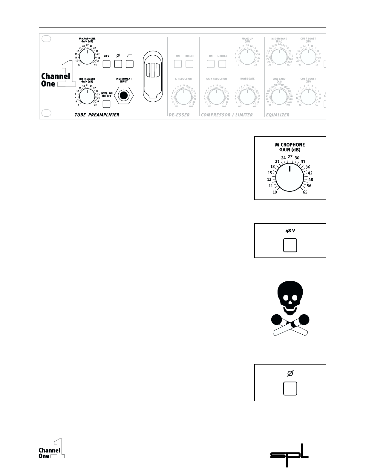
Microphone Gain
The Microphone Gain control determines the preamplification of the microphone signal. The preamplification values extend up to + 65 dB. If Lundahl
input transformers are fitted the scale values are to be increased by + 14 dB.
Please refer to "About levelling" on page 10 for further information.
48 Volt phantom power
The 48 Volt phantom power in the Channel One serves to supply condenser
microphones which are equipped with in-built preamplifiers. A precise
construction and disturbance free electrical supply are the main requirements for their trouble free operation. In the Channel One the voltage is
maintained at a precise 48 V and delivers a maximum current of 14mA. This
is sufficient for all types of microphones.
WARNING:All microphones with balanced, ground free output (including
tube microphones) can be operated with phantom power switched on.The
following procedure is to be adhered to: Firstly connect the microphone to
the Channel One, then switch on the phantom power – you can now
commence work.When recording has been completed firstly switch off the
phantom power then wait 30 seconds before disconnecting the microphone from the Channel One.This allows residual voltages to be discharged.
Phantom powering is only used with condenser microphones.With any
other type of microphone it is to be switched off ! An unbalanced microphone is not to be used with phantom power switched on!
Phase Reverse
The phase inversion function reverses the polarity of the microphone signal.
When the button is pressed the phase is rotated through 180º.The phase
inversion function is often useful, for instance to correct a headphone
monitor signal which is possibly wrongly phased. A singer/speaker can
actually hear himself during recording as well as over the headphones.
Incorrect polarity leads to an unnatural tone and to drastic tonal changes, if
the distance to the microphone is varied.We recommend that you check the
polarity and correct it if necessary before commencing recording.
Page 10

10
Operation
Pre-amplifier
Highpass
The Highpass filter is used to eliminate disturbing low frequencies. These
disturbances could impair the following processing or AD conversion. The
cut-off frequency at 50 Hz avoids influences to vocals. The roll-off is
12 dB/octave.
Instrument Gain
The Instrument Gain control determines the preamplification of the inputs
Line and Instrument.The signals can be preamplified from + 5 dB up to + 42
dB.By making use of the balanced line input the amplification is reduced by
about 18 dB to enable even very ”loud” signals to be processed. For further
information please read the next section “About levelling”.
About levelling
For perfect levelling of the preamplifier firstly switch off all other modules
(De-esser, Compressor/Limiter, EQ) and set the Output control to 0 dB.The
signal can now be levelled with the assistance of the PPM output display.To
achieve a good working level the values should range between 0 and +6 dB.
At these levels an optimal drive level
and enough headroom for further
processing (e.g. adding level in the EQ stage) is guaranteed.The Clip LED will
warn you of potential peaks;if during recording the Clip LED illuminates,the
preamplifying value is to be reduced accordingly.
Instrument/Line On – Mic Off
This button allows selection of the input source. The microphone signal is
available for processing when the button is not pressed; when pressed the
Instrument/Line signal is activated. As long as the Instrument Input at the
front of the unit is not in use the Line signal option on the back of the unit is
automatically available.
Instrument Input
The Instrument Input on the front of the unit is designed for the connection
of electric as well as acoustic guitars with their own pick up etc.This input is
of high impedance and designed for high amplifications. It is possible to
connect instruments with line levels, such as keyboards, samplers, drum
machines to the ”Instrument Input” to permit these to be processed quickly
with the Channel One, however it is preferable to connect line level equipment to the ”Line Input” at the back of the unit, ideally via a patch bay. Line
Input provides a more stable level (see section ”Instrument Gain”) while the
connection via a patch bay offers the most flexible routing method
combined with the advantage of insensitivity to disturbance characteristic
of balanced wiring.
Page 11

11
Operation
De-Esser
On
The first module behind the pre-amplifier stage is the De-Esser,which immediately removes disturbing S-sounds when required.The De-Esser module is
activated when the button is on. The S-Detect. LED in the display will show
that S-sounds are being detected regardless of the selected S-Reduction
value, in other words even when the button is switched off detection is still
shown in the display.
S-Reduction
With the S-Reduction control you can determine the intensity of S-sound
reduction. Because processing is undertaken from comparison with the
level of the entire frequency spectrum ( see next section ”Technical information ...”) the processing is more intensive with extreme S-sound levels than
with those of lower levels. After processing the output signal has a consistent S-sound level.
Technical information regarding the De-Esser
In contrast to common de-essers that influence a frequency band of about 2
octaves with compressor techniques the Auto-Dynamic De-Esser utilizes
filters that process only the reducible ”S-frequencies” but do not interfere
with the remainder of the spectrum.The S-frequencies that lie in the unpleasant range are automatically recognized, the phase is inverted and mixed
with the original signal. In this manner the disturbing frequency is quenched
and the hissing noise reduced.This method of operation has distinct advantages because it is unobtrusive and helps retain the original tonal quality.
Compressor-typical side effects such as lisping or nasal tones do not occur.
Finally its operation is as simple as pulling on the hand brake.
The reduction is accomplished by comparing the entire level with the individual S-sounds: the De-Esser functions only when the S-noise level exceeds
the average level of the entire frequency spectrum.This means for example
that original S-sounds with a determinate S-portion are not processed
whereas those that are too loud, or do not effectively contribute to the
sound,are reduced – the character of the voice remains unchanged.
info
Page 12

A further specialty is the integrated auto-threshold-function which makes
processing independent of the input level.Even when the speaker or singer
does not maintain a constant distance to the microphone, processing is
retained at the pre-set S-reduction value. Conventional systems are dependent on the input level and work more intensively as the distance to the
microphone is reduced.
The insert button activates any attachments of external equipments for
effects, equalizing or compression that are connected to the Insert
Send/Return loop on the rear of the Channel One. This binds them into the
signal chain thereby enhancing the processing capabilities ad infinitum.
The Insert point is located between the De-Esser and compressor. This
allows the ability to use the pre-amplifier stage/de-esser combination of the
Channel One separately from the compressor/EQ combination which,
because in this manner the Channel One can be used as 2 independent
units,broadens the range of uses enormously.
As long as units are not connected to the insert loop the signal flow is not
interrupted, even when the Insert button is pressed. The most flexible
method of use with the balanced designed insert sockets is to be achieved
by connection to a patch bay.
On
The On button activates the Compressor/Limiter/Noise Gate module.At the
same time the Gain Reduction display shows the processing intensity (see
section ”Gain Reduction”on page 13).
Usually the signal flow follows the design of the Channel One and for this
reason the input signal normally arises from the De-Esser or,when activated,
from the Insert. However with the Pre Comp.switch function of the Equalizer
module the Compressor/Limiter can be switched behind the Equalizer. This
allows it to be used either as an final compressor or limiter.(Further information in the section ”Pre Comp.”on page 15).
12
Operation
De-Esser
Operation
Insert
Operation
Compressor/Limiter
Page 13

13
Operation
Compressor/Limiter
Limit
The Limit button switches the Compressor to limiter mode. The Gain
Reduction control serves the purpose of controlling the threshold. The
Limiter does not function as a peak limiter, in other words there is no
guarantee that all peaks are intercepted. It is therefore advisable when
modulating a subsequent unit that a headroom of 2 to 4 dB remains. Peak
limiters have a system-based disadvantage in that audible distortions are
heard considerably sooner.
Gain Reduction
The Gain Reduction control sets the intensity of compression. Turning the
control clockwise increases compression.The working area spans between +
20 dB (counter clockwise limit) and -50 dB (clockwise limit).
The compressor applies the so-called ”soft-knee” characteristic, which
means that quiet passages are processed at a lower compression ratio than
louder passages. At maximal compression it operates with a ratio of 1:2.5 –
very effective dynamic limits are achievable when inconspicuous characteristics are to be processed.The exact development of the compressor curve is
portrayed in the diagram 1 on page 24. When setting the compression rate
the Gain Reduction display in the display field is of great assistance. The
effect on the selected compression rate is scaled in 1.5 dB steps. Depending
on signal source and dynamic structure the reduction values should lie
between 4 and 8 dB to restrict higher peaks and to optimize the operation of
the subsequent recording system.
Noise Gate
The Noise Gate control monitors the noise gate by which soft disturbances
are reduced during signal pauses. When turned fully counter clockwise the
noise gate is switched off.By turning the control in a clockwise direction the
threshold value increases. This means that the Noise Gate closes relatively
earlier.
The processing span of the Noise Gate is between –100 dB (gate control
turned fully counter clockwise) and + 18 dB (gate control turned fully clockwise). The Noise Gate is therefore operable over the complete dynamic
range.
With a hysteresis of 6 dB the noise gate functions very stably: the point at
which the Noise Gate opens lies 6 dB above the point at which the Noise
Gate closes again. Definite closure and opening is therefore assured – the
most feared characteristic of ”fluttering”is excluded. Even critical signals are
cleanly processed.
The release-time setting takes place automatically.The automation, which
depends upon the program, adjusts itself to the release time of the musical
piece thereby ensuring optimal (undetectable) opening and closing.
Page 14

14
Operation
Compressor/Limiter
Make Up
With the Make Up control the level reduction caused by compression or
limiting can be restored.With assistance of the Gain Reduction display in the
display field setting the Make Up control is very easy: If the maximal reduction value caused by the loudest tone amounts to -9 dB, for instance, the
Make Up control is also to be set to the value +9 dB. If the
Compressor/Limiter is now switched off the achieved gain in loudness will
be audible.
Technical Information regarding the Compressor/Limiter
In the Compressor/Limiter section of the Channel One the parameters for
the time constants (Attack and Release) are set automatically and adapt
themselves to the changing conditions of the input signal, far better than
can ever be achieved by manual adjustments.The transient and final oscillation behavior of voices and instruments are constantly changing and at
times are so erratic that a manual control will only achieve good average
values, which at critical moments can produce disadvantageous effects
(distortion and artifacts).
If for example the compressor has to react very quickly to harsh P or T
noises it must also be capable of reacting slowly to softer tones – otherwise
distortion occurs. Accordingly the Channel One Compressor/Limiter regulates the level of large fluctuations faster than smaller ones; tones of longer
duration are automatically processed with a longer attack time to prevent
distortions.
Even the control of the release time is dependent on the input signal. Fast
and large level fluctuations are correspondingly processed with shorter time
constants than minor fluctuations in order to limit the distortion of the
audio signal as far as possible. Overall this technique provides the optimal
solution between fast,unobtrusive control response and the least distortion
of the audio signal.The result is a natural and transparent sound impression.
A further technical specialty of the circuitry contributes to the high audio
quality of the Compressor/Limiter in the Channel One: the Double-VCADrive®.Two That 2181 VCAs are utilized, one receives the in-phase, the other
the out- of-phase signal. Subsequently the signal is passed through a differential amplifier. The effect of this circuitry is that distortion products and
offset fluctuations are removed. The product of the differential of both
signals (simply stated) means that possible interference is canceled out.The
original information is however further amplified by 6 dB. In addition the
VCAs provide relief to each other because they share their loads.They do not
run the danger of operating in the saturation range – this would lead to
offset noises,audible as clicks or pops.
The Double-VCA-Drive® circuitry overall displays vastly improved distortion values so that a distinctly clearer and more transparent sound impression is achieved than with conventional circuitry.Voices and instruments are
given a considerably more natural and dynamic timbre whereas ”muffled”
tones are not audible.
The Compressor/Limiter characteristics are portrayed on page 24.
info
Page 15

15
Operation
Equalizer
On
The On button inserts the Equalizer module into the signal path. Under
normal circumstances the input signal comes from the compressor.With the
Pre-comp button the Equalizer can be switched in before the Compressor/
Limiter so that the input signal is received from the De-Esser or Insert.
Pre Comp.
The Pre Comp. button reverses the sequence of Compressor/Limiter and
Equalizer: When the button is pressed the Equalizer operates in front of the
Compressor/Limiter; when not pressed the succession remains unchanged.
This function permits very flexible operation with the Channel One when it
is necessary to resolve recurring problems or to create special sounds.
The following example describes when the Equalizer (EQ) is to be switched
in front of the Compressor/Limiter.
When over-accentuation of instruments or voices is registered within
certain frequency ranges these ranges should first be reduced with the EQ.
The signal can subsequently be compressed more easily.If not done in this
sequence the compressor would react very strongly to these ranges; subsequent equalization would mean that the compression would be clearly
audible (the problem frequencies would then be too soft).A further sensible
application of the Pre Comp. function is the use of the compressor module
as a limiter to maintain a stable output level. If the EQ was to be used again
after limiting it could not be guaranteed that the output level would not
alter.
Air Band
The high frequency filter in the equalizer module is described as the ”Air
Band” and serves the processing of the frequency range of 2 and 20 kHz. A
coil-capacitor-filter with so called bell characteristics and a center frequency
of 17.5 kHz comes into operation here. At this frequency the maximum
possible accentuation is +10 dB, the maximum possible damping is -10 dB.
The characteristics of the Air Band filter are shown in diagram 2 on page 24.
Page 16

16
Operation
Equalizer
The ”soft” and natural tonal property, characteristic of the coil-capacitor
filter, lends itself extremely well to provide clarity to vocals in the upper
frequency range thereby improving their presence.On the other hand harsh
sounds can be lent a more pleasant sound characteristic through damping.
Mid-Hi Band
The center frequency of the semi-parametric mid high frequency filter is set
with the Mid-Hi Band control. The frequency range can be set between 650
Hz and 13.7 kHz so that this filter covers a range of 4.5 octaves and can be
equally employed in the lower mid as well as the high range.
Cut/Boost (Mid-Hi)
The Cut/Boost control determines the boost, or cut of the Mid-Hi filter; the
maximum values lie between +/- 12 dB.The Mid-Hi filter utilizes the proportional-Q-principle. In other words the bandwidth is dependent on the
selected boost or cut.The higher the boost or cut values are set,so the bandwidth becomes narrower; by low boost or cut values the bandwidth
increases (the exact curve of the Mid-Hi filter can be seen in diagram 3 on
page 25).This filter characteristic permits a musically more sensible processing of the frequency spectrum than with constant-Q filters: if a more
thorough setting has been chosen this will lead to far preciser definition of
the frequency range to be processed.This in turn minimizes influences from
adjacent ranges.
This filter construction permits the complete scope, from selective
removal of accentuated frequencies through to character giving accentuations of an instrument,to be effectively and quickly covered.
Low Band
The center frequency of the half-parametric bass filter is set with the Low
Band control.The adjustable frequency range lies between 30 Hz and 720 Hz
so that this filter covers a range of about 4.5 octaves,allowing it to be used
from the deepest bass to the lower mid range.This together with the Mid-Hi
filter ensures that the entire frequency spectrum is covered.
Cut/Boost (Low)
The Cut/Boost control determines the boost or cut of the Low Band filter;the
maximum values lie between +/- 14 dB. The Low Band filter also operates to
the proportional-Q-principle, in other words the bandwidth is dependent on
the selected boost or cut.With the Low Band filter the factor with which the
relationship of the boost or cut values,in relation to the bandwidth, is determined lies somewhat higher than with the Mid-Hi filter. The bandwidth is
therefore marginally narrower at maximum boost than with the Mid-Hi filter.
The exact curve of the Low Band filter is shown in diagram 4 on page 25.
Page 17

17
Operation
Equalizer
The Low Band filter can be applied in many ways. Examples are; to accentuate the fundamental sound of a voice, to cut ”boom frequencies” and for
placement of bass emphasized instruments such as bass guitar,bass drumsor synthesizers during recording or subsequently when mixing etc.
Recommendation on frequency settings: To find the frequency which is
to be processed as quickly and accurately as possible the Cut/Boost control
should firstly be adjusted to the maximum position. Subsequently the relevant frequency should be sought. Following this the required boost or cut
can be set with the Cut/Boost control.Because the filter at maximum setting
works with the smallest bandwidth the frequencies can be heard most
distinctly at this setting,making them easier to locate.
Distortion
The Distortion control offers the capability of applying distortions to
signals. The distortions are infinitely variable from Off through to distinctly
perceptible harmonics. The distortion stage is located in front of the equalizer so that the even newly created spectrums can be processed with the
EQ.
The overmodulated field-effect transistor which forms a part of the distortion circuitry has a similar characteristic curve as a tube and sounds distinctly ”warmer” than a pure diode- distortioner.
The signal level is of utmost importance to the operating mode of the
Distortion module.To achieve useful results the level should lie in the range
0 to + 6 dB. Over and above this the results are strongly dependent on the
condition of the input signal and its spectrum. The processing of sinewavelike signals (e. g. E-piano, vocal, guitar) is audible much earlier than signals
with predominant harmonical contents (e. g. snare drum, hi hat etc). It is
recommended that time and effort is taken to find the correct setting.
IMPORTANT: To avoid exasperation during recording it is recommended
that the EQ controls,in particular the Distortion control, are initially set to Off
or 0! If not, tonal changes will occur immediately and furthermore, in the
case of the Distortion control, additional distortions.
Page 18

18
Operation
Output
Output
The outgoing signal can either be dampened to –20 dB or further amplified
by +6 dB with the Output control to provide optimal drive to the subsequent units or the optional AD/DA converter. The individually selected
output level is shown on the PPM-Output display in the display field.Before
a recording commences the Output control should be set to 0:The uninfluenced values from the Output control are then legible and available for
adjustment of the pre-amplifiers levels.
Mute
The Mute switch mutes the output signal; when activated the PPM-Output
display does not show any values. An instance of a sensible application
could possibly be when the output signal of the Channel One,together with
the playback signal, are reproduced via the studio monitors during a recording session.When subsequently the recorded take is monitored it becomes
possible to hear extraneous singing or comments arising from the singer. It
is therefore advised to press the Mute switch to permit listening to a clean
recording. Do not forget to deactivate the Mute switch before continuing
recording.
Another instance could be allowing the musician to practice for a while
and then,when ready,freeing the signal path and commencing recording by
deactivating the Mute switch.
Page 19

19
Operation
Headphone Monitor
Playback
The Playback control regulates the volume of the playback signal which is
passed to the musician. There are two methods of passing the mono playback signal: The first is to pass the music to both ear pieces of the headphone in which case ”Playback Input Left” must be connected. On the other
hand some musicians want to hear the playback signal through only one ear
piece so they can hear ”directly” with the other ear. In this instance connect
”Playback Input Right”and set the Volume control to Off.
Volume
The Volume control regulates the volume adjustment of the microphone,
instrument or line signal. The setting is independent to that of the Output
control or Mute switch, which means the volume in the headphones does
not alter although the output value of a modulation has changed.
With the Playback and Volume controls an individual mix for the headphones is achievable:it is advisable to ask the musician before recording starts
whether he can hear himself and the playback adequately.The best conditions
for good intonation, stemming from a relaxed working environment, prevail.
Another practical use of the headphone monitor module is to monitor the
signal quality directly to locate and eliminate possible interference rapidly.
Recommendation on using the Headphone Monitor: When working
with hard disc systems or digital mixing consoles latency may be present.
Flanging or phasing effects occur if the musician receives the monitor signal
with a time lag. It is therefore recommended, to obviate latency, that the
monitor signal passes directly from the headphone monitor to the headphones. It should be remembered that the recording signal has not been
picked up again by the playback signal because phase quenching can occur
when the same signal is mixed by both the Playback and Volume controls.
Phones
The Phones socket is provided for the connection of stereo headphones.The
high quality headphones amplifier is of low impedance and has low distortion values so that all current types of headphones can be connected to
monitor the signals with highest possible audio fidelity.
Page 20

20
Operation
Displays
S-Detect.
The S-Detect.LED shows when S-sounds have been detected. It is only active
when the De-Esser is switched on and is independent from the selected SReduction setting.
Clip
The Clip LED shows overload in the unit. The clipping level of the LED lies
approximately 2 dB below the internal full scale (conforms to + 19 dBu).The
Clip LED should flash as seldom as possible.
At all relevant points of the signal flow the display gets read off: behind the
Pre-amplifier, behind the Compressor/Limiter, behind the EQ and behind the
Output control. All possible causes for overload can be directly checked
(overdriven Microphone/Instrument/Line Gain, an excessive Make Up value
in the Compressor/Limiter, too much boost in the EQs or too high output
level).
Possible causes of overload can be quickly detected by simply switching
off the modules individually. If overloads occur during recording the
quickest remedy is to gradually reduce the Gain control in the Pre-amplifier.
Signal
The Signal LED illuminates when a signal is being received at the Pre-amplifier. This provides a quick method of checking that a signal source is
correctly connected.All levels above -50 dB are covered.
Warm Up
The Warm Up LED gives an indication regarding the warm up phase of the
tube stage. When the LED is extinguished the Channel One is ready for
operation;it is possible that before this has occurred the output signal is low
and sounds distorted.
Page 21

21
Operation
Displays
Power Supply
Gain Reduct.
The Gain Reduct. display provides information about the processing being
undertaken with the Compressor/Limiter or the Noise Gate.The level change,
perhaps caused by compression, are scaled in 1.5 dB steps. The display is
activated when the Compressor/Limiter module is switched on.
Noise Gate operation is visible because all Gain Reduct. LEDs illuminate
when the signal level lies under the gate threshold setting.
PPM Output
The PPM Output display shows the peak reading of the output level (calibrated to 0 dB) and is present at the analog outputs on the rear of the unit.
This display also serves to the pre-amplifying Gain. The value ”0dBFS”
marked on the left side represents the maximum level of the optional AD/DA
converter which should not be exceeded. (Further information is given in
the directions to the AD/DA converter).
Although the values of the PPM Output display only cover up to + 12 dB
sufficient headroom remains internally (approximately 6 dB) so that the
output value can exceed this limit without causing clipping. The range of
optimal noise performance lies between 0 and + 9 dB.
Built around a torroidal transformer,the power supply allows for a minimal
electromagnetic field with no hum or mechanical noise. The power supply's
output side is filtered by an RC circuit to extract noise and hums caused by
your power service.6000µf capacitors smooth out the positive and negative
half waves.
The phantom power is derived from a separate winding in the transformer,
a precise current regulator a clean phantom power of 48 volts. Our high
quality 0.1%/ 6,81kOhm resistors ensure the pristine quality of the phantom
power supply.
The 250 Volt power supply for the tube stage is filtered with 300 µF to
minimize hum.
The supply voltage can be set to 230 V/50 Hz or 115 V/60 Hz . Check your
country's power requirements for the appropriate setting.An AC power cord
is included to feed the IEC-spec, 3-prong connector. Transformer, AC cord
and IEC-receptacle are VDE,UL and CSA approved.The main fuse is rated at
315mA.
Chassis ground and AC ground can be physically disconnected by the
“Ground Lift”switch (GND LIFT).This helps to eliminate hums.
Page 22

22
Specifications
Measurements
Microphone Input
Frequency Response: ..................................... 10 Hz-100 kHz
(100 kHz = -3 dB)
Common Mode Rejection: ............................ 1 kHz:-80 dB / 10 kHz:-78 dB
(@ -20 dBu)
THD & N: .............................................................. Amplification: A weighted:
20 dB -97,1 dBu
40 dB -91,1 dBu
65 dB -69,4 dBu
Dynamic Response: ........................................ 118 dB
Line / Instrument Input
Frequency Response: ..................................... 10 Hz-100 kHz
(100 kHz = -3 dB)
Common Mode Rejection: ............................ 1 kHz:-80 dB / 10 kHz:-78 dB
(@ 0 dBu,only Line Input)
THD & N: .............................................................. Amplification: A weighted:
5 dB -99,4 dBu
20 dB -97,2 dBu
42 dB -79,4 dBu
Input Impedance: ............................................. Line: 20 kOhm / Instrument: 1 MOhm
Max.Input Level: ............................................... Line: +22 dBu / Instrument:+14 dBu
Dynamic Response: ........................................ 119 dB
Outputs
Max.Output Level XLR / Jack: ...................... +20 dBu
Output Impedance: ........................................ <50 Ohm
Dimensions
Housing ............................................................... Standard-EIA-19“/2 U
... 482 x 88 x 210 mm
Weight ............................................................... 4,15 kg
Page 23

23
Block Diagram
Channel One,Model 9945
© 1999 SPL electronics GmbH.
Page 24

24
Measurements
Compressor/Limiter,Air Band
Diagram 1 shows
various curve
characteristics for
the Compressor/Limiter
The reference curve A
displays the relation
between input and output.
Curve B shows the curve
characteristics of the
Compressor.
The soft knee characteristic
is clearly visible.
Curve C portrays the limiter’s
curve characteristics.
Diagram 2 shows various
cut and boost settings of
the Air Band filter.
A
B
C
Page 25

25
Measurements
Mid-Hi filter,Low filter
Diagram 3 displays
various cut and boost
settings of the Mid-Hi filter
at 3 kHz.
The proportional-Q
characteristic is
distinctly visible.
Diagram 4 displays
the curves of the
Low Band filter.
Various cut and boost-
settings at 150 Hz.
Again the proportional-Q
characteristic is
clearly to see.
Page 26

26
Warranty
SPL electronics GmbH (hereafter called SPL) products are warranted only in
the country where purchased,through the authorized SPL distributor in that
country, against defects in material or workmanship. The specific period of
this limited warranty shall be that which is described to the original retail
purchaser by the authorized SPL dealer or distributor at the time of
purchase.
SPL does not,however,warrant its products against any and all defects:
1) arising out of materials or workmanship not provided or furnished by SPL,
or 2) resulting from abnormal use of the product or use in violation of
instructions, or 3) in products repaired or serviced by other than authorized
SPL repair facilities, or 4) in products with removed or defaced serial
numbers, or 5) in components or parts or products expressly warranted by
another manufacturer.
SPL agrees, through the applicable authorized distributor, to repair or
replace defects covered by this limited warranty with parts or products of
original or improved design, at its option in each respect, if the defective
product is shipped prior to the end of the warranty period to the designated
authorized SPL warranty repair facility in the country where purchased, or to
the SPL factory in Germany, in the original packaging or a replacement
supplied by SPL, with all transportation costs and full insurance paid each
way by the purchaser or owner.
All remedies and the measure of damages are limited to the above services.
It is possible that economic loss or injury to person or property may result
from the failure of the product; however,even if SPL has been advised of this
possibility, this limited warranty does not cover any such consequential or
incidental damages.Some states or countries do not allow the limitations or
exclusion of incidental or consequential damages, so the above limitation
may not apply to you.
Any and all warranties, express or implied, arising by law, course of dealing,
course of performance, usage of trade, or otherwise, including but not
limited to implied warranties of merchantability and fitness for particular,
are limited to a period of 1 (one) year from either the date of manufacture.
Some states or countries do not allow limitations on how long an implied
warranty lasts,so the above limitations may not apply to you.
This limited warranty gives you specific legal rights, and you may also have
other rights which vary from state to state,country to country.
SPL electronics GmbH
41372 Niederkruechten, Germany
Page 27

27
Copy Master
Page 28

28
Manual
Notes
.............................................................................................................................................
.............................................................................................................................................
.............................................................................................................................................
.............................................................................................................................................
.............................................................................................................................................
.............................................................................................................................................
.............................................................................................................................................
.............................................................................................................................................
.............................................................................................................................................
.............................................................................................................................................
.............................................................................................................................................
.............................................................................................................................................
.............................................................................................................................................
.............................................................................................................................................
.............................................................................................................................................
.............................................................................................................................................
.............................................................................................................................................
.............................................................................................................................................
.............................................................................................................................................
.............................................................................................................................................
.............................................................................................................................................
.............................................................................................................................................
.............................................................................................................................................
.............................................................................................................................................
 Loading...