

Page 1
Manual
Atmos 5.1 Surround Miking System
Page 2

2
Version 1.0 E – 12/2003
R&D: Wolfgang Neumann
This user's guide contains a description of the product. It in no way represents
a guarantee of particular characteristics or results of use. The information in this
document has been carefully compiled and verifi ed and, unless otherwise stated or
agreed upon, corr ectly describes the produc t at the time of packaging with this document.
Sound Performance Lab (SPL) continuously strives to improve its products and
reserves t he right to modify the product de scribed in this manual at any time without
prior notice. This document is the property of SPL and may not be copied or reproduced in any manner, in part or fully, without prior authorization by SPL.
Special thanks to:
Gerd Jüngling from ADT, who kindly provided the circuitry for the surround panning
matrix. Dirk Brauner Röhrengerätemanufaktur for the good collaboration.
Contact
Sound Performance Lab
Sohlweg 55, 41372 Niederkruechten, Germany
Fon +49 (0) 21 63-98 340
Fax +49 (0) 21 63-98 3420
Mail: info@soundperformancelab.com
Internet: ww w.soundperformancelab.com
Atmos 5.1 Surround Miking System, Model 9843 User’s Guide
© 2003 SPL electronics GmbH. All rights reserved. Technical specifi cations and appearance subject to change without notice.
Page 3

3
Contents
Atmos 5.1 – the complete miking system for surround recordings ................... 4
Installation ........................................................................................................ 5
Control Elements ............................................................................................... 6
Standard Recording Setup ................................................................................ 11
Integration of additional microphones/stereo submix ...................................... 12
Integration of additional microphones/stereo submix ...................................... 13
A typical recording setup .................................................................................. 14
Specifi cations ................................................................................................... 15
Block diagram ................................................................................................... 16
Introduction
Dear customer,
thanks for using the Atmos 5.1 system. We wish you have as much fun working with
it as we had during the development of this extraordinary recording equipment.
The complete Atmos 5.1 system includes Atmos 5.1 controller, the Adjustable
Surround Microphone 5 (ASM 5), a separate power supply unit and a multicore cable
(length ca. 25 meters/27.5 yards).
The Atmos 5.1 system allows to record the original event and all of its authentic
spatial content with highest precision. It demonstrates the signifi cant difference
between discrete surround recordings and artifi cial surround mixes with breathtaking results. To reliably achieve these amazing results, the Atmos 5.1 provides
everything you need to record virtually any audio event.
Due to its analog structure, the audio signals are compatible with any common
surround format—DVD-A, DVD-V, SACD, AC3, DTS, MLP... you name it, Atmos 5.1 can
deliver it.
With its ingenious ASM 5 „star frame“ array based on Brauner VM1 mic elements
and custom-designed, hand-built Atmos 5.1 controller, this unique system offers an
unparalleled combination of uncompromising audio quality and ultimate fl exibility.
Most importantly, the Atmos 5.1 system is a breeze to use and can be set up in
minutes, arming you for the most convincing 5.1 recordings you‘ve ever experienced.
Page 4

4
The Atmos 5.1 is a fully-featured stand-alone surround miking system for surround
productions in any known format.
The ASM 5 surround microphone combines fi ve microphones elements in an ideal
setup for surround recordings. Each one is directly assigned to one of the fi ve
surround channels and can be processed discretely with the Atmos 5.1 controller. All
microphone elements are movable and their polar patterns can be set up individually, e g. to effectively compensate for disadvantageous room acoustics.
The Atmos 5.1 features a complete panorama matrix , an LFE section and a monitoring
section, thus all you need to create a surround mix. An External Inputs section allows
to integrate additional stereo mixes in a surround mix—either for the inser tion of
additional microphones or to upgrade stereo consoles with surround capabilities.
The Atmos 5.1 system operates fully analog to ensure independence f rom any storage
or transmission format.
The ASM 5 surround microphone
The ASM 5 is based on Brauner VM1 mic elements. Three microphone elements are
assigned to the L/C/R channels, two further mics are used two capture the information for the rear surround channels. Together they form a per fectly balanced surroun d
microphone.
Each microphone head can be moved by +/- 90° horizontally, the polar patterns can
be adjusted remotely from the Atmos 5.1’s ASM5 Pattern Control—infi ntely variable
for each capsule from omnidirectional through cardioid/hypercardioid to fi gure-ofeight. A pad switch allows to reduce the microphone’s sensitivity by -16 dB.
The I/Os of both the ASM 5 and the Atmos 5.1 are built upon transformers to drive
wirings of up to 250 meters/275 yards. The ASM 5 can be installed on usual microphone stands.
Atmos 5.1 controller
The Atmos 5.1 is equipped with fi ve matched high precision microphone preamps
featuring SPL‘s triple gain stages to capture the superb sound of Brauner‘s ASM 5
microphone in the most transparent, noiseless and uncoloured way.
The microphone preamps also feature SPL‘s S e r v o Drive-Te c h n ology which detects
voltage differen ces (DC-offset) bet ween the positive and nega tive paths of the amplifying stages. Any offset increases noise and distortion and therefore compromises
the signal quality. ServoDrive minimize s DC-off sets to values between 0mV and 2mV.
The recorded signal contains less noise and distortion and improved tonal transparency.
Further features include Lundahl input transformers, pads, phase reverse, phantom
power, low cut fi lters, a switchable insert and tape send/returns. All switches are
luminated. High quality switches and relays with gold plated contacts are used
throughout.
Motorized gain controls
An important feature of the Atmos 5.1 are it s motorized gain controls. While chang ing
the preamplifi cation the relative loudness relationships between all fi ve microphones
are maintained.
A Master Gain switch enables motorized control over all fi ve microphones preamplifi ers by just turning one control. This is especially impor tant when re-adjustment of
the preamplifi cation becomes necessary during recording to avoid negative effects
on the spatial coherence and phase stability.
Atmos 5.1 – the complete miking and system for surround recordings
Page 5

5
The Atmos 5.1 unit and the PSU should not be installed near units which produce
strong magnetic fi elds or extreme heat. Do not install the units directly above or
below power amplifi ers. Especially the ventilated PSU should be installed at a place
with suffi cient air circulation.
The ASM 5 has to be placed the way that the LCR heads of the microphone (those
closer to the microphone center/90° angle) are facing the sound source. Be sure to
place the microphone as high as necessary to avoid ground refl ections and comb
fi ltering effects. Usually the best position for the ASM 5 is right on the crossing
between the direct sound fi eld and the dif fuse sound fi eld.
BEFORE switching on the PSU, you have to connect the ASM 5 via the multicore lead
to the Atmos 5.1 unit. Pay attention to fi t the bayonet joints properly. Proceed in the
same way to connect the Atmos 5.1 unit to the PSU. Check that the voltage details
quoted on the PSU back panel correspond to your local mains electricity supply. Use
a minus (-) screwdriver to set the voltage selector to the required voltage.
By the way ... the PSU uses two 1,6 A slow fuses.
On the Atmos 5.1 unit, please check the positions of the ASM 5 Pattern Controls. We
recommend to start with the cardioid pattern characteristic for all fi ve microphones
(controls in center position).
Please check the position of the External Mic Input switches on the back panel of the
Atmos 5.1. If these switches are depressed, the corresponding channels of the ASM
5 are deactivated. Depress them only to activate external microphones connected to
the XLR inputs.
Now switch on the PSU. Check the 9 LEDs on the front panel of the PSU. They indicate that all 9 voltages are generated properly. Chassis ground and AC ground can
be disconnected with the Ground Lift switch (GND LIFT) on the back panel. This can
help to eliminate hum. An AC power cord is included to feed the IEC-spec, 3-prong
connector.
After switching in the PSU, proceed as follows:
1) Turn the Mic Gain of Channel 5 (master) control fully counter clockwise (0 dB).
2) Press the Channel Lock button at Channel 5 (all other channels follow automatically to 0 dB).
3) Set the Master Mic Gain control to the 12 o’clock position (all other mic gain
controls follow precisely). Now the VU meters indicate modulation.
4) Set the Fader controls to the 0 dB posit ion (used for monitoring only, see “St andard
Recording Setup“).
5) Press the Direct but ton on every channel to route the signal directly to the Master
and Monitoring Outputs.
6) In the Monitor section, set the control to the 12 o’clock position. The L/R switch
has to be activated for 5.1 monitoring.
Installation
Page 6

6
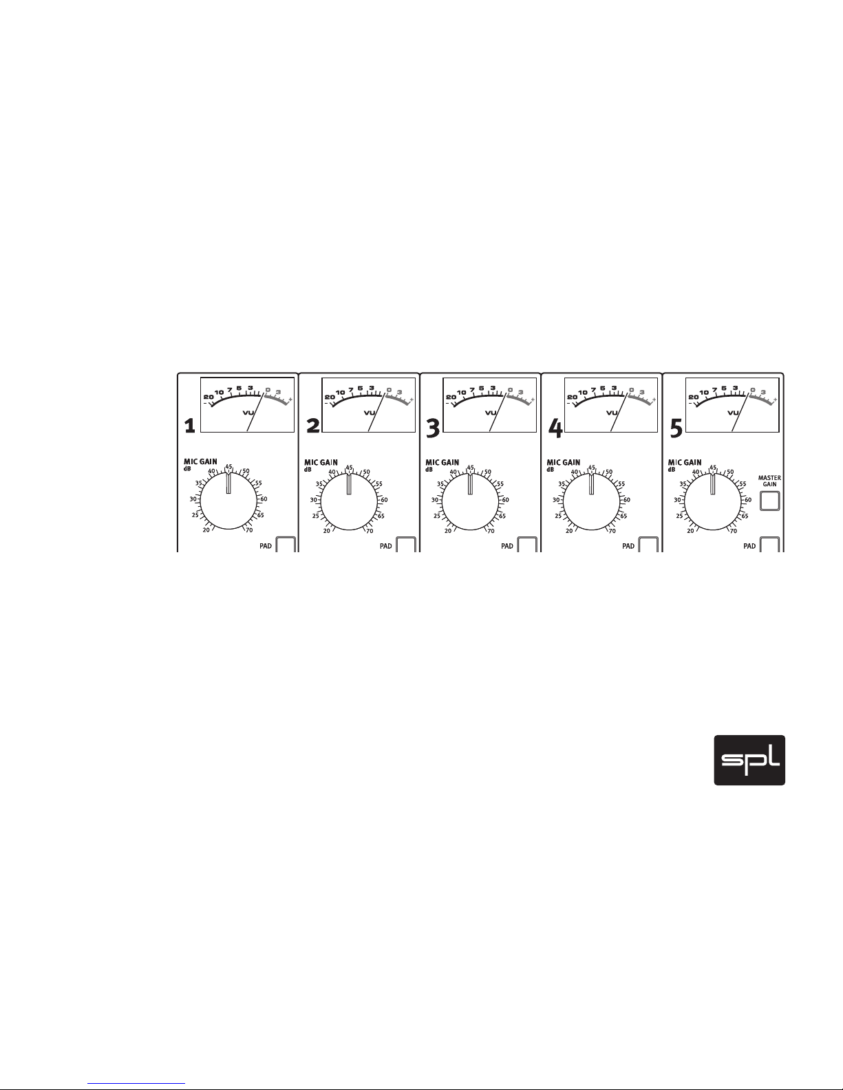
Input Section
Gain settings can be adjusted individually for each channel. The MIC Gain control
of channel 5 can be specifi ed as Master Gain control to control all 5 gain settings at
a time—the motorized potentiometers ensure coherent gain settings for all channels with highest precision.
The microphone inputs are equipped with phantom power supply, switchable
insert, pad (-25 dBu), phase reverse and high pass fi lter (10 0 Hz/50 Hz).
For direct recordings of the preamplifi ed signals recording devices like a multitrack
recorder can be connected to the insert Tape Send. Signals coming back from the
recorder can be connected to the insert Tape Return, for example to use the panorama matrix or further Atmos 5.1 features.
The VU meters display the input level of each channel after the preamplifi er
stages.
The insert Tape Return ca n als o be u sed l ike a usual line input for e xternal sources,
e g. to use all Atmos 5.1‘s features for a surround mix.
Fader
The fader allows adjustments of the signal level that is routed either to the direct
channel outputs, to the panorama matr ix or to the outputs.
Control elements
Page 7

7
5.1 Routing
The Atmos 5.1 controller offers a complete routing and panorama matrix. With the
routing selectors the signals can be assigned to any of the the surround busses,
with the panorama matrix they can be po sitio ned ex actl y. The D irec t swit ch allo ws to
bypass the panorama matrix, routing the signal to the output of a sur round bus.
F/S Pan
Front/Surround Pan blends the signal from the front to the rear channels or vice
versa.
Control Elements
Page 8

8
L/C/R Pan and Divergence
L/C/R panning determines the position of a signal in the L/C/R panorama. The divergence control allows to attenuate the L and R channels in relation to the center
channel.
LFE signals
The LFE signal can be composited from the front, surround, and centre channels. A
24 dB Butterworth low-pass fi lter at 130Hz can be activated to only let those frequen cies pass up to where localisation begins. In the mixing/premastering stage the
frequency can be reduced to the value required for i.e. AC3 or DTS encoding. If the
low-pass fi lter is not activated, a mono composite of the selected mic inputs can be
send to a separate sub/LFE processor.
Control elements
Page 9

9
Stereo In/Out
Two additi on al balanced inputs are provided to mix a stereo source from additional
room mics or from a multic hannel sub mix to the front, centre and surround c hannels.
The stereo outs allow the stereo source to be processed or recorded with further
units.
Mic Distance
Two sw it ch able allpa ss stereo wid th controls can be used to infl uence the stereo
width of each coherent channel pair (L an d R, LS and LR) . T his way, va ria ble dis tan ce s
between the microphone heads can be simulated electronically. The Mic Distance
section is equipped with a hard bypass and a mono switch. Two phase meters display
the L/R & SL/SR correlation (either with Mic Distance control active or in bypass).
Control Elements
Page 10

10
ASM 5 Pattern Control
The ASM 5 provides infi nitely variable adjustment s of the polar pattern charac teristic
for each microphone from omnidirectional up to fi gure-of-eight. These adjustments
can be made remotely from the Atmos 5.1 and can be monitored while recording.
A pad reduces the microphone‘s sensitivity by -16 dB.
Monitoring
Both during recording and mixing the monitoring volume can be adjusted by the aid
of an electronic circuitr y that ensures precise, coherent volume control of all six ch annels. The Monitor Volume control also sets the volume for headphones connected to
the front. The 5.1/Stereo switches determine which channels are monitored.
PPM Meters
The PPM meters display the levels at the output of each bus. Values range between
-48 dBu und +9 dBu and are displayed in steps of 3 dB.
Control Elements
Page 11

11
The Standard Recording Setup is the basic
confi guration for “purist” 5.1 recordings. The
DTRS is connected right after the preamp stage
to record unprocessed microphone signals.
Additionally the 6th recorder’s channel can be
used to record the sub bass signals, the 7th
and 8th channel can be used to record a stereo
mixdown.
This setup can be modifi ed or extended in many
ways, for example by connecting an analogue
multitrack recorder to the ma ster outputs (up to
two recorder simultaneously via XLR and Jack)
for recordings of the processed signals – while
the DTRS still is recording as described above
(e. g. backups).
When using a stereo headset, the L/R, C, SL/SR
and SUB channels can be monitored individually (see Monitor section).
Insert Sends (XLR or Jack)
to DTRS inputs
ASM 5
Sub Bass (XLR or Jack)
Stereo Mix (XLR or Jack)
DTRS outputs to Insert
Returns (XLR or Jack)
5.1 Monitoring
Standard Recording Setup
Page 12

12
Integration of additional microphones/stereo submix
Stereo master outs to
External Inputs L & R
Additional microphones
The Atmos 5.1 controller allows to integrate
additional microphones as stereo or surround
submix. During m onitoring, the level sett ings for
the ASM 5 determine the mix relation bet ween
ASM 5 and additional microphones.
In general additional stereo mixes can be
connected to the External Inputs. For integration of additional microphones as a stereo mix,
an external sub mi xer, connected to the External
Inputs L&R, is ne eded to create the mix .
Page 13

13
Integration of additional microphones/surround submix
5.1 master outs to XLR Returns of the Atmos 5.1
Additional microphones
Atmos XLR sends
to DTRS or DA SH
For insertion of additional surround submixes,
the Insert Send and Insert Return sockets on
the Stmos 5.1 rear panel must be connected
with a short patch cable. The Inser t buttons of
the Iput section on the front panel need to be
depressed.
The additional surround mix is created on
a mulitchannel-ready submixer and and
connected to the XLR Insert Returns of the
Atmos 5.1 controller.
The signals can be sent to a DTRS/DASH via the
XLR Insert Sends on the Atmos 5.1.
Page 14

Fliess
14
A typical recording setup: SACD recording with Atmos 5.1 and additional microphones
Page 15

15
Frequ ency range
Mic Direct Out @ 18 dB Gain: 10 Hz-180 kHz (+/-3 dB, Phase –2°)
(Channel Out, Master Out, Monitor Out as above)
Mic Direct Out @ 60 dB Gain: 10 Hz-180 kHz (+/-3 dB, Phase –2° )
(Channel Out, Master Out, Monitor Out as above)
CMRR 100 Hz 1 kHz 10 kHz
18 dB Gain: -79 dB -79 dB -60 dB
34 dB Gain: -66 dB -6 6 dB -52 dB
60 dB Gain: -45 dB -45 dB -32 dB
w. Pad -16 dB @ 18 dB Gain: -90 dB - 90 dB -79 dB
THD & N (Mic Direct Out) 1 kHz 10 kHz
60 dB Gain: 0,22 % 0,24 %
50 dB Gain: 0,07 % 0,07 %
40 dB Gain : 0, 022 % 0,023 %
30 dB Gain: 0,007 % 0,007 %
18 dB Gain: 0,002 % 0,0023 %
THD & N (Monitor Out) 1 kHz
60 dB Gain: 0,24 %
50 dB Gain: 0,07 %
40 dB Gain : 0, 03 %
30 dB Gain: 0,034 %
18 dB Gain: 0,031 %
S/N r atio (A-weighted)
150 Ohm gene rator, 22 Hz-22 kHz fi lter, 60 dB Gain@150 Ohm
Mic Direct Out: -66,8 dB
Channel Out: -66,8 dB
Master Out: -66,8 dB
Monitor Out: -66,8 dB
50 dB Gain@all: -77,2 dB
40 dB Gain @all: - 85,8 dB
30 dB Gain@ all: -93,6 dB
18 dB Gain@all: -96,4 dB
w. PAD - 16 dB @ 18 dB Gain: -97,5 dB
Specifi cations
Page 16

16
Block diagram
 Loading...