

Page 1
Manual
Atmos® Surround Miking System
Page 2
2
Atmos Surround Miking System, Model 2600 Manual
Version 1.0 E – 12/2006
R&D: Wolfgang Neumann
This manual contains a description of the product. It in no way represents a guarantee of particular characteristics or results of use. The information in this document
has been carefully compiled and veried and, unless otherwise stated or agreed
upon, correctly describes the product at the time of packaging with this document.
Sound Performance Lab (SPL) continuously strives to improve its products and
reserves the right to modify the product described in this manual at any time without
prior notice. This document is the property of SPL and may not be copied or repro-
duced in any manner, in part or fully, without prior authorization by SPL.
Sound Performance Lab
Sohlweg 80, 41372 Niederkruechten, Germany
Fon +49 (0) 21 63-9 83 40
Fax +49 (0) 21 63-98 34 20
Internet: www.spl.info
Contact
Mail: info@spl.info
The construction of the Atmos, Model 2600, is in compliance with the standards and
regulations of the European Cummunity
© 2006 SPL electronics GmbH. All rights reserved. Technical specications and appearance subject to change without notice.
Page 3

3
Atmos – the complete surround miking preamp ............................................. 4
Installation ................................................................................................... 5
Control Elements .......................................................................................... 6
Specications .............................................................................................. 7
Content
Introduction
Dear customer,
thanks for using the Atmos system. We wish you have as much fun working with it as
we had during the development of this extraordinary recording equipment.
The complete Atmos system includes the Atmos preamp, the external power supply
and the power connection.
The Atmos system allows to record the original event and all of its authentic spatial
content with highest precision. It demonstrates the signicant difference between
discrete surround recordings and articial surround mixes with breathtaking
results.
Due to its analog structure, the audio signals are compatible with any common
surround format—DVD-A, DVD-V, SACD, AC3, DTS, MLP... you name it, Atmos can
deliver it.
Together with a main microphone array this unique system offers an unparalleled
combination of uncompromising audio quality and ultimate exibility.
Most importantly, the Atmos system is a breeze to use and can be set up in minutes,
arming you for the most convincing 5.1 recordings you‘ve ever experienced.
Page 4

4
Atmos – the complete surround miking preamp
The Atmos is a fully-featured stand-alone surround miking preamp for surround
productions in any known format. The Atmos system operates fully analog to ensure
independence from any storage or transmission format.
Atmos controller
The Atmos is equipped with ve matched high precision microphone preamps
featuring SPL‘s triple gain stages to capture the superb sound of Brauner‘s mic array
microphone in the most transparent, noiseless and uncoloured way.
The microphone preamps also feature SPL‘s ServoDrive-Technology which detects
voltage differences (DC-offset) between the positive and negative paths of the amplifying stages. Any offset increases noise and distortion and therefore compromises
the signal quality. ServoDrive minimizes DC-offsets to values between 0mV and 2mV.
The recorded signal contains less noise and distortion and improved tonal transparency.
Further features include Lundahl input transformers, pads, phase reverse, phantom
power, low cut lters, a switchable insert and tape send/returns. All switches are
luminated. High quality switches and relays with gold plated contacts are used
throughout.
5-layer gain control
An important feature of the Atmos is the high-precision ve-layer gain control. While
changing the preamplication the relative loudness relationships between all ve
microphones are maintained.
A Master Gain switch enables motorized control over all ve microphones preampliers by just turning one control. This is especially important when re-adjustment of
the preamplication becomes necessary during recording to avoid negative effects
on the spatial coherence and phase stability.
Page 5

5
The Atmos unit should not be installed near units which produce strong magnetic
elds or extreme heat. Do not install the units directly above or below power ampliers.
A main mic array has to be placed the way that the LCR heads of the microphone
(those closer to the microphone center/90° angle) are facing the sound source.
Be sure to place the microphone as high as necessary to avoid ground reections
and comb ltering effects. Usually the best position for the mic array is right on the
crossing between the direct sound eld and the diffuse sound eld.
BEFORE switching on the preamp, you have to connect the mic array via the multicore
lead to the Atmos unit. Pay attention to t the bayonet joints properly. Check that the
voltage details quoted on the back panel correspond to your local mains electricity
supply. Use a minus (-) screwdriver to set the voltage selector to the required voltage.
By the way ... the Atmos uses two 1,6 A slow fuses.
Now switch on the Atmos preamp. Set the mic gain control to the 12 o’clock position.
Now the VU meters indicate modulation.
Chassis ground and AC ground can be disconnected with the Ground Lift switch (GND
LIFT) on the back panel. This can help to eliminate hum.
An AC power cord is included to feed the IEC-spec, 3-prong connector.
Inputs: The microphone inputs are equipped with phantom power supply.
Installation
Page 6

6
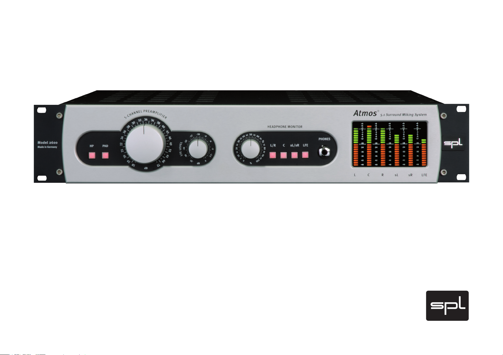
Control Elements
5-Channel Preamplier Control
The central, 5-layer gain control allows for adjusting preamplication values
between 18 and 72 dB. It controls all channels simultaneously.
Switches: HP and PAD
The PAD switch reduces input level by -25 dBu. The HP switch activates a high pass
lter at 70 Hz, e.g. to eliminate subsonic frequencies.
Outputs
For recordings of the preamplied signals recording devices like a multitrack
recorder can be connected either to the XLR or DB 25 outputs.
LFE Level control
The LFE signal is composed from all channels automatically. Frequency is xed at
80 Hz, you can simply set the level with the LFE level control (-32 to 0 dB).
PPM Meters
The PPM meters display the levels at the output of each bus. Values range between
-48 dBu und +9 dBu and are displayed in steps of 3 dB.
A short example: How to use the Atmos
One can describe the work with the Atmos very good with the example of an
orchestral recording.
The main mic array is placed in a central position in front of the orchestra.
We choose a position of 1 to 2 meters behind and at least 4 meters above the
conductor.
As a starting point we recommend to adjust all mic heads in their 0° position (if the
mic capsules can be moved) and to select a hypercardioid polar pattern. Moving
the mic capsules allows for ne adjustments, for example smaller L/R angles result
in larger sound stages of small orchestras.
In general, the same rules apply as with standard miking techniques. So every user
can and should develop his own working practice for individual optimization.
Page 7

7
Frequency range
Mic Out @ 18 dB Gain: 10 Hz-180 kHz (+/-3 dB, Phase –2°)
CMRR 100 Hz 1 kHz 10 kHz
18 dB Gain: -79 dB -79 dB -60 dB
34 dB Gain: -66 dB -66 dB -52 dB
60 dB Gain: -45 dB -45 dB -32 dB
w. Pad -16 dB @ 18 dB Gain: -90 dB -90 dB -79 dB
THD & N 1 kHz 10 kHz
60 dB Gain: 0,22 % 0,24 %
50 dB Gain: 0,07 % 0,07 %
40 dB Gain: 0,022 % 0,023 %
30 dB Gain: 0,007 % 0,007 %
18 dB Gain: 0,002 % 0,0023 %
S/N ratio (A-weighted)
150 Ohm generator, 22 Hz-22 kHz lter, 60 dB Gain@150 Ohm
Mic Out: -66,8 dB
50 dB Gain@all: -77,2 dB
40 dB Gain@all: -85,8 dB
30 dB Gain@all: -93,6 dB
18 dB Gain@all: -96,4 dB
w. PAD -16 dB @ 18 dB Gain: -97,5 dB
Overload resistance +22 dB
Speci cations
Page 8

Atmos Surround Miking System, Model 2600 Manual
Contact
Sound Performance Lab
Sohlweg 80, 41372 Niederkruechten, Germany
Fon +49 (0) 21 63-9 83 40
Fax +49 (0) 21 63-98 34 20
Mail: info@spl.info
Internet: www.spl.info
 Loading...