

Page 1
Manual
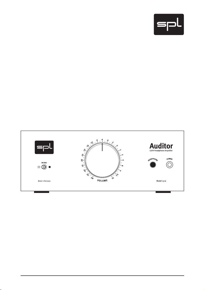
Auditor
Model 2910
120 volts headphone amplifier
Page 2
2
Auditor
Manual Auditor
Model 2910
Version 1.0 – 5/2009
Designer: Wolfgang Neumann
This user‘s guide contains a description of the product. It in no way represents
a guarantee of particular characteristics or results of use. The information in
this document has been carefully compiled and verif ied and, unless other wise
stated or agreed upon, correctly describes the product at the time of packaging
with this document.
Sound Performance Lab (SPL) continuously strives to improve its products and
reser ves the right to modify the product described in this manual at any time wit-
hout prior notice. This document is the property of SPL and may not be copied or
reproduced in any manner, in part or fully, without prior authorization by SPL .
SPL electronics GmbH, Sohlweg 80, 41372 Niederkruechten, Germany
Phone +49 (0)21 63 9 83 40
Fax +49 (0)21 63 98 34 20
E-Mail: info@spl.info
Internet: www.spl.info
CE Declaration of Conformity
Manufacturer: SPL electronic s GmbH, Type of Equipment: Audio
Signal Processor, Product: Auditor, Model 2910, Compliance Engineer:
Wolfgang Neumann
Test Basis: EN50081-1:1992, EN50082-1:19 92, EN60065:1993 , EN61000-3-
3:1995, EN60065:20 02, EN55013:2001, EN55020:20 02, EN61000 -3-2:2000,
73/23 EWG; 93/68 EWG. We herewith declare, that the cons truc tion of the
Auditor, Model 2910, is in compliance with the standards and regulations men-
tioned above.
Notes on Environmental Protection
At the end of its operating life, this product must not be disposed of
with regular household waste but must be returned to a collection
point for the recycling of electrical and electronic equipment. The
“wheelie bin“ symbol on the product, user‘s manual and packaging
indicates that. The materials can be re-used in accordance with their markings.
Throug h re-use, recycling of raw materials, or other forms of recycling of old
produc ts, you are making an important contribution to the protection of our
environment. Your loc al administrative office can advise you of the responsible
waste disposal point.
WEEE Registration: 973 349 88
© 20 09 SPL elect ronics GmbH. All rights reser ved. Names of other companies
and their products are trademark s of their respective owners.
Page 3

Auditor
3
Symbols & Notes ....................................................... 4
Scope of Delivery & Packaging ..................................... 4
Important Security Information ..................................... 5
Hook Up .............................................................. 7
Power Connection, Placement, Before you begin .. . .. .. .. .. .. .. 7
INTRODUCTION ...................................................... 8
The Acoustic Magnifier, 120 Volts Technolog y . .. ... . .. .. .. .. .. .. 8
The End of Ear Fatigue .. .. .. .. .. .. ... . .. .. .. .. .. .. .. ... . .. .. .. .. .. . 9
REAR PANEL .......................................................... 10
Wiring . .. .. .. .. .. ... . .. .. .. .. .. .. .. ... . . .. .. .. .. .. ... . .. .. .. .. .. .. .. 10
Voltage Selector, Power Connector & Fuse, On/Off Switch . .. .. . 11
XLR Sockets, Unbalanced Connections (e. g. RCA, TS Jack) ..... 12
FRONT PANEL ........................................................ 13
Headphone Connection, Recommendations, Warning . . .. .. .. .. 13
CONTROL ELEMENTS ................................................. 14
Mono, Volume .. . .. .. .. .. .. .. ... . .. .. .. .. .. .. .. .... . .. .. .. .. .. ... . .. 14
Protect your Hearing ................................................. 15
Content
Measurements ....................................................... 15
Frequency Response . . .. .. .. .. .. .. .. .. ... . .. .. .. .. .. .. .. ... . .. .. .. 15
Phase Response ... . .. .. .. .. .. .. .. ... . .. .. .. .. .. .. .. ... . .. .. .. .. .. . 1 6
THD vs. Frequency . .. .. .. .. .. .. .. .. ... . .. .. .. .. .. .. .. ... . .. .. .. .. .. 16
Specifications ........................................................ 17
Guarantee & Product Registration .................................. 18
Page 4
4
Auditor
Symbols and Notes
IN THIS MANUAL A LIGHTNING SYMBOL WITHIN A TRIANGLE WARNS
YOU ABOUT THE POTENTIAL FOR DANGEROUS ELECTRICAL SHOCKS
– WHICH CAN AL SO OCCUR EVEN AFTER THE MACHINE HAS BEEN
DISCONNECTED FROM A POWER SOURCE.
AN EXCL AMATION MARK (!) WITHIN A TRIANGLE IS INTENDED TO MAKE
YOU AWARE OF IMPORTANT OPERATIONAL ADVICE AND/OR WARNINGS
THAT MUST BE FOLLOWED. BE ESPECIALLY ATTENTIVE TO THESE AND
ALWAYS FOLLOW THE ADVICE THEY GIVE.
The symbol of a lamp directs your attention to explanations of important functions or applications.
Attention
Do not attempt any alterations to this machine without the approval
or super vision of SPL electronics GmbH. Doing so could nullify completely any and all of your warranty/guarantee rights and claims to
user support.
Scope of Delivery and Packaging
• Auditor, Model 2910
• Power cord
• Guarantee card
• This manual
Please keep the original packaging. In case of a ser vice procedure the
original packaging ensures a safe transport. It also serves as a safe
packaging for your own transports if you do not use special transportation cases.
Page 5

Auditor
5
Important Security Information
Please note and retain this manual. Carefully read and follow all of the
safety and operating instructions before you use the machine. Be doubly careful to follow all warnings and special safety instructions noted
in this manual and on the unit.
Connections: Only use the connections as described. Other connections can lead to health risks and equipment damage.
Water and humidity: Do not use this machine anywhere near water (for
example near a wash basin or bath, in a damp cellar, near swimming
pools, or the like). In such cases there is an extremely high risk of fatal
electrical shocks!
Insertion of foreign objects or fluids: Never allow a foreign object
through any of the machine‘s chassis openings. You can easily come
into contact with dangerous voltage or cause a damaging short circuit.
never allow any fluids to be spilled or sprayed on the machine. Such actions can lead to dangerous electrical shocks or fire!
Opening the Unit: Do not open the machine housing, as there is great
risk you will damage the machine, or – even after being disconnected –
you may receive a dangerous electrical shock!
Electrical power: Run this machine only from sources which can provide
proper power at the prescribed rating. When in doubt about a source,
contact your dealer or a professional electrician. To be sure you have
isolated the machine, do so by disconnecting the power cord from your
wall connection. Be sure that the power cord plug is always accessible.
When not using the machine for a longer period, make sure to unplug it
from your wall power socket.
Power cord protection: Make sure that your power cord is arranged to
avoid being stepped on or any kind of crimping and damage related
to such event. Do not allow any equipment or furniture to crimp this
power cord.
Power connection overloads: Avoid any kind of overload in connections to wall sockets, extension or splitter power cords. Always keep
manufacturer warnings and instructions in mind. Overloads create fire
hazards and risk of dangerous shocks!
Lightning: Before thunderstorms or other severe weather, disconnect
the machine from wall power (but to avoid life threatening lightning
strikes, not during a storm). Similarly, before any severe weather, disconnect ALL the power connections of other machines and antenna and
phone/network cables which may be interconnected so that no lightning damage or overload results from such secondar y connections.
Page 6

6
Auditor
Important Security Information
Air circulation: Chassis openings offer ventilation and serve to protect
the machine from overheating. Never cover or otherwise close off these
openings. never place the machine on a soft surface (carpet, sofa, etc.).
Make sure to provide for a mounting space of 4-5 cm/2 inches to the
sides of the unit when mounting the unit in racks or cabinets.
Controls and switches: Operate the controls and switches only as
described in the manual. Incorrect adjustments outside safe parameters can lead to damage and unnecessary repair costs. Never use
the switches or level controls to effect excessive or extreme changes.
Repairs: Unplug the unit and immediately contact a qualified technician when you think repairs are needed – or when moisture or foreign objects may accidentally have gotten in to the housing, or in
cases when the machine may have fallen and shows any sign of having been damaged. This also applies to any situation in which the unit
has not been subjected to any of these unusual circumstances but
still is not functioning normally or its performance is substantially altered.
In cases of damage to the power cord or its plug, first consider turning
off the main circuit breaker before unplugging the power cord.
Replacement/substitute parts: Be sure that any ser vice technician
uses original replacement parts or those with identical specifications
as the originals. Incorrectly substituted parts can lead to fire, electrical
shock, or other dangers, including further equipment damage.
Safety inspection: Be sure always to ask a service technician to conduct a thorough safety check and ensure that the state of the repaired
machine is in all respects up to factory standards.
Cleaning: In cleaning, do not use any solvents, as these can damage
the chassis finish. Use a clean, dry cloth (if necessary, with an acid-free
cleaning oil). Disconnect the machine from your power source before
cleaning.
Page 7

Auditor
7
Power Connection
Be very careful to check that the rear chassis power selection switch
is set to the correct local line voltage position before using the unit
(230 V position: 220-240 V/50 Hz, 115 V position: 110-120 V/60 Hz)!
When in doubt about a source, contact your dealer or a professional
electrician.
Before connecting any equipment make sure that any machine to be
connected is turned off. Follow all safety instructions on page 5 and 6.
Placement
Place the unit on a level and stable surface. The unit’s enclosure is EMCsafe and effectively shielded against HF interference. Nonetheless, you
should carefully consider where you place the unit to avoid electrical
disturbances. It should be positioned so that you can easily reach it,
but there are other considerations. Try not to place it near heat sources
or in direct sunlight, and avoid exposure to vibrations, dust, heat, cold
or moisture. It should also be kept away from transformers, motors,
power amplifiers and digital processors. Always ensure sufficient air
circulation by keeping a distance of 4-5 cm/2 inches to the top and
sides of the unit.
Hook Up
Before You Begin
Make sure that the POWER SOAK control is turned fully left before you
power up the unit. Now control volume. Note that too high levels can
damage connected units and hearing!
Page 8

8
Auditor
Introduction
There is more than meets the eye in working with headphones. A reason for this surely lies in that modern audio production often necessitates decentralized processes. In turn, production phases following
such plans more often take place in acoustically questionable rooms.
In such circumstances, a mix might occur in an acoustically deficient
ambiance (for example, in an extremely modal room), and employing
headphones then begins to make sense when a successful mix would
otherwise turn out to be impossible.
Acoustic Magnifier
But also when working with full range monitors in the studio, headphone monitoring is an extremely important alternative to loudspeaker
monitoring: analytical monitoring via headphones offers a very high
precision to observe details. Headphone monitoring is like working with an acoustic magnifier, excluding external room influences.
Working with the magnifier effect of headphones has the advantage of
safely hearing clicks or similar defects and helps in fine tuning crossfades or to judge tonal problems in individual tracks.
120 Volts Technology
The Auditor is our interpretation of a high-end headphone amplifier.
We strictly followed a purist approach to achieve the highest sound
quality. The alternative to the Auditor is the full-featured headphone
monitoring amplifier Phonitor. Based upon our unique 120 volts design
as well, the Phonitor transfers the essential ambient parameters of
loudspeaker monitoring to the headphone monitoring.
The basis for such high-end developments is our proved 120 volts reference technology. Core elements are the handmade SPL SUPRA opamps running on 120 volts – it corresponds to approximately twice that
of most modern analog audio semiconductor technologies. Through
such 120 volts circuitry and processing we reach performance levels far
beyond conventional designs in dynamic range and distortion levels,
and such technical specifications exceed all known analog or digital
standards.
Page 9

Auditor
9
The End of Ear Fatigue
With headphones, ear fatigue can begin relatively soon, and there are
several causes.
First, some cans themselves may not be that comfortable to wear...
Moreover, a standard headphone amplifier is of ten an additional important reason for premature ear fatigue. Almost without exception,
present-day headphone amplifiers employ comparatively undemanding IC’s. In the best cases they might work with symmetrical voltages of
+/-15 V to +/-18 V, and in less favorable cases, with only a simple supply
of 9 or 12 V from cheaper external “wall-wart“ power supplies.
But the voltage level acts in circuitry much like the cubic inch capacity
to the productive power of a combustion engine: Cubic inch capacity is
replaceable with nothing but more cubic inch capacity – and in the productive power of electronics, voltage level functions similarly.
For some years, now, SPL has addressed this issue in all of its mastering product series through its own specifically developed 120 volt technology. Consoles and signal processors of the SPL Mastering Series
appear as central elements in installations of today’s most renowned
mastering houses (e. g. Bob Ludwig’s Gateway Mastering & DVD in the
USA, Simon Heyworth’s Super Audio Mastering in Great Britain or the
Galaxy Studios in Belgium). This 120 volt technology is based on discrete operation amplifiers from SPL’s own production, developed and
perfected over many years by SPL’s co-founder and chief developer,
Wolfgang Neumann. The SUPRA OPs have a signal to noise ratio of
116 dB and of fer a 34 dB headroom – that yields an unequalled 150 dB
dynamic range.
The musical result is not to be mistaken: Regardless of the monitoring means, regardless of how loud you monitor – the Auditor always
remains a distant, impartial factor unaffected when used to capacity
and beyond being overloaded. The phase stability is always perfect, its
THD next to immeasurable. The SUPRA OPs cannot be stressed in the
most stressful circumstances, and for precisely this reason its musical
sound is always relaxed and spacious. All frequencies are reproduced
in balance, basses are stable and tight, mids are clear and differentiated and highs remain transparent and sof t.
Such supreme and heretofore unreachable neutrality in audio reproduction is the direct consequence of our technical approach and basis
in 120 volt technology: Possible disturbances from such as noise or
distortion are so slight that we even arrive at the boundaries of the
best measuring equipment, and what remains is quite simply unaltered
musical sound.
Introduction
Page 10

10
Auditor
Rear Panel/Connections
Make sure that the voltage switch setting
reflects the correct local power line voltage.
Input & output
right channel
The Auditor can be fed from any stereo signal path via its
rear panel XLR sockets. Headphone connection on the front panel.
Input & output
left channel
Power supply
connection
Power
switch
Wiring
Page 11

Auditor
11
Sockets & Switches
Rear Panel/Connections
Voltage
The rear panel voltage selector switch serves to let the user switch to
the local line voltage standard.
IMPORTANT ADVICE: Before you use the Auditor, make sure
that this switch setting reflects the correct local power
line voltage (115 V position: 110-120 volts/6o Hz, 230 V
position: 220-240 volts/50 Hz).
Power Connection and Fuse
Connect the included p ower cord to the rear power supply socket.
Transformer, power cord and case connection conform to VDE, UL
and CSA requirements. The power fuse is installed behind the clack
right to the power connector. Power fuse ratings are 200 mA slow blow
220-240
(
volts) or 400 m A slow blow (
110-120
volts).
On/Off Switch
The rear panel On/Off switch activates the unit, confirmed by the lighted POWER LED on the front panel.
IMPORTANT ADVICE: Switch on the unit only after you have turned the
Volume control fully left, and wait to set your desired volume level
until the unit is powered on. Neglecting this can damage either or both
your ears and your headphones!
Page 12

12
Auditor
Rear Panel/Connections
Input
Output
balanced
unbalanced
balanced
unbalanced
1= GND
2=hot (+)
3=cold (-)
1
2
3
1
2
3
1
2
3
1
2
3
XLR Connections
Switch off the unit before you begin the process of making the first
or any subsequent connections (rear panel On/Off switch). Neglecting
this can damage either or both your ears and your headphones!
Connect the monitoring signal to the left and right channel XLR input
sockets. Both XLR outputs transmit the monitoring signal unaltered
so that no additional monitoring output is needed for insertion of the
Auditor. Input and output stages are electronically balanced. They ensure high common mode rejection and drive long cable connections
(depending on cable capacities and following input stages).
Unbalanced Connections (e. g. RCA, TS Jack)
You can establish unbalanced connections easily and without adaptors – for example from CD-Players with RCA outputs or to (HiFi) power
amplifiers with RCA inputs. It is important to pay attention to the correct polarity of the three XLR wires. The diagram shows the pin wiring of all XLR sockets as well as the correct polarit y for unbalanced
connections:
Connections to RCA and TS Jack inputs or outputs are always unbalanced. Connections to TRS inputs or outputs may be balanced or unbalanced. In any case we recommend to use readily configured cables
from XLR to the respective RC A or TS/TRS connector to dispense with
adaptors. Ask your dealer for configured cables. With the diagram
above any audio expert can ensure to select or configure the right cables for connections from the Auditor to any other device.
Page 13

Auditor
13
Front Panel/Connection
Headphone Connection
You can use all dynamic headphones from 20-600 ohms (connection
impedance). Connect your headphones to the standard 1/4" (TRS)
stereo jack plug on the front panel. Make sure that the plug is firmly
seated for a solid connection.
Pin wiring TRS jack: Tip=left channel, ring=right channel, sleeve=ground.
Recommendations
Unplug the headphone when you switch off the Auditor. Otherwise
discharging residual voltages can cause beeping sounds. We did not
add a circuitry to avoid that phenomenon because it would compromise sound quality.
Reduce volume level before you remove or plug in the headphone (or
when switching headphones). This excludes louder clicks and pops
reaching the ear. In addition, this can avoid unpleasant surprise that
follows when a headphone’s lower impedance suddenly reproduces an
otherwise acceptable Auditor volume setting of a first headphone at a
much higher – even painful – level.
Warning
NEVER plug in a mono 1/4" jack (TS) to the headphone output. The use
of a mono 1/4" will lead to a short-circuit that will destroy the final
amplifier stage! Standard headphone connectors always have stereo
plugs, and thus a correct connection will be assured when you only
connect headphones directly. Double check that you use stereo 1/4"
TRS plugs when you connect headphones via patchbays or extension
cables etc.
Page 14

14
Auditor
Control Elements
V
O
L
U
M
E
Usually already a short contemplative moment should be suf ficient to
get a general idea of the Auditor ’s user interface and it’s control elements. Once more the advantages of a consequently purist design approach are becoming obvious – writing and reading the actual operational instructions just takes two beats.
Mono
The MONO switch creates a sum of the left and right channel, so you
can listen to stereo sources also in mono. You can also listen to a mono
source on both monitoring channels. The MONO switch is of course
also important and useful to examine the mono compatibility of a mix.
Phase alterations or reversions that may not be too obvious in the stereo panorama can be detected more clearly in a mono sum – in extreme
cases they lead to cancellations.
Volume
The VOLUME level control allows you to increase or decrease the sig-
nal level at the headphone output from between +10dB down to
-80dB.
To this end we employ a high-grade ALPS RK27 poten-
tiometer. It distinguishes itself through a high head-
room, ver y low tolerance and excellent handling
that on the one hand offers sufficient resistance
while, on the other, avoids stickiness.
The VOLUME control is calibrated in a relative dB
scale that references the input level. The 0dB set-
ting is around the two o’clock position, where the
input signal is led to the output with an unaltered
level (unity gain).
If a 600 Ohms headphone is connected, a 0 dB VOLUME
control setting results in ca. 80 dB sound pressure level,
measured at a distance of 3 cm from a headphone trans-
ducer. With a stereo signal the sound pressure level is then at ca.
83 dB – a common reference monitoring level.
Page 15

Auditor
15
Protect Your Hearing
Audio Precision 05/04/09 12:33:42Auditor Model 2910
-3
+3
-2
-1
+0
+1
+2
d
B
u
10 200k20 50 100 200 500 1k 2k 5k 10k 20k 50k
Hz
Always reduce volume before you put on headphones or before you remove or plug in the headphone. This excludes louder clicks and pops
reaching the ear. In addition, this can avoid unpleasant surprise that
follows when a headphone’s lower impedance suddenly reproduces a
much higher – even painful – level.
Always take care of your hearing when monitoring – especially with
headphones. Reduce volume all the time as far as possible and expose
your hearing to higher volumes only for short periods. As an orientation: German laws oblige ear protection in the professional area if the
hearing is exposed to more than 85 dB sound pressure level – this level
can already damage the hearing in the long term.
The Auditor can produce sound pressure levels that may be dangerous
for your hearing because the large impedance scale of headphones
requires a large performance range. Always regulate volume by starting from the zero position especially when you start working or switch
headphones.
Measurements
Frequency Resp onse Input/Headphone Output, Lef t and Right Channel
Measuring output and input 600 Ohm, Volume control Auditor 0 dB:
‹10 Hz to ›200 kHz (-3dB).
The large Frequency response range excludes that the frequency spectrum is limited at any point. Transmission of formants and octaves of an
instrument’s sounds can not be narrowed.
Page 16

16
Auditor
Measurements
Audio Precision 05/04/09 15:04:58 THD+N vs FREQUENCY
0.00001
5
0.0001
0.001
0.01
0.1
1
%
2k 20k4k 6k 8k 10k 12k 14k 16k 18k
Hz
Audio Precision 05/14/08 13:23:13Auditor Phase/FC
-10
+10
-8
-6
-4
-2
+0
+2
+4
+6
+8
d
B
u
-150
+150
-100
-50
+0
+50
+100
d
e
g
20 100k50 100 200 500 1k 2k 5k 10k 20k 50k
Hz
Phase Response Input vs. Output, Left and Right Channel
Measuring output and input 600 Ohm, Volume control Auditor 0 dB.
This measurement shows the minimum deviation of phase in the upper
frequency range. Phase response describes the time difference between input and output signal – the less, the better. The extremely tight
phase response up to 50 kHz excludes any audible effects.
THD vs. Frequency
Measuring output and input 600 Ohm, Volume control Auditor 0 dB.
THD vs. frequency range from 10 to 20 kHz at 0 dB over both channels.
The values are extremely low around 0.001% throughout the whole
range; even in long sessions this ensures listening without ear fatigue.
Page 17

Auditor
17
Audio
Frequency response: ‹5 Hz to ›200 kHz ( -3 dB)
CMRR: -80 dBu
(@1 kHz, 0dBu input level and unity gain)
Crosstalk @ 1 kHz: -84 dB
THD @ 1 kHz: 0,001 %
(@1 kHz, 0dBu input level and unity gain)
Noise (A-weighted): -97 dBu
Dynamic range: 129 dB
(@ connec tion with 600 Ω impedance)
Inputs (XLR sockets, electronically balanced)
Impedance: ca. 20 kΩ balanced
ca. 10 kΩ unbalanced
Maximum Input Level: +24 dBu
Outputs
XLR connections: Input thru, electronically balanced
Headphone output: 6,35 mm stereo 1/4" TRS connection
Pin wiring: tip=lef t, ring=right, shaft=GND
Min. Impedance connected:
Power Amplier
Max. Output Performance: 1,7 W (+32,2 dBm)
@ 1 kHz and 600 Ω connection
360 mW (+25,6 dBm)
@ 1 kHz and 30 Ω connection
9 Ω
Specications
Power Supply
Features: Toroidal transformer with voltage selector
Voltages: 230 V AC, 50 Hz / 115 V AC, 60 Hz
Fuses (slow blow): 200-240 V AC: T 200 mA
100-120 V AC: T 400 m A
Power consumption: max. 5,6 W/7,9 VA/0,03 A
Dimensions & Weight
Height x Width x Depth: 95 x 210 x 315 mm
Depth with Volume knob: 335 mm
Height with lif ted feet: 127 mm
Weight: 2.65 kg/5,84 lbs
Note: 0 dBu = 0,775 V. Specications are subject to change without notice.
Page 18

Guarantee & Product Registration
Please note the terms on the guarantee card enclosed in the package.
Direct SPL product support requires product registration. Please fill
out the guarantee card in printed letters and send it directly to SPL. Or
use the online registration form that may be reached at www.spl.info.
18
Auditor
 Loading...