

Page 1
Manual
7
5
3
1
0
3
5
30
50
70
100
VU
5
3
1
VU
20
1 0
0
%
M
I
C
G
A
I
N
S
-
R
E
D
U
C
T
I
O
N
I
N
S
T
R
U
M
E
N
T
S
-
D
E
T
E
C
T
A
D
-
O
V
L
1
3
1
4
1
5
1
6
1
8
2
0
2
2
2
4
2
6
2
8
3
0
3
3
3
6
3
9
4
2
4
5
5
2
6
1
6
8
I
N
S
T
R
.
G
A
I
N
L
I
N
E
G
A
I
N
R
A
T
I
O
A
T
T
A
C
K
L
M
F
M
H
F
L
M
F
–
/
+
M
H
F
–
/
+
A
I
R
B
A
N
D
T
U
B
E
S
A
T
U
R
A
T
I
O
N
IN S T R.
LIN E I N
TUB E
+1 5 dB
ON ON
MUTE
EQ PRE
C OM P .
EQ / T UB EC OM P .
EXTERNAL INPUTS
DE-ES.
AUTO
48 V PAD
Recording Channel
Ø
M
A
K
E
-
U
P
R
E
L
E
A
S
E
O
U
T
P
U
T
Sound Performance Lab Made in Germany
ON
0
-
1
-
2
-
3
-
4
-
6
-
9
-
1
1
-
1
2
2
1
1
6
1
1
6
0
-
5
-
9
-
1
6
-
2
2
-
3
0
-
3
8
-
4
6
-
5
4
-
5
8
1
.
2
1
.
4
1
.
7
2
.
0
2
.
3
2
.
7
3
.
0
3
.
6
5
.
0
1
6
∞
0
1
0
2
0
3
0
4
0
5
0
6
0
7
0
8
0
9
0
1
0
0
-
2
0
-
1
3
-
7
.
5
-
4
.
5
-
2
0
1
.
5
3
4
5
5
.
5
0
.
1
0
.
2
0
.
4
1
.
0
2
.
5
7
.
0
1
6
4
0
1
3
0
5
3
0
1
0
0
0
0
.
0
3
0
.
0
5
0
.
0
9
0
.
1
5
0
.
2
5
0
.
4
0
.
6
5
1
.
0
1
.
3
1
.
8
2
.
0
0
0
.
5
1
2
3
4
5
6
7
8
9
1
0
1
2
1
4
1
6
1
9
2
0
-
1
2
-
1
0
-
5
-
2
.
5
0
2
.
5
5
7
.
5
1
0
1
2
-
1
2
-
1
0
-
5
-
2
.
5
0
2
.
5
5
7
.
5
1
0
1
2
-
1
0
-
8
-
6
-
4
-
2
0
2
4
6
8
1
0
6
8
0
8
2
0
1
k
0
1
k
5
2
k
7
3
k
4
4
k
5
6
k
5
1
0
k
1
3
k
1
5
k
3
0
4
0
5
0
8
0
1
2
5
1
6
0
2
0
0
3
0
0
5
0
0
6
4
0
7
0
0
Model 2800
GRVU VU PPM 0 dB - 1 0 dB
T
H
R
E
S
H
O
L
D
Frontliner
6
8
1
1
1
4
1
7
1
9
2
1
2
3
2
5
2
6
2
7
2
9
3
2
3
5
3
7
3
9
4
1
4
2
4
3
-
2
0
-
1
8
-
1
2
-
9
0
3
9
1
0
dB 1 :x dB dB
dB dBHz
Hz %
ms s
dB dB
dB
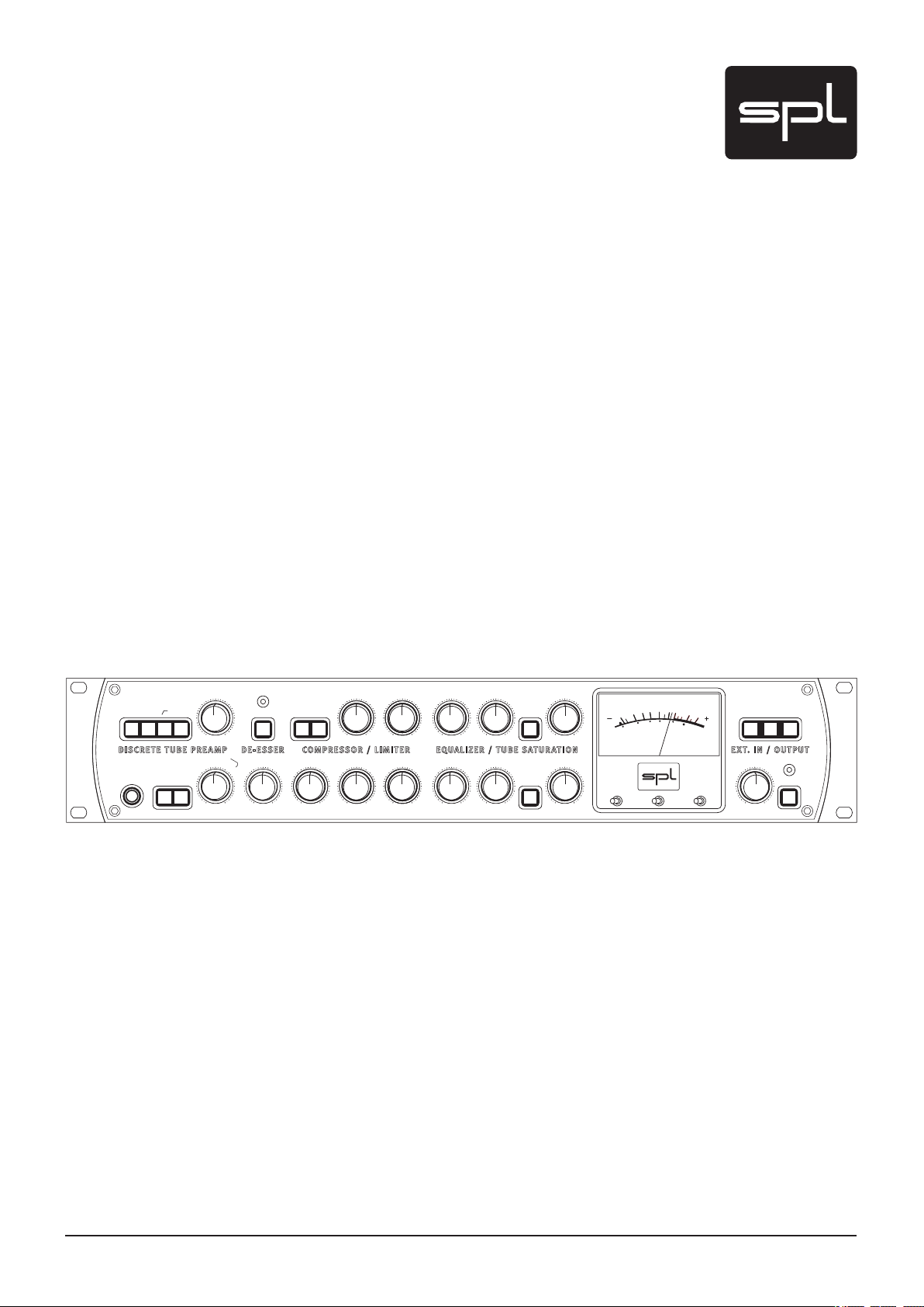
Frontliner
Model 2800
Recording channel with separate module inputs and outputs
Page 2

2
Frontliner
Manual Frontliner, Model 2800
Version 1.0– 6/2009
Designer: Jens Gronwald
This manual contains a description of the product. It in no way represents a guarantee of
particular characteristics or results of use. The information in this document has been carefully compiled and veried and, unless otherwise stated or agreed upon, correctly describes
the product at the time of packaging with this document.
Sound Performance Lab (SPL) continuously strives to improve its products and reserves the
right to modify the product described in this manual at any time without prior notice. This
document is the property of SPL and may not be copied or reproduced in any manner, in part
or fully, without prior authorization by SPL.
SPL electronics GmbH
Sohlweg 80, 41372 Niederkruechten, Germany
Phone +49 (0)2163 983 40
Fax +49 (0)2163 983 420
E-Mail: info@spl.info
Internet: www.spl.info
The construction of the Frontliner, Model 2800, is in compliance with the standards and regulations of the European Community.
Notes on Environmental Protection
At the end of its operating life, this product must not be disposed of with regular
household waste but must be returned to a collection point for the recycling of
electrical and electronic equipment. The wheelie bin symbol on the product,
user‘s manual and packaging indicates that. The materials can be re-used in
accordance with their markings. Through re-use, recycling of raw materials, or
other forms of recycling of old products, you are making an important contribution to the
protection of our environment. Your local administrative ofce can advise you of the responsible waste disposal point.
WEEE Registration: 973 349 88
© 2009 SPL electronics GmbH. All rights reserved. Names of other companies and their
products are trademarks of their respective owners.
Page 3

3
Frontliner
Symbols & Notes ............................................................................... 4
Scope of Delivery & Packaging ................................................................ 4
Important Security Information ............................................................... 4
Hook Up .......................................................................................... 5
Introduction ..................................................................................... 6
The Frontliner concept, Analog plug-ins ................................................... 6
Special technical features, Options ........................................................ 7
REAR PANEL ..................................................................................... 8
Standard wiring channel strip .............................................................. 8
Wiring examples: live and studio ............................................................ 9
Wiring examples: group of modules, Inserts ............................................. 1 0
Rear panel/sockets ........................................................................ 1 0
Signal connections, TRS socket, XLR sockets,
Balanced connections, Unbalanced connections ......................................... 11
Separate inputs and outputs, Preamplier: MIC IN,
Preamplier: LINE IN, Preamplier: OUT, De-Esser: IN and OUT ......................... 1 2
Compressor: IN and OUT, Equalizer/Tube Sat.: IN and OUT,
Main Outs OUT1 and OUT 2, AD Input 2, Power connection and fuses ................... 13
Rear Panel/Switches ....................................................................... 1 4
Voltage selector, Power switch, 48 V phantom power/rear switches, GND Lift .......... 14
CONTROL ELEMENTS ........................................................................... 1 5
Preamplier ................................................................................. 1 5
MIC GAIN, MIC GAIN adjustments, 48 V, Activating phantom power ..................... 15
Phase reverse, High-pass lter, PAD, Instrument input ................................... 16
LINE GAIN/INSTR. GAIN, LINE GAIN and INSTR. GAIN adjustments,
INSTR. LINE IN, TUBE +15 dB ................................................................ 17
De-Esser .................................................................................... 1 8
ON, S-REDUCTION, SPL De-Esser technology ............................................. 18
Compressor/Limiter ........................................................................ 19
ON, THRESHOLD, RATIO, ATTACK .......................................................... 19
ATTACK with cruise control: Auto Mode, RELEASE,
RELEASE with cruise control: AUTO-Mode, MAKE UP ..................................... 20
Equalizer/Tube Saturation ................................................................. 21
ON, EQ PRE COMP., MHF (mid-/hi lter), MHF -/+ (cut/boost MHF)
LMF (low/Mid lter), LMF -/+ (cut/boost LMF),
AIR BAND, TUBE SATURATION .............................................................. 22
VU-Meter .................................................................................... 23
VU-Meter, VU/GR switch, 0 dB/-10 dB switch, VU/PPM switch ............................ 23
Output ....................................................................................... 24
OUTPUT, AD OVL-LED, MUTE switch ...................................................... 24
External Inputs ............................................................................. 25
Excluding a single module, Excluding a group of two or three modules, Ungroup ...... 25
Determining inserts, Key lock, Keys and switches ......................................... 26
2 1
Content
Options .......................................................................................... 27
24/96 A/D converter model 2376, Information on I/O transformers ... . . .. .. .. .. . .. .. .. . 27
Specications ................................................................................... 28
Copy master: recall settings ................................................................... 30
Block diagrams .................................................................................. 31
Table Switch Logic .............................................................................. 33
Page 4
4
Frontliner
Symbole and Notes
IN THIS MANUAL A LIGHTNING SYMBOL WITHIN A TRIANGLE WARNS YOU ABOUT THE
POTENTIAL FOR DANGEROUS ELECTRICAL SHOCKS – WHICH CAN ALSO OCCUR EVEN AFTER
THE MACHINE HAS BEEN DISCONNECTED FROM A POWER SOURCE.
AN EXCLAMATION MARK (!) WITHIN A TRIANGLE IS INTENDED TO MAKE YOU AWARE OF
IMPORTANT OPERATIONAL ADVICE AND/OR WARNINGS THAT MUST BE FOLLOWED. BE
ESPECIALLY ATTENTIVE TO THESE AND ALWAYS FOLLOW THE ADVICE THEY GIVE.
The symbol of a lamp directs your attention to explanations of important functions or applications.
Attention: Do not attempt any alterations to this machine without the approval or supervision
of SPL electronics GmbH. Doing so could nullif y completely any and all of your warranty/guarantee rights and claims to user support.
Scope of Delivery & Packaging
The scope of delivery comprises the Cabulator, the external power supply, the guarantee card
and this manual.
Please keep the original packaging. In case of a service procedure the original packaging
ensures a safe transport. It also serves as a safe packaging for your own transports if you do
not use special transportation cases.
Important Security Information
Please note and retain this manual. Carefully read and follow all of the safety and operating
instructions before you use the machine. Be doubly careful to follow all warnings and special
safety instructions noted in this manual and on the unit.
Connections: Only use the connections as described. Other connections can lead to health
risks and equipment damage.
Water and humidity: Do not use this machine anywhere near water (for example near a wash
basin or bath, in a damp cellar, near swimming pools, or the like). In such cases there is an
extremely high risk of fatal electrical shocks!
Insertion of foreign objects or uids: Never allow a foreign object through any of the
machine‘s chassis openings. You can easily come into contact with dangerous voltage or
cause a damaging short circuit. Never allow any uids to be spilled or sprayed on the machine.
Such actions can lead to dangerous electrical shocks or re!
Opening the unit: Do not open the machine housing, as there is great risk you will damage the
machine, or – even after being disconnected – you may receive a dangerous electrical shock!
Electrical power: Run this machine only from power sources which can provide proper power
in the range from 100 to 250 volts. When in doubt about a source, contact your dealer or a
professional electrician. To be sure you have isolated the machine, do so by disconnecting all
power and signal connections. Be sure that the power supply plug is always accessible. When
not using the machine for a longer period, make sure to unplug it from your wall power socket
and from the guitar amp.
Cord protection: Make sure that your power and guitar amplier signal cords are arranged
to avoid being stepped on or any kind of crimping and damage related to such event. Do not
allow any equipment or furniture to crimp the cords.
Power connection overloads: Avoid any kind of overload in connections to wall sockets,
extension or splitter power cords, or to signal inputs. Always keep manufacturer warnings
and instructions in mind. Overloads create re hazards and risk of dangerous shocks! >
Page 5

5
Frontliner
Lightning: Before thunderstorms or other severe weather, disconnect the machine from wall
power (but to avoid life threatening lightning strikes, not during a storm). Similarly, before
any severe weather, disconnect all the power connections of other machines and antenna and
phone/network cables which may be interconnected so that no lightning damage or overload
results from such secondary connections.
Air circulation: Chassis openings offer ventilation and serve to protect the machine from overheating. Never cover or otherwise close off these openings. Never place the machine on a soft
surface (carpet, sofa, etc.). Make sure to provide for a mounting space of 4-5 cm/2 inches to
the sides and top of the unit when mounting the unit in racks or on cabinets.
Controls and switches: Operate the controls and switches only as described in the manual.
Incorrect adjustments outside safe parameters can lead to damage and unnecessary repair
costs. Never use the switches or level controls to effect excessive or extreme changes.
Repairs: Unplug the unit from all power and signal connections and immediately contact a qualied technician when you think repairs are needed – or when moisture or foreign objects may accidentally have gotten in to the housing, or in cases when the machine may have fallen and shows
any sign of having been damaged. This also applies to any situation in which the unit has not
been subjected to any of these unusual circumstances but still is not functioning normally or its
performance is substantially altered.
In cases of damage to the power supply and cord, rst consider turning off the main circuit
breaker before unplugging the power cord.
Replacement/substitute parts: Be sure that any ser vice technician uses original replacement
parts or those with identical specications as the originals. Incorrectly substituted parts can
lead to re, electrical shock, or other dangers, including further equipment damage.
Important Security Information
Safety inspection: Be sure always to ask a service technician to conduct a thorough safety
check and ensure that the state of the repaired machine is in all respects up to factor y standards.
Cleaning: In cleaning, do not use any solvents, as these can damage the chassis nish. Use
a clean, dry cloth (if necessary, with an acid-free cleaning oil). Disconnect the machine from
your power source before cleaning.
Be very careful to check that the rear chassis power selection switch is set to the correct
local line voltage position before using the unit (230 V position: 220-240 V/50 Hz, 115 V position: 110-120 V/60 Hz)! When in doubt about a source, contact your dealer or a professional
electrician.
Before connecting any equipment make sure that any machine to be connected is turned off.
Follow all safety instructions on pages 4 and 5 and read further information on connections
on pages 8, 9 an 10.
Place the unit on a level and stable surface. The unit’s enclosure is EMC-safe and effectively
shielded against HF interference. Nonetheless, you should carefully consider where you place
the unit to avoid electrical disturbances. It should be positioned so that you can easily reach
it, but there are other considerations. Try not to place it near heat sources or in direct sunlight,
and avoid exposure to vibrations, dust, heat, cold or moisture. It should also be kept away
from transformers, motors, power ampliers and digital processors. Always ensure sufcient
air circulation by keeping a distance of 4-5 cm/2 inches to the sides and top of the unit.
Hook Up
Page 6

6
Frontliner
Introduction
Our preceding recording channels Track One and Channel One have already been
successful units by combining fast and easy operation with high processing quality. These
channel strips particularly benefit from previous developments for single processors: the
DynaMaxx compressor/limiter delivered the essentials for the respective channel strip
stage, the unique SPL De-Esser is also available as a single, dual-channel unit – and the
preamplifier modules were also derived from existing products.
The development of new units in the last years inevitably evoked the wish to conceive a
new channel strip which would benefit from our latest achievements.
Now the Frontliner comprises the same discrete, hybrid semiconductor/tube preamplifier design like the GoldMike MK2. The compressor module is based upon the Kultube
providing a full set of classic controls. We also integrated the Kultube's highlight, a signaldependent automation of attack and release parameters which can still be influenced
manually – with this option, manual and automatic control can be merged to always f ind
the best settings.
The EQ section provides two semi-parametric filters for low and mid band as well as a bell
filter delivering a silky and smooth top end. This filter set offers a perfect frequency first
aid kit and is rounded off with a Tube Saturation control.
In contrast to semiconductors, a tube does not clip from a certain level, but approaches its
limits by increasingly producing harmonic distortions. The sound effects from saturating
a tube can often be used to improve the audio signal. The sound results resemble tape
saturation effects and increase the density and perceived energy in a very pleasant way.
The Frontliner concept
The Frontliner comprises a hybrid semiconductor/tube preamplifier with microphone,
line and instrument input, a de-esser, a compressor/limiter and an EQ section with tube
saturation stage. In addition to its primary function as a recording channel with all tools
onboard to process a signal prior to storing, its modules can also serve for high-end
analog processing during mixing.
The enumeration of the Frontliner’s modules also makes clear that the task of a channel
strip is relatively complex. There is not one specialized device for one job, but a unit that
combines a lot of technology for the preamplification and processing of audio signals. That
is why especially the Frontliner benefits very much from SPL’s innovations for targeted,
efficient work. The SPL De-Esser, for example, performs a highly complex processing, but
can simply be adjusted with one single knob.
The straight and clear front panel design also suppor ts fast and safe operation.
Analog plug-ins
In the last years we have been busy with modular concepts. One result is the RackPack
series: a RackPack frame hosts up to eight 3U high modules for free placement and (inter-)
connection.
But we have also transferred the modular idea to the Frontliner. Each Frontliner module
disposes of its own inputs and outputs. Sophisticated switching options allow to integrate Frontliner’s modules into a studio environment as if they were stand-alone devices.
You can also group modules in any combination and you can determine inserts at each
module’s input.
If you imagine the Frontliner modules as analog plug-ins, the additional value suddenly
becomes apparent: this channel strip also is a versatile analog processing station. With
one single unit, especially DAW based studios benefit from a first-class recording frontend and have access to high end analog processors for the main signal processing tasks.
Page 7

7
Frontliner
Special technical features
• Three separate, individually optimized inputs for microphones, line signals and instruments.
• Discrete semiconductor/tube hybrid preamplif ier to combine the advantages – high
dynamic range and low noise operation of semiconductors with the musical qualities of
tube sounds (appealing top end, beautiful spacial impression). Discrete construction is
based upon single transistors instead of integrated circuits (ICs) from industrial production
and ensures a higher level of optimization.
• 250 volts tube circuits in the preamplifier and for tube saturation stages.
• High-grade operational amplifiers from Burr-Brown at critical positions.
• The SPL De-Esser applies the method of phase cancellation for reducing sibilants. This
innovative approach works much more neutral than traditional compression methods – a
unique method for unobtrusive results and extremely fast operation.
• The compressor is operated by SPL’s double VCA drive circuitry. A differential stage elimi-
nates side effects and the half load per VCA dramatically reduces THD.
• The operational amplifiers for the compressor circuitry meet military specifications.
Therefore the regulating voltages are extremely precise – a precondition for high signal
processing quality.
• Selected condensers for the EQ filters with pleasant sound characteristics. Especially with
vocals, amplified frequencies are not sounding too bright, and on the other hand reductions can tame harsh sounds without sounding dull.
Introduction
• Central star ground wiring scheme minimizes influences that could affect the ground paths.
The audio ground is separated from the ground of the remaining equipment. This leads, in
the truest sense of the word ”clean”, to considerably improved tonal quality.
• The power supply is built around two toroidal transformers, one for the audio voltages and
one for the other supply voltages (tube heating, LEDs, micro controller etc.) Mutual interferences are excluded and lavishly over-dimensioned capacities ensure absolutely stable
supplies for all audio circuitries.
Options
• Lundahl input transformer for the microphone input. The input transformers add ca. 14 dB
gain (depending on the microphone). This must be added to the scaled values. The additional passive gain relieves the preamplifier electronics at any gain level. Microphone input
transformers are highly recommended for ribbon microphones, as they are demanding a lot
of amplification.
• OUT 1 from the MAIN OUTPUTS can optionally be equipped with an output transformer from
Lundahl.
• The Frontliner can optionally be equipped with a digital output 24bit/96 kHz AD converter
card, model 2376). The Frontliner is a mono channel strip. An additional socket at the rear
panel (AD Input 2) allows to feed the dual-channel converter with feed a second signal
source.
• Refer to page 27 for further information on the optional equipment.
Page 8

8
Frontliner
Standard wiring channel strip
Rear Panel
MIC IN
DISABLE
48V ON
FRONT
48V
ON
LINE IN
LINE IN
OUT
OUT
IN
IN
OUT
OUT
230V ~50Hz
Fuse: 315m A slow
115V ~60Hz
Fuse: 630 mA slow
A D IN PU T 2
TO REDUCE RISK OF FIRE OR EL ECTRIC SHOCK
DO NOT EXPOSE T HIS UNIT
TO RAIN OR MOIS TURE.
THIS EQUIPMENT MUST BE E ARTHED.
WARNING
M AI N S IN P UT
MAINS INPUT
AVIS: RISQUE DE CHOC ÉLEC TRIQUE - NE PAS OUVRIR
RISK OF ELECTRIC SHO CK
DO NOT OPEN
CAUTION
DISCRETE T UBE PREAMPLIFI ER
CONNECTOR WI RING
D IS CR E TE TU BE PR E AM P LI F IE R
DE-ESSER
D E- E S SE R
IN
IN
OUT
OUT
COMPRESSOR / L IM.
CO M PR E SS O R / L IM .
IN
IN
OUT
OUT
EQUALIZER / TUB E SAT.
EQ U AL I ZE R / T UB E S AT .
OUT 2
OUT 2
OUT 1
OUT 1
MAIN OUTPUT S
M A IN OU T P U TS
S P L CO N VE R TE R S L OT – OP T IO N AL
SPL CONVER TER SLOT – OPTI ONAL
CONVERTER SER IAL #
SoundPerformanceLab.com
MADE IN GERMAN Y
FRONTLINER SERI AL # OPTIONS
GND LIFT
GND LIFT
GND
GN D L IF T
POWER
P OW E R
VO L TA GE | F U SE
VOLTAGE | FUSE
XLR WIRING: PIN 1 = GN D / PIN 2 = HOT (+) / PIN 3 = COLD (–)
TRS WIRING: TI P = LEFT / RING = RIGHT / SLEEVE = G ND
AD INPUT 2
0
Make sure that
the voltage switch setting
reflects the correct
local power line voltage.
Each of the two MAIN OUTPUTS is fed by its own
driver stage to provide an independent connection for parallel use.
Make sure that the
48V ON switch is only
activated if the microphone
needs phantom power supply.
Monitoring Recording
Monitor FOH console
Line signals
Synthesizer, sampler etc.
Microphone
Instruments
1/4" TRS jack front panel
Interface/DAW
P. A.
Pin wiring 1/4" TRS socket (stereo jack):
tip=left, ring=right, sleeve=ground
Pin wiring XLR input sockets:
1=ground, 2=hot (+), 3=cold (-)
Pin wiring XLR output sockets:
1=ground, 2=hot (+), 3=cold (-)
PUSH
2
1
3
21
3
Page 9
9
Frontliner
Wiring examples: live and studio
MIC IN
DISABLE
48V ON
FRONT
48V
ON
LINE IN
LINE IN
OUT
OUT
IN
IN
OUT
OUT
A D IN PU T 2
TO REDUCE RISK OF FIRE OR ELECTRIC SHOCK
DO NOT EXPOSE T HIS UNIT
TO RAIN OR MOIS TURE.
THIS EQUIPMENT MUST BE E ARTHED.
WARNING
AVIS: RISQUE DE CHOC ÉLEC TRIQUE - NE PAS OUVRIR
RISK OF ELECTRIC SHO CK
DO NOT OPEN
CAUTION
DISCRETE T UBE PREAMPLIFI ER
CONNECTOR WI RING
D IS CR E TE TU BE PR E AM P LI F IE R
DE-ESSER
D E- E S SE R
IN
IN
OUT
OUT
COMPRESSOR / L IM.
CO M PR E SS O R / L IM .
IN
IN
OUT
OUT
EQUALIZER / TUB E SAT.
EQ U AL I ZE R / T UB E S AT .
OUT 2
OUT 2
OUT 1
OUT 1
MAIN OUTPUT S
M A IN OU T P U TS
S P L CO N VE R TE R S L OT – OP T IO N AL
SPL CONVER TER SLOT – OPTI ONAL
CONVERTER SER IAL #
SoundPerformanceLab.com
MADE IN GERMAN Y
FRONTLINER SERI AL # OPTIONS
P OW E R
XLR WIRING: PIN 1 = GN D / PIN 2 = HOT (+) / PIN 3 = COLD (–)
TRS WIRING: TI P = LEFT / RING = RIGHT / SLEEVE = G ND
AD INPUT 2
Console
DAW
Patchbay
MIC IN
DISABLE
48V ON
FRONT
48V
ON
LINE IN
LINE IN
OUT
OUT
IN
IN
OUT
OUT
A D IN PU T 2
TO REDUCE RISK OF FIRE OR ELECTRIC SHOCK
DO NOT EXPOSE T HIS UNIT
TO RAIN OR MOIS TURE.
THIS EQUIPMENT MUST BE E ARTHED.
WARNING
AVIS: RISQUE DE CHOC ÉLEC TRIQUE - NE PAS OUVRIR
RISK OF ELECTRIC SHO CK
DO NOT OPEN
CAUTION
DISCRETE T UBE PREAMPLIFI ER
CONNECTOR WI RING
D IS CR E TE TU BE PR E AM P LI F IE R
DE-ESSER
D E- E S SE R
IN
IN
OUT
OUT
COMPRESSOR / L IM.
CO M PR E SS O R / L IM .
IN
IN
OUT
OUT
EQUALIZER / TUB E SAT.
EQ U AL I ZE R / T UB E S AT .
OUT 2
OUT 2
OUT 1
OUT 1
MAIN OUTPUT S
M A IN OU T P U TS
S P L CO N VE R TE R S L OT – OP T IO N AL
SPL CONVER TER SLOT – OPTI ONAL
CONVERTER SER IAL #
SoundPerformanceLab.com
MADE IN GERMAN Y
FRONTLINER SERI AL # OPTIONS
P OW E R
XLR WIRING: PIN 1 = GN D / PIN 2 = HOT (+) / PIN 3 = COLD (–)
TRS WIRING: TI P = LEFT / RING = RIGHT / SLEEVE = G ND
AD INPUT 2
2: Monitor 1: Console
Microphone
BassConsole
Channel strip for vocals
Compressor for bass
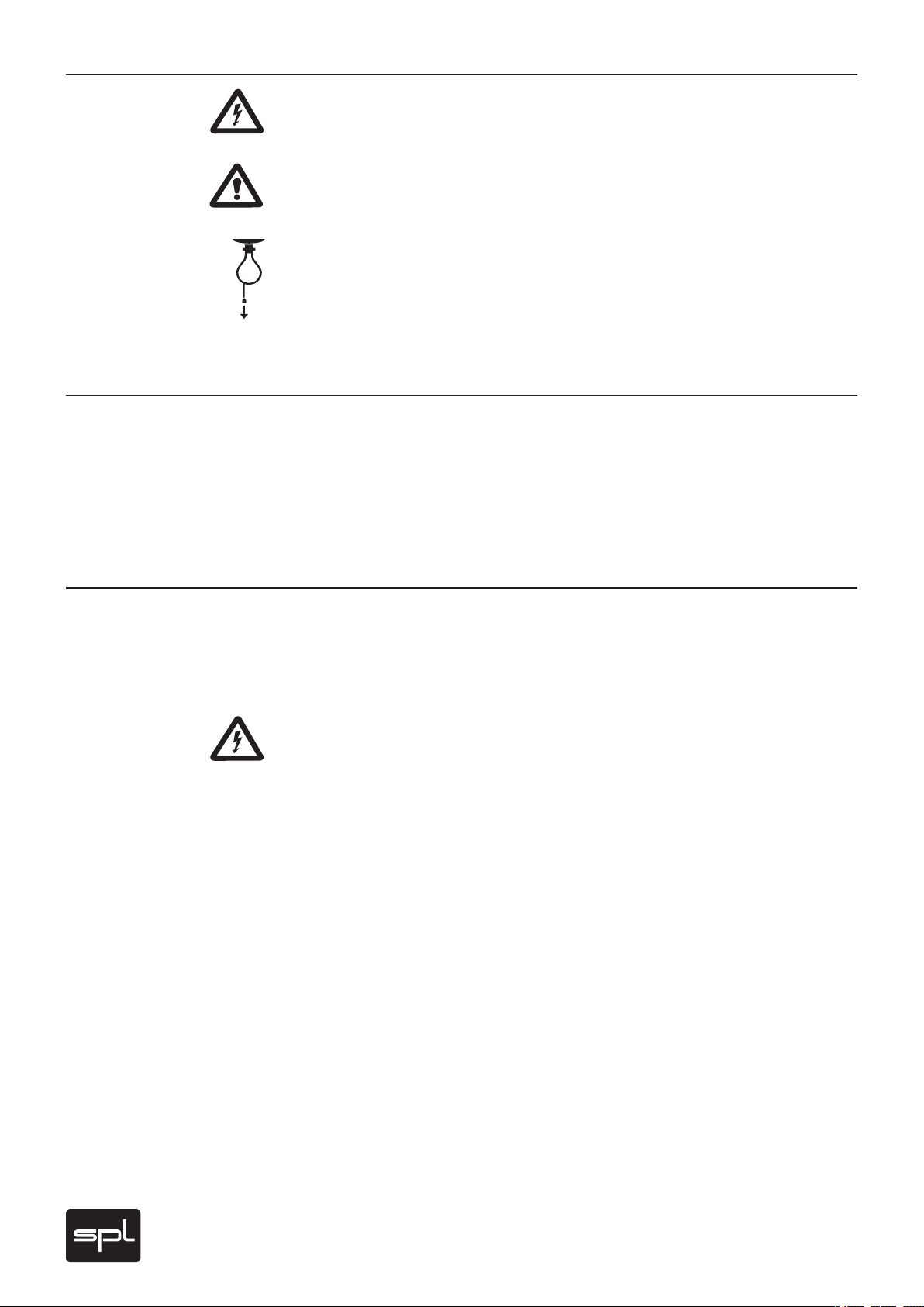
Live application: channel strip for vocals, one module used separately
Rear Panel
An example for a live setup: The compressor module is separated from the channel strip.
The vocal signal can be processed with all remaining modules, while the compressor is used
for processing bass. In the same way, each module can be taken out of the channel strip,
e. g. using the De-Esser separately while processing an acoustic guitar with the (remaining)
channel strip and so on. Detailed information on page 25.
Studio application: all inputs and outputs are routed to a patchbay
Our recommendation for studio wiring: all inputs and outputs are connected to a patchbay so
that each Frontliner module can be routed with maximum flexibility within a studio environment. Connections to a console or to DAW interfaces for example can always be configured
to meet the respective requirements. Aside from the switching options that the Frontliner
provides the sequence of modules can be determined in any way with the patchbay.
Page 10
10
Frontliner
Rear Panel
MIC IN
DISABLE
48V ON
FRONT
48V
ON
LINE IN
LINE IN
OUT
OUT
IN
IN
OUT
OUT
A D IN PU T 2
TO REDUCE RISK OF FIRE OR ELECTRIC SHOCK
DO NOT EXPOSE T HIS UNIT
TO RAIN OR MOIS TURE.
THIS EQUIPMENT MUST BE E ARTHED.
WARNING
AVIS: RISQUE DE CHOC ÉLEC TRIQUE - NE PAS OUVRIR
RISK OF ELECTRIC SHO CK
DO NOT OPEN
CAUTION
DISCRETE T UBE PREAMPLIFI ER
CONNECTOR WI RING
D IS CR E TE TU BE PR E AM P LI F IE R
DE-ESSER
D E- E S SE R
IN
IN
OUT
OUT
COMPRESSOR / L IM.
CO M PR E SS O R / L IM .
IN
IN
OUT
OUT
EQUALIZER / TUB E SAT.
EQ U AL I ZE R / T UB E S AT .
OUT 2
OUT 2
OUT 1
OUT 1
MAIN OUTPUT S
M A IN OU T P U TS
S P L CO N VE R TE R S L OT – OP T IO N AL
SPL CONVER TER SLOT – OPTI ONAL
CONVERTER SER IAL #
SoundPerformanceLab.com
MADE IN GERMAN Y
FRONTLINER SERI AL # OPTIONS
P OW E R
XLR WIRING: PIN 1 = GN D / PIN 2 = HOT (+) / PIN 3 = COLD (–)
TRS WIRING: TI P = LEFT / RING = RIGHT / SLEEVE = G ND
AD INPUT 2
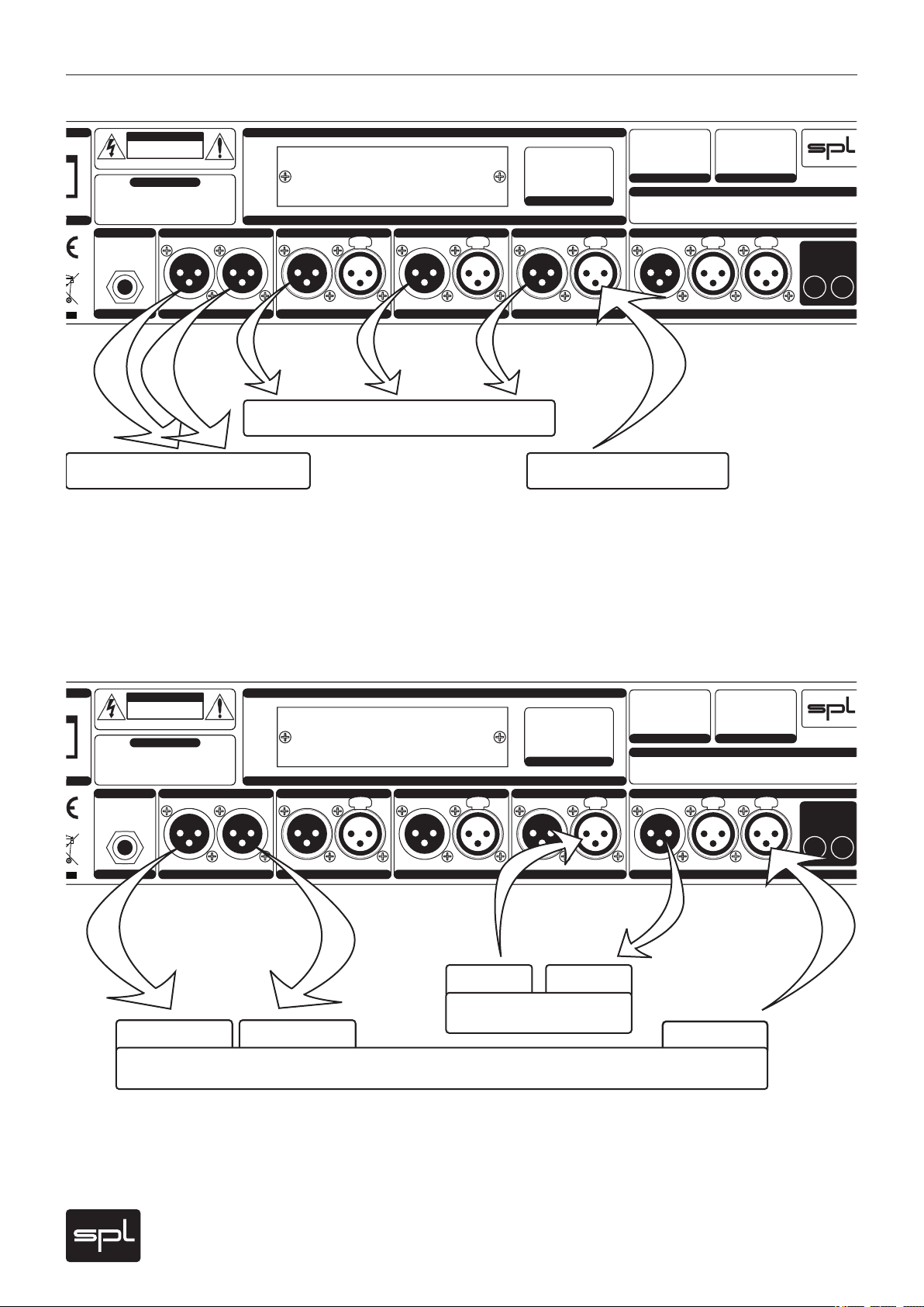
Signal input (line)
Option: use single outputs
2: Monitoring, 1: Recording
MIC IN
DISABLE
48V ON
FRONT
48V
ON
LINE IN
LINE IN
OUT
OUT
IN
IN
OUT
OUT
A D IN PU T 2
TO REDUCE RISK OF FIRE OR ELECTRIC SHOCK
DO NOT EXPOSE T HIS UNIT
TO RAIN OR MOIS TURE.
THIS EQUIPMENT MUST BE E ARTHED.
WARNING
AVIS: RISQUE DE CHOC ÉLEC TRIQUE - NE PAS OUVRIR
RISK OF ELECTRIC SHO CK
DO NOT OPEN
CAUTION
DISCRETE T UBE PREAMPLIFI ER
CONNECTOR WI RING
D IS CR E TE TU BE PR E AM P LI F IE R
DE-ESSER
D E- E S SE R
IN
IN
OUT
OUT
COMPRESSOR / L IM.
CO M PR E SS O R / L IM .
IN
IN
OUT
OUT
EQUALIZER / TUB E SAT.
EQ U AL I ZE R / T UB E S AT .
OUT 2
OUT 2
OUT 1
OUT 1
MAIN OUTPUT S
M A IN OU T P U TS
S P L CO N VE R TE R S L OT – OP T IO N AL
SPL CONVER TER SLOT – OPTI ONAL
CONVERTER SER IAL #
SoundPerformanceLab.com
MADE IN GERMAN Y
FRONTLINER SERI AL # OPTIONS
P OW E R
XLR WIRING: PIN 1 = GN D / PIN 2 = HOT (+) / PIN 3 = COLD (–)
TRS WIRING: TI P = LEFT / RING = RIGHT / SLEEVE = G ND
AD INPUT 2
2: Monitor 1: DAW
Microphone
SendReturn
Channel strip
External processor
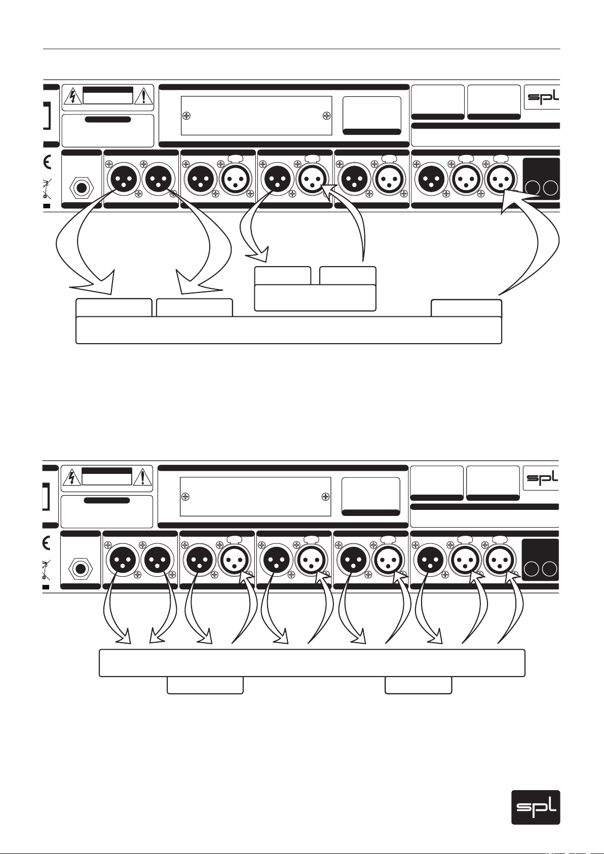
Wiring examples: group of modules, inserts
Excluding a group of modules from the channel strip
This example shows the exclusion of de-esser, compressor and EQ/tube saturation as a
group. The input signal is connected to the input of the first module. If all three processors are
excluded as a group, the output signal of the group is present at the MAIN OUTPUTS. If a dual
processor group is excluded, the output of the last module is always the group output. In the
example above the preamplifier can be used separately via its own I/Os. Further information
on page 25.
Determining inserts for external processors
You can determine inserts between every processing module. In the example above, an insert
is determined between preamplifier and de-esser. The insert is routed via preamplifier output
and de-esser input as send and return. Refer to page 26 for further information.
Page 11
11
Frontliner
Connections
Input
Output
balanced
unbalanced
balanced
unbalanced
1=GND
2=hot (+)
3=cold (-)
1
2
3
1
2
3
1
2
3
1
2
3
Signal connection
Switch off the unit before you begin the process of making the rst or any subsequent connections. Neglecting this can damage either or both your ears and your equipment.
1/4" TRS socket
The TRS socket AD INPUT 2 supports both balanced (1/4" TRS/stereo jack connector) and
unbalanced connections (1/4" TS/mono jack connector). Refer to page 13 for further information on that input.
XLR sockets
All XLR sockets are balanced inputs or outputs. Input sockets are always female for plugging
in male connectors, output sockets are always male for female connectors. All in all a comprehensible principle.
Balanced connections
It is impossible to exclude all interferences when a single audio signal is transmitted. Shielding
is effective against electric, but not against electromagnetic inuences. Motors, transformers,
and alternating current can always induce interferences. But even if the transmission would
succeed, differences in ground potentials between driver and receiver would produce disturbances.
Rear Panel
In balanced connections a reference signal with reversed polarity is transmitted additionally
to the audio signal through a second wire. The ground signal is routed separately through
a third wire. Input and output stages are drivers and receivers, and the receiving stage can
suppress interferences by subtracting the difference between audio and reference signal.
Unbalanced connections
Unbalanced connections from and to RCA or 1/4" TS sockets can be made without adaptors to
the balanced XLR sockets. The correct wiring is important. The diagram shows the pin conguration of the XLR sockets and how to correctly connect them for unbalanced connections:
Connections to RCA sockets are always unbalanced, a wiring to jack connectors can be both
balanced (1/4" TRS/stereo jack) or unbalanced (1/4" TS/mono jack). We recommend to use
individually congured cables from XLR to RCA or jack sockets instead of adaptors. You can
get cables in any needed conguration from audio dealers. With the diagram above, the dealer
can ensure to provide the appropriate cable for your application.
Page 12

12
Frontliner
Sockets
Rear Panel
Separate inputs and outputs
Each Frontliner module is equipped with its own input and output stage. An obvious purpose
is to route the signal from any output, e. g. right after the preamp to store the pure recording
signal. Further applications such as using single or grouped modules separately or inserting
external processors are depicted on pages 9 and 10. Inserts can be determined before each
processing module input.
Preampli er: MIC IN
You can connect any kind of microphone to the MIC IN socket (dynamic, condenser, tube and
ribbon microphones). 48 volts phantom power, which is required for some microphones, can
be activated with the 48V switches on the front or rear panel. Please read the important notes
in chapter “48V” on page 15. The microphone input can also be equipped with an optional
transformer (refer to page 27, “Information on I/O transformers”).
Preampli er: LINE IN
Use the balanced LINE IN socket for high-level signals with impedances lower than 1 kOhm,
e. g. D/A converters, synthesizers or samplers. We recommend connection to a patchbay for
easier access.
The maximum input level of the LINE IN is +22 dBu.
High impedance sources (above 1 kOhm), such as e-guitars and basses, acoustic guitars with
pick ups and so on, must be connected to the instrument input (see pages 16 and 17).
IM PO RTANT: The line input is deactivated if the instrument input is in use.
Preampli er: OUT
The electronically balanced, analog preampli er output provides the preampli ed signal prior
to any processing. If you determine an insert between preampli er and de-esser, the preampli er output serves as insert send.
De-Esser: IN and OUT
The analog de-esser input and output sockets are electronically balanced.
Normally the de-esser input signal is the internal preampli er signal. If you are using the
de-esser module separately as single module, you connect the source and receiving units to
the de-esser inputs and outputs. If you are using the de-esser module as part of a group of
modules, you connect the source and receiving units to the group inputs and outputs. If you
determine an insert between preampli er and de-esser, the de-esser input serves as insert
return.
MIC IN
DISABLE
48V ON
FRONT
48V
ON
LINE IN
LINE IN
OUT
OUT
IN
IN
OUT
OUT
230V ~50Hz
Fuse : 3 15mA slow
115V ~60Hz
Fuse : 630mA slow
A D I N P U T 2
TO RE DUCE RI SK O F FI RE O R E LEC TRIC SHO CK
DO NO T EX POS E T HIS UNIT
TO RA IN O R M OIS TURE .
THIS E QUIP MENT MUS T B E E ART HED.
WARNING
M A I N S I N P U T
MAINS INPUT
AVIS: RISQUE DE CHOC ÉLECTRIQUE - NE PAS OUVRIR
RISK OF ELECT RIC SHOC K
DO NOT OPEN
CAUTION
DISCRETE TUBE PREAMPLIFIER
CONNECTOR WIRING
D I S C R E T E T U B E P R E A M P L I F I E R
DE-ESSER
DE - E S S E R
IN
IN
OUT
OUT
COMPRESSOR / LIM.
C O M P R E S S O R / L I M .
IN
IN
OUT
OUT
EQUALIZER / TUBE SAT.
E Q U A L I Z E R / T U B E S A T .
OUT 2
OUT 2
OUT 1
OUT 1
MAIN OUTPUTS
M A I N O U T P U T S
S P L C O N V E R T E R S L O T – O P T I O N A L
SPL CONVERTER SLOT – OPTIONAL
CONVE RTER SERI AL #
SoundPerformanceLab.com
MADE IN GERMANY
FRONT LINER SER IAL # OP T I O N S
GND LIFT
GND LIFT
GND
G N D L I F T
POWER
P O W E R
V O L T A G E | F U S E
VOLTAGE | FUSE
XLR WIRING: PIN 1 = GND / PIN 2 = HOT (+) / PIN 3 = COLD (–)
TRS WIRING: TIP = LEFT / RING = RIGHT / SLEEVE = GND
AD INPUT 2
0
MIC INLINE IN
LINE IN
OUT
OUT
DISCRETE TUBE PREAMPLIFIER
D I SC R E T E T U B E P R E A M P L I FI E R
IN
IN
OUT
OUT
DE-ESSER
D E- E S S ER
Page 13

13
Frontliner
Sockets
IN
IN
OUT
OUT
COMPRESSOR / LIM.
C OM P R E S S O R / L I M .
IN
IN
OUT
OUT
EQUALIZER / TUBE SAT.
E Q UA L I Z E R / TU B E S AT .
OUT 2
OUT 2
OUT 1
OUT 1
MAIN OUTPUTS
M A I N O U T P U T S
A D IN P U T 2
AD INPUT 2
M A I NS I N P U T
MAINS INPUT
Compressor: IN and OUT
The analog compressor input and output sockets are electronically balanced.
Normally the compressor input signal is the internal de-esser signal (or the EQ signal if EQ
PRE COMP. is activated). If you are using the compressor module separately as single module,
you connect the source and receiving units to the compressor inputs and outputs. If you are
using the compres sor module separ ately as part of a mo dule group, yo u connec t the source and
receiving units to the group inputs and outputs. If you determine an insert between de-esser
and compressor, the de-esser output is the insert send and the compressor input is the insert
return.
Equalizer: IN and OUT
The analog equalizer/tube saturation input and output sockets are electronically balanced.
Normally the EQ input signal is the internal compressor signal (or the de-esser signal if EQ
PRE COMP. is activated). If you are using the equalizer module separately as single module, you
connect the source and receiving units to the equalizer inputs and outputs. If you are using the
equalizer module separately as part of a module group, you connect the source and receiving
units to the group inputs and outputs. If you determine an insert between compressor and
equalizer, the compressor output is the insert send and the equalizer input is the insert return.
Rear Panel
MAIN OUTPUTS: OUT 1 and OUT 2
The output signal of the channel strip is supplied by the electronically balanced, analog
outputs OUT 1 and OUT 2. The splitted outputs allow to feed recording and monitoring devices
simultaneously, or, in a live application, monitoring and P. A. paths. Each output is driven by its
own stage to exclude mutual inuences. OUT 1 can optionally be equipped with a transformer
(refer to page 27, “Information on I/O transformers”).
If you have excluded all three processing modules from the channel strip as a group, the
group’s output signal is supplied by the MAIN OUTPUTS. In this case, the preamplier output
signal is only present at the preamp’s output. In all other cases the nal output signal of the
channel strip is always present at the MAIN OUTPUTS.
AD Input 2
The Frontliner is a mono channel strip, but the optional A/D converter card 2376 is a dualchannel device. Therefore a second (external) signal can be converted with the converter
card, if it is connected to the AD INPUT 2. If no signal is connected to the A/D INPUT 2, the
output signal of the Frontliner is routed to both converter channels. The maximum input level
for the converter is +12dBu (=0 dBFS).
Power connection and fuses
Connect the power cord to the rear MAINS INPUT socket. Transformer, power cord and case
connection conform to VDE, UL and CSA requirements.
The Frontliner’s power supply houses two fuses, one for the neutral wire and one for the phase
conductor. The fuses are accessible from outside and placed right behind the ap below the
socket.
Fuse ratings are 315 mA slow blow (
230
volts) or 630 m A slow blow (
115
volts).
Page 14

14
Frontliner
Voltage Selector
The rear panel VOLTAGE SELECTOR sets the local line voltage (115 V position: 110-120
volts/6o Hz, 230 V position: 220-240 volts/50 Hz). The diagram shows the correct switch position for 230 V power supply.
BEFORE you connect electrical power make sure that the VOLTAGE SELECTOR
setting re ects the correct local power line voltage!
Power switch
The rear panel POWER switch activates the unit, con rmed by the illuminated VU meter.
Switch on the unit only after you have checked the correct setting of the rear
VOLTAGE SELECTOR and 48V phantom power supply front and rear switches.
When you activate the Frontliner, the unit commences the warm-up mode to heat
the tubes. The warm-up cycle takes between 45 seconds (if the unit was active shortly before)
and approximately one minute at cold start. During warm-up the MUTE switch ashes. The
MAIN OUTPUTS and the output to the optional converter card are muted, all EXTERNAL INPUTS
keys are deactivated. The MUTE switch stops ashing when warm-up is nished. The MUTE
switch does not illuminate if it was not depressed before. It illuminates permanently after
war m-up when it was activated before.
Phantom power supply/rear panel switches
48 Volt phantom power is only needed for microphones requiring external current
(generally condenser microphones). Other microphones can be damaged if they
are used with activated phantom power, which may damage the Frontliner, too.
Please read the notes on using phantom power and how to activate it under “48 V” on page
15 and “Activating Phantom Power” on page 16.
Since phantom power is critical to operational safety, the Frontliner offers additional switches
on the rear panel to exclude accidental use of the 48 V switch on the front.
If both rear panel switches are not engaged, you can activate and deactivate phantom power
with the 48 V switch on the front.
The switch to the right labelled 48 V ON activates phantom power independently from the
front panel switch setting – now phantom power can no longer be switched off with the front
panel switch.
The left rear panel switch labelled DISABLE 48 V ON FRONT deactivates the 48 V switch on the
front, now phantom power can no longer be activated accidentally with the front panel switch.
The 48 V switch on the front is always illuminated if phantom power is active.
GND Lift
The rear panel GND LIFT switch eliminates hum by separating the internal ground from the
unit’s housing ground. Hum can, for example, result when this unit’s housing has a common
ground connection with other devices that might have a different ground potential. The switch
is usually deactivated to retain the shielding of the housing.
Switches
Rear Panel
POWER
P O WE R
0
230V ~50Hz
Fuse : 315 mA slow
115V ~60Hz
Fuse : 630mA slow
V OL T AG E | F U S E
VOLTAGE | FUSE
GND LIFT
GND LIFT
GND
G N D L I F T
DISABLE
48V ON
FRONT
48V
ON
Page 15

15
Frontliner
Preamplier
7
5
3
1
0
3
5
30
50
70
100
VU
5
3
1
VU
20
10
0
%
M
I
C
G
A
I
N
S
-
R
E
D
U
C
T
I
O
N
I
N
S
T
R
U
M
E
N
T
S
-
D
E
T
E
C
T
A
D
-
O
V
L
1
3
1
4
1
5
1
6
1
8
2
0
2
2
2
4
2
6
2
8
3
0
3
3
3
6
3
9
4
2
4
5
5
2
6
1
6
8
I
N
S
T
R
.
G
A
I
N
L
I
N
E
G
A
I
N
R
A
T
I
O
A
T
T
A
C
K
L
M
F
M
H
F
L
M
F
–
/
+
M
H
F
–
/
+
A
I
R
B
A
N
D
T
U
B
E
S
A
T
U
R
A
T
I
O
N
INSTR.
LINE IN
TUBE
+15dB
ON ON
MUTE
EQ PRE
CO MP .
EQ/TU BECOM P.
EXTERNAL INPUT S
DE-ES.
AUTO
48 V PAD
Recording Channel
Ø
M
A
K
E
-
U
P
R
E
L
E
A
S
E
O
U
T
P
U
T
Sound Performan ce Lab Made in Germany
ON
0
-
1
-
2
-
3
-
4
-
6
-
9
-
1
1
-
1
2
2
1
1
6
1
1
6
0
-
5
-
9
-
1
6
-
2
2
-
3
0
-
3
8
-
4
6
-
5
4
-
5
8
1
.
2
1
.
4
1
.
7
2
.
0
2
.
3
2
.
7
3
.
0
3
.
6
5
.
0
1
6
∞
0
1
0
2
0
3
0
4
0
5
0
6
0
7
0
8
0
9
0
1
0
0
-
2
0
-
1
3
-
7
.
5
-
4
.
5
-
2
0
1
.
5
3
4
5
5
.
5
0
.
1
0
.
2
0
.
4
1
.
0
2
.
5
7
.
0
1
6
4
0
1
3
0
5
3
0
1
0
0
0
0
.
0
3
0
.
0
5
0
.
0
9
0
.
1
5
0
.
2
5
0
.
4
0
.
6
5
1
.
0
1
.
3
1
.
8
2
.
0
0
0
.
5
1
2
3
4
5
6
7
8
9
1
0
1
2
1
4
1
6
1
9
2
0
-
1
2
-
1
0
-
5
-
2
.
5
0
2
.
5
5
7
.
5
1
0
1
2
-
1
2
-
1
0
-
5
-
2
.
5
0
2
.
5
5
7
.
5
1
0
1
2
-
1
0
-
8
-
6
-
4
-
2
0
2
4
6
8
1
0
6
8
0
8
2
0
1
k
0
1
k
5
2
k
7
3
k
4
4
k
5
6
k
5
1
0
k
1
3
k
1
5
k
3
0
4
0
5
0
8
0
1
2
5
1
6
0
2
0
0
3
0
0
5
0
0
6
4
0
7
0
0
Model 2800
GRVU VU PPM 0 dB -10 dB
T
H
R
E
S
H
O
L
D
Frontliner
6
8
1
1
1
4
1
7
1
9
2
1
2
3
2
5
2
6
2
7
2
9
3
2
3
5
3
7
3
9
4
1
4
2
4
3
-
2
0
-
1
8
-
1
2
-
9
0
3
9
1
0
dB 1: x dB dB
dB dBHz
Hz %
ms s
dB dB
dB
48 V PADØ
M
I
C
G
A
I
N
1
3
1
4
1
5
1
6
1
8
2
0
2
2
2
4
2
6
2
8
3
0
3
3
3
6
3
9
4
2
4
5
5
2
6
1
6
8
dB
MIC GAIN
The MIC GAIN control determines the level of preamplication. The preamplication values
cover a range from +13 dB up to + 68 dB. If an optional microphone input transformer is tted
the scaled values are to be increased by ca. +14 dB (depends upon microphone. Further information on page 27, “Information on I/O transformers”). The potentiometer is a RK 27 from
ALPS, a high-grade model with antilogarithmic characteristic and an especially high resolution between 20 dB and 40 dB to allow for sensitive control within this most important range.
MIC GAIN adjustments
Amplifying a mic signal to line level should principally be done solely with the MIC GAIN
control. Deactivate all processing modules in the rst place. The OUTPUT level control is used
to adjust the proper drive level for subsequent equipment, so initially it should be set to 0 dB
(12 o’clock position). The 0 dB/-10 dB switch should be set to 0dB as well to see the overall
output level (also see “0 dB/-10 dB” on page 23).
Control Elements
Now turn up the MIC GAIN control until the VU shows maximum values between 0 dB and
+3 dB. There is still enough headroom to prevent clipping at varying input levels. Note that
the VU meter shows average levels instead of peak levels (which can be up to 10 dB higher). If
necessary, switch the VU to PPM mode to see peak levels (see “VU/PPM switch” on page 23).
In recording high-level signals such as snare and kick, etc. it may be necessary to engage the
PAD switch (see “PAD” on page 16). You can drive the MIC GAIN harder if you know that unexpected input level changes are unlikely to occur. Choose the -10dB setting with the 0 dB/-10 dB
switch to extend the VU meter range accordingly.
48 V
The 48 V switch activates phantom power for condenser microphones with built-in ampliers.
Phantom power should only be activated when using microphones that require it.
VERY IMPORTANT: All microphones with balanced, ground-free outputs, can be used with
the phantom power activated. Please be sure to deactivate phantom power with all other
microphones. Unbalanced microphones may only be used with phantom power deactivated.
Since phantom power is critical to operational safety, the Frontliner offers additional switches
on the rear panel to exclude accidental use of the 48 V switch on the front. The function of
these rear panel switches is described on the previous page.
Activating phantom power
PLEASE ALWAYS FOLLOW THESE INSTRUCTIONS TO ACTIVATE AND DEACTIVATE PHANTOM
POWER (ALSO WHEN CHANGING MICROPHONES). THE FRONTLINER’S INPUT STAGE CAN BE
DAMAGED IF YOU IGNORE THESE PROCEDURES!
1. Connect the microphone to the Frontliner.
2. Now activate phantom power to use the microphone.
3. When nished, rst deactivate phantom power.
4. Wait at least one minute after deactivation of phantom power before disconnecting the
microphone! This ensures residual current will be discharged.
Page 16

16
Frontliner
Control Elements
48 V PADØ
48 V PADØ
48 V PADØ
I
N
S
T
R
U
M
E
N
T
Preamplier
Phase reverse
The phase reverse function reverses the polarity of the microphone signal, inverting the
phase (by 180°) to correct phase-inverted signals caused by multiple signal sources. A voiceover artist, for example, hears himself during recording through the headphones and simultaneously through the bones in his head. Phase inversion will cause an unnatural sound, and
even minimal variations in distance to the microphone will cause drastic variations in the
sound. Phase inversion is also commonly encountered when using multiple microphones on
a single sound source. We recommend checking for correct polarity before each recording.
Phase reverse can be applied to the preamplier microphone and line inputs.
High-pass filter
This switch activates the high-pass lter, which operates from 85 Hz downwards with 6 dB/
octave (often also called a “rumble lter“). The lter prevents the amplication of unwanted
low-frequencies. Compared to 12 dB/octave lters, the 6 dB lter works relatively moderate,
but very musical.
The high-pass filter can be applied to all three preamplier inputs (microphone, line, and
instrument).
PAD
The PAD switch attenuates the microphone input by 20dB. High-level input signals can be
attenuated in order to prevent over-driving the preamplier. The Frontliner has a minimum
pre-amplication of +13 dB. But with signals from drums or brass this may already be too
much. Engaging PAD attenuates the minimum pre-amplication (MIC GAIN control fully
counter clockwise) to -7 dB, thus providing a useful gain control range for loud input signals.
INSTRUMENT input
The INSTRUMENT input jack is placed on the front for easy access. It should be used to connect
instruments like e-bass and guitars, acoustic guitars with pick-ups, etc. The Instrument input
features a 1 MOhm (one mega Ohm) input impedance. Line signals with lower impedances,
such as from D/A converters, samplers, synths, etc. should be connected to the rear LINE IN
socket.
IMPORTANT: As long as an instrument is plugged into front INSTRUMENT input, the rear
panel LINE IN input is deactivated.
Page 17

17
Frontliner
Preamplier
INSTR.
LINE IN
TUBE
+15 dB
I
N
S
T
R
.
G
A
I
N
L
I
N
E
G
A
I
N
6
8
1
1
1
4
1
7
1
9
2
1
2
3
2
5
2
6
2
7
2
9
3
2
3
5
3
7
3
9
4
1
4
2
4
3
-
2
0
-
1
8
-
1
2
-
9
0
3
9
1
0
dB
INSTR.
LINE IN
TUBE
+15 dB
LINE GAIN/INSTR. GAIN
This control determines the level of preamplication for signals connected either to the rear
LINE IN or to the INSTRUMENT input on the front. You activate the respective input with the
INSTR./LINE IN switch which is described below.
Gain range for line signals reaches from -20 dB to +10 dB. The attenuation allows to also
process very high levels.
Instrument signals can be amplied between +6 dB and +43 dB.
LINE GAIN and INSTR. GAIN adjustments
For optimal leveling of line or instrument signals, deactivate all processing modules and set the
OUTPUT level control to 0 dB (12 o’clock position). The VU meter’s 0 dB/-10 dB switch should be
set to 0dB to see the correct output level (also see “0 dB/-10 dB” on page 23).
Now turn up the LINE GAIN/INSTR. GAIN control until the VU shows maximum values between
0 dB and +3 dB. There is still enough headroom to prevent clipping at varying input levels.
Note that the VU meter shows average levels instead of peak levels (which can be up to 10 dB
higher). If necessary, switch the VU to PPM mode to see peak levels (see “VU/PPM switch” on
page 23).
Levels between 0 and +3 dB usually are safe. Attenuate very high input levels with the LINE GAIN
control. Switch the VU meter to -10 dB display mode to extend the metering range accordingly.
Control Elements
INSTR./LINE IN
With this switch you select between the microphone (off ) and line or instrument inputs (on).
The rear mic and line inputs can remain connected, regardless of which input is selected. You
can choose the line input as source as long as the instrument input is not being used.
TUBE + 15 dB
The TUBE +15 dB switch increases the degree of tube preamplication. The switch changes
from standard tube preamplication (+6 dB) to +15 dB. In each setting the total output
level of the preamp is automatically accommodated so that output levels do not have to be
re-calibrated when the tube is driven hotter – therefore MIC GAIN settings do not have to be
changed.
Engaging the TUBE +15 dB switch has an impact on the overall sound, as it directly changes
the sonic character of the tube. The higher the input level, the more you will notice the effects
of the tube’s typical even harmonic distortion.
Driving the tube with +15 dB creates subtle to modest presence effects which can put the
signal up front in a mix. For decent effects you should not apply too high MIC GAIN values with
the TUBE +15 dB switch engaged.
Page 18

18
Frontliner
Control Elements
ON
S
-
R
E
D
U
C
T
I
O
N
0
-
1
-
2
-
3
-
4
-
6
-
9
-
1
1
-
1
2
dB
S
-
D
E
T
E
C
T
7
5
3
1
0
3
5
30
50
70
100
VU
5
3
1
VU
20
10
0
%
M
I
C
G
A
I
N
S
-
R
E
D
U
C
T
I
O
N
I
N
S
T
R
U
M
E
N
T
S
-
D
E
T
E
C
T
A
D
-
O
V
L
1
3
1
4
1
5
1
6
1
8
2
0
2
2
2
4
2
6
2
8
3
0
3
3
3
6
3
9
4
2
4
5
5
2
6
1
6
8
I
N
S
T
R
.
G
A
I
N
L
I
N
E
G
A
I
N
R
A
T
I
O
A
T
T
A
C
K
L
M
F
M
H
F
L
M
F
–
/
+
M
H
F
–
/
+
A
I
R
B
A
N
D
T
U
B
E
S
A
T
U
R
A
T
I
O
N
INSTR.
LINE IN
TUBE
+15dB
ON ON
MUTE
EQ PRE
CO MP .
EQ/TU BECOM P.
EXTERNAL INPUT S
DE-ES.
AUTO
48 V PAD
Recording Channel
Ø
M
A
K
E
-
U
P
R
E
L
E
A
S
E
O
U
T
P
U
T
Sound Performan ce Lab Made in Germany
ON
0
-
1
-
2
-
3
-
4
-
6
-
9
-
1
1
-
1
2
2
1
1
6
1
1
6
0
-
5
-
9
-
1
6
-
2
2
-
3
0
-
3
8
-
4
6
-
5
4
-
5
8
1
.
2
1
.
4
1
.
7
2
.
0
2
.
3
2
.
7
3
.
0
3
.
6
5
.
0
1
6
∞
0
1
0
2
0
3
0
4
0
5
0
6
0
7
0
8
0
9
0
1
0
0
-
2
0
-
1
3
-
7
.
5
-
4
.
5
-
2
0
1
.
5
3
4
5
5
.
5
0
.
1
0
.
2
0
.
4
1
.
0
2
.
5
7
.
0
1
6
4
0
1
3
0
5
3
0
1
0
0
0
0
.
0
3
0
.
0
5
0
.
0
9
0
.
1
5
0
.
2
5
0
.
4
0
.
6
5
1
.
0
1
.
3
1
.
8
2
.
0
0
0
.
5
1
2
3
4
5
6
7
8
9
1
0
1
2
1
4
1
6
1
9
2
0
-
1
2
-
1
0
-
5
-
2
.
5
0
2
.
5
5
7
.
5
1
0
1
2
-
1
2
-
1
0
-
5
-
2
.
5
0
2
.
5
5
7
.
5
1
0
1
2
-
1
0
-
8
-
6
-
4
-
2
0
2
4
6
8
1
0
6
8
0
8
2
0
1
k
0
1
k
5
2
k
7
3
k
4
4
k
5
6
k
5
1
0
k
1
3
k
1
5
k
3
0
4
0
5
0
8
0
1
2
5
1
6
0
2
0
0
3
0
0
5
0
0
6
4
0
7
0
0
Model 2800
GRVU VU PPM 0 dB -10 dB
T
H
R
E
S
H
O
L
D
Frontliner
6
8
1
1
1
4
1
7
1
9
2
1
2
3
2
5
2
6
2
7
2
9
3
2
3
5
3
7
3
9
4
1
4
2
4
3
-
2
0
-
1
8
-
1
2
-
9
0
3
9
1
0
dB 1: x dB dB
dB dBHz
Hz %
ms s
dB dB
dB
De-Esser
ON
The first processing module is the de-esser, which removes disturbing sibilants when
required. The de-esser module is activated with the ON button. The S-DETECT LED above the
ON switch shows that S-sounds are being detected.
S-REDUCTION
With the S-REDUCTION control you determine the intensity of S-sound reduction. The
processing is related to the levels of the entire frequency spectrum (see next section), therefore it is more intensive with extreme S-sound levels than with those of lower levels. This
equalizes levels of sibilants in the output signal.
SPL De-Esser technology
In contrast to common de-essers based upon compressor techniques the SPL De-Esser makes
use of the phase cancellation principle. It employs filters that process only the reducible
”S-frequencies” but do not interfere with the remainder of the spectrum. The S-frequencies
are detected automatically, the phase is inverted and mixed with the original signal. This
method of operation has distinct advantages because it is unobtrusive and helps retain the
original tonal quality. Compressor-typical side effects such as lisping or nasal tones do not
occur. Finally its operation is as simple as pulling on the hand brake.
The reduction is accomplished by comparing the average level with the individual S-sounds:
the de-esser functions only when the S-noise level exceeds the average level of the entire
frequency spectrum. This means for example that original S-sounds with a certain S-portion
are not processed whereas those that are too loud, or do not effectively contribute to the
sound, are reduced – but the character of the voice remains unchanged.
A further specialty is the integrated Auto Threshold function which makes processing independent of the input level. Even when the speaker or singer does not maintain a constant distance
to the microphone, processing is retained at the pre-set S-reduction value. Conventional
systems are dependent on the input level and work more intensively as the distance to the
microphone is reduced. As a result, the SPL De-Esser does not need to be monitored and
re-adjusted permanently to keep processing constant – and it can always be applied before
the compressor, as changing its position would not be an advantage. That is why an accordant
switching function is not necessary.
Page 19

19
Frontliner
Compressor/Limiter
7
5
3
1
0
3
5
30
50
70
100
VU
5
3
1
VU
20
10
0
%
M
I
C
G
A
I
N
S
-
R
E
D
U
C
T
I
O
N
I
N
S
T
R
U
M
E
N
T
S
-
D
E
T
E
C
T
A
D
-
O
V
L
1
3
1
4
1
5
1
6
1
8
2
0
2
2
2
4
2
6
2
8
3
0
3
3
3
6
3
9
4
2
4
5
5
2
6
1
6
8
I
N
S
T
R
.
G
A
I
N
L
I
N
E
G
A
I
N
R
A
T
I
O
A
T
T
A
C
K
L
M
F
M
H
F
L
M
F
–
/
+
M
H
F
–
/
+
A
I
R
B
A
N
D
T
U
B
E
S
A
T
U
R
A
T
I
O
N
INSTR.
LINE IN
TUBE
+15dB
ON ON
MUTE
EQ PRE
CO MP .
EQ/TU BECOM P.
EXTERNAL INPUT S
DE-ES.
AUTO
48 V PAD
Recording Channel
Ø
M
A
K
E
-
U
P
R
E
L
E
A
S
E
O
U
T
P
U
T
Sound Performan ce Lab Made in Germany
ON
0
-
1
-
2
-
3
-
4
-
6
-
9
-
1
1
-
1
2
2
1
1
6
1
1
6
0
-
5
-
9
-
1
6
-
2
2
-
3
0
-
3
8
-
4
6
-
5
4
-
5
8
1
.
2
1
.
4
1
.
7
2
.
0
2
.
3
2
.
7
3
.
0
3
.
6
5
.
0
1
6
∞
0
1
0
2
0
3
0
4
0
5
0
6
0
7
0
8
0
9
0
1
0
0
-
2
0
-
1
3
-
7
.
5
-
4
.
5
-
2
0
1
.
5
3
4
5
5
.
5
0
.
1
0
.
2
0
.
4
1
.
0
2
.
5
7
.
0
1
6
4
0
1
3
0
5
3
0
1
0
0
0
0
.
0
3
0
.
0
5
0
.
0
9
0
.
1
5
0
.
2
5
0
.
4
0
.
6
5
1
.
0
1
.
3
1
.
8
2
.
0
0
0
.
5
1
2
3
4
5
6
7
8
9
1
0
1
2
1
4
1
6
1
9
2
0
-
1
2
-
1
0
-
5
-
2
.
5
0
2
.
5
5
7
.
5
1
0
1
2
-
1
2
-
1
0
-
5
-
2
.
5
0
2
.
5
5
7
.
5
1
0
1
2
-
1
0
-
8
-
6
-
4
-
2
0
2
4
6
8
1
0
6
8
0
8
2
0
1
k
0
1
k
5
2
k
7
3
k
4
4
k
5
6
k
5
1
0
k
1
3
k
1
5
k
3
0
4
0
5
0
8
0
1
2
5
1
6
0
2
0
0
3
0
0
5
0
0
6
4
0
7
0
0
Model 2800
GRVU VU PPM 0 dB -10 dB
T
H
R
E
S
H
O
L
D
Frontliner
6
8
1
1
1
4
1
7
1
9
2
1
2
3
2
5
2
6
2
7
2
9
3
2
3
5
3
7
3
9
4
1
4
2
4
3
-
2
0
-
1
8
-
1
2
-
9
0
3
9
1
0
dB 1: x dB dB
dB dBHz
Hz %
ms s
dB dB
dB
ON AUTO
A
T
T
A
C
K
0
.
1
0
.
2
0
.
4
1
.
0
2
.
5
7
.
0
1
6
4
0
1
3
0
5
3
0
1
0
0
0
ms
2
1
1
6
1
1
6
0
-
5
-
9
-
1
6
-
2
2
-
3
0
-
3
8
-
4
6
-
5
4
-
5
8
T
H
R
E
S
H
O
L
D
dB
R
A
T
I
O
1
.
2
1
.
4
1
.
7
2
.
0
2
.
3
2
.
7
3
.
0
3
.
6
5
.
0
1
6
∞
1:x
ON
The On button activates the compressor/limiter module. Set the VU/GR switch to GR (=gain
reduction) to see the processing intensity (for further information read ”MAKE UP” on page
20) .
Usually the signal ow follows the design of the Frontliner, so the input signal normally comes
from the de-esser. However, with the EQ PRE COMP. switch the compressor/limiter module can
be switched behind the equalizer. This allows the compressor to be used as a nal compressor
or limiter after the equalizer (see „EQ PRE COMP” on page 15).
THRESHOLD
Control Elements
The THRESHOLD control determines the compressor threshold value, thus from which level
the compressor starts working. The value scale for the THRESHOLD control indicates the level
in dBu and ranges from 21 dB (fully lef t) to -58 dB (fully right). Turning the control to the right
intensies processing: fully lef t provides no compression, and fully right provides compression starting at a level of approximately -58 dBu.
RATIO
The RATIO control is used to set the ratio between the original signal and the compressed
signal. A ratio of 1:5 (RATIO control set to 5.0) means that a level increase of 5 dB on the input
results in an output level change of 1 dB. The more the control is turned right, the more ‘dense’
the sound becomes. The compressor works as a limiter when RATIO is turned fully right to
innity.
ATTACK
The ATTACK control determines how fast the compressor reacts. When turned fully lef t this
time is 0.1 milliseconds, and turned fully right the time is approximately 1000 milliseconds
(one second). Sudden, fast and impulsive attacks are called transients, they are produced for
example by hitting a drum. We identify natural sounds by transients, so they are enormously
important for sound impressions.
With very short ATTACK times the compressor reacts to every level jump and all transients are
processed. With slower settings, transients become more and more audible – a drum kit for
example can achieve more presence in a mix and sound faster with such settings. The best
ATTACK settings are not always easy to nd, since you usually need to nd a compromise.
Very fast settings run the risk of producing audible distortions – especially in the case of low
frequencies, since the compressor now tries to catch each waveform rise. The corresponding
control signal assumes a “saw-tooth” form which distorts the audio signal. To suppress this
effect, you would have to again increase the attack time until distortion no longer occurs – but
without missing the aim of processing.
The Frontliner offers a switchable automation feature for the ATTACK and RELEASE parameters to achieve perfect results when you are not satised with x settings (see next page).
Page 20

20
Frontliner
Control Elements
R
E
L
E
A
S
E
0
.
0
3
0
.
0
5
0
.
0
9
0
.
1
5
0
.
2
5
0
.
4
0
.
6
5
1
.
0
1
.
3
1
.
8
2
.
0
s
ON AUTO
ON AUTO
M
A
K
E
-
U
P
0
0
.
5
1
2
3
4
5
6
7
8
9
1
0
1
2
1
4
1
6
1
9
2
0
dB
Compressor/Limiter
ATTACK with cruise control: AUTO mode
The disadvantage of a usual ATTACK control: the setting refers to one critical moment, but it is
not optimal in every moment. But when you switch to AUTO mode, the ATTACK settings interactively respond to the input signal curves. Moreover, the automation can still be inuenced
manually. With the ATTACK control you can determine the range in which the automation sets
it’s values. Much like a cruise control resumes up to the set speed, the AUTO mode does the
same for the (automated) ATTACK time settings. The more you turn ATTACK to the right, the
broader is the range for the automation to set time values – the ATTACK setting you have chosen
is the maximum ATTACK time the automation applies.
RELEASE
The RELEASE control determines the time the compressor needs to get back to the initial
value af ter a level reduction. Turned fully left this time is ca. 0.03 seconds, or ca. 2 seconds
for fully right.
Just like setting the ATTACK it can be difcult to nd perfect RELEASE settings – for the same
compromising reason. Fast transients need short RELEASE times, but processing each and
every dynamic change bears the danger to produce rough, distorted sounds. Longer RELEASE
times sound smoother, but now transients may slip through. Again the AUTO mode can help
to achieve better results.
RELEASE with cruise control: AUTO mode
The AUTO mode for RELEASE rst determines the average level of the signal. Then the automation refers to this level to achieve a balanced control characteristic: short and loud peaks
can be processed very fast, but especially with complex material (summed signals) not every
small peak near the average level is included into the processing.
The RELEASE automation can be inuenced manually, too: the shorter the RELEASE time
ist set, the smaller is the range in which the processing follows the signal. Thus, with short
RELEASE times the processing follows very precisely and nearly “sticks” to the signal curve.
Short RELEASE times are for example adequate for percussive signals. If you apply longer
RELEASE times, the range is getting broader. Medium to slow settings can be recommended
for summed signals.
The AUTO switch activates ATTACK and RELEASE automation simultaneously. It is always
very effective to gain maximum loudness with minimum consequences in a musical sense.
This applies to all kinds of signals, from percussive sounds to vocals and instruments, and
aside from single tracks especially also to the complex structures of summed signals ... not to
mention a kind of signal that’s as difcult as it is common, called “untrained voice”.
MAKE UP
With the MAKE UP control you can make up the output gain that’s lost through compression.
It changes the output level within a range of 0 dB to +20 dB. Setting is very easy when you
switch the VU/GR switch below the VU meter to “GR” (GR=gain reduction). If for example the
loudest peal causes a maximum reduction of -9 dB, you adjust the MAKE UP control to +9dB.
Switch the compressor out now to perceive the loudness gain.
Page 21

21
Frontliner
Equalizer/Tube Saturation
7
5
3
1
0
3
5
30
50
70
100
VU
5
3
1
VU
20
10
0
%
M
I
C
G
A
I
N
S
-
R
E
D
U
C
T
I
O
N
I
N
S
T
R
U
M
E
N
T
S
-
D
E
T
E
C
T
A
D
-
O
V
L
1
3
1
4
1
5
1
6
1
8
2
0
2
2
2
4
2
6
2
8
3
0
3
3
3
6
3
9
4
2
4
5
5
2
6
1
6
8
I
N
S
T
R
.
G
A
I
N
L
I
N
E
G
A
I
N
R
A
T
I
O
A
T
T
A
C
K
L
M
F
M
H
F
L
M
F
–
/
+
M
H
F
–
/
+
A
I
R
B
A
N
D
T
U
B
E
S
A
T
U
R
A
T
I
O
N
INSTR.
LINE IN
TUBE
+15dB
ON ON
MUTE
EQ PRE
COM P.
EQ/TU BECOM P.
EXTERNAL INPUT S
DE-ES.
AUTO
48 V PAD
Recording Channel
Ø
M
A
K
E
-
U
P
R
E
L
E
A
S
E
O
U
T
P
U
T
Sound Performan ce Lab Made in Germany
ON
0
-
1
-
2
-
3
-
4
-
6
-
9
-
1
1
-
1
2
2
1
1
6
1
1
6
0
-
5
-
9
-
1
6
-
2
2
-
3
0
-
3
8
-
4
6
-
5
4
-
5
8
1
.
2
1
.
4
1
.
7
2
.
0
2
.
3
2
.
7
3
.
0
3
.
6
5
.
0
1
6
∞
0
1
0
2
0
3
0
4
0
5
0
6
0
7
0
8
0
9
0
1
0
0
-
2
0
-
1
3
-
7
.
5
-
4
.
5
-
2
0
1
.
5
3
4
5
5
.
5
0
.
1
0
.
2
0
.
4
1
.
0
2
.
5
7
.
0
1
6
4
0
1
3
0
5
3
0
1
0
0
0
0
.
0
3
0
.
0
5
0
.
0
9
0
.
1
5
0
.
2
5
0
.
4
0
.
6
5
1
.
0
1
.
3
1
.
8
2
.
0
0
0
.
5
1
2
3
4
5
6
7
8
9
1
0
1
2
1
4
1
6
1
9
2
0
-
1
2
-
1
0
-
5
-
2
.
5
0
2
.
5
5
7
.
5
1
0
1
2
-
1
2
-
1
0
-
5
-
2
.
5
0
2
.
5
5
7
.
5
1
0
1
2
-
1
0
-
8
-
6
-
4
-
2
0
2
4
6
8
1
0
6
8
0
8
2
0
1
k
0
1
k
5
2
k
7
3
k
4
4
k
5
6
k
5
1
0
k
1
3
k
1
5
k
3
0
4
0
5
0
8
0
1
2
5
1
6
0
2
0
0
3
0
0
5
0
0
6
4
0
7
0
0
Model 2800
GRVU VU PPM 0 dB -10 dB
T
H
R
E
S
H
O
L
D
Frontliner
6
8
1
1
1
4
1
7
1
9
2
1
2
3
2
5
2
6
2
7
2
9
3
2
3
5
3
7
3
9
4
1
4
2
4
3
-
2
0
-
1
8
-
1
2
-
9
0
3
9
1
0
dB 1: x dB dB
dB dBHz
Hz %
ms s
dB dB
dB
ON
EQ PRE
CO M P.
M
H
F
6
8
0
8
2
0
1
k
0
1
k
5
2
k
7
3
k
4
4
k
5
6
k
5
1
0
k
1
3
k
1
5
k
Hz
M
H
F
–
/
+
-
1
2
-
1
0
-
5
-
2
.
5
0
2
.
5
5
7
.
5
1
0
1
2
dB
ON
The ON switch adds the Equalizer/Tube Saturation module to the signal path. Usually the
input signal comes from the compressor module. With the EQ PRE COMP. key you can switch
the EQ module in front of the compressor, so that the input signal for the EQ module comes
from the De-Esser module.
EQ PRE COMP.
The EQ PRE COMP. key reverses the sequence of Compressor/Limiter and Equalizer: When the
key is pressed the Equalizer operates in front of the Compressor/Limiter; when not pressed
the succession remains unchanged.
Application examples: use of the compressor module as a limiter to maintain a stable output
level. If the EQ was to be used again after limiting it could not be guaranteed that the output
level would not alter. Or reduce frequencies with the EQ to prevent too excessive reactions
within the compressor, respectively vice versa: emphasize frequencies to let the compressor
react more intensively.
Control Elements
The EQ PRE COMP. key only switches the equalizer module, but not the tube saturation stage.
This function can also be used if compressor and EQ are taken out of the channel strip unit as
a group. In this case the signal connected to the compressor inputs is directly routed to the
EQ inputs. The EQ PRE COMP. function can not be activated if the compressor or EQ module is
is excluded from the channel strip via EXTERNAL INPUTS and operated as a single module or
if an insert was determined via the compressor or EQ inputs. The EQ PRE COMP. key ashes, if
the function is not accessible for one of the mentioned reasons.
MHF (mid-/high lter)
The MHF control serves to set the center frequency of the semi-parametric mid/high lter. The
control range is between 680 Hz and 15 kHz, so the lter covers a broad range of 4.5 octaves
for processing of both mid and high frequencies.
MHF -/+ (cut/boost MHF)
The MHF -/+ control determines the boost, or cut of the mid/high lter; the maximum values
range up to +/- 12 dB. The lter utilizes the proportional-Q principle. In other words the bandwidth (=Q ) is dependent on the selected boost or cut. Higher boost or cut values narrow the
bandwidth; with lower boost or cut values the bandwidth broadens. This lter characteristic
permits a musically more sensible processing of the frequency spectrum than with constantQ lters: if a more thorough setting has been chosen this will lead to a precise denition of
the frequency range to be processed. This in turn minimizes inuences from adjacent ranges.
This lter construction permits the complete scope, from selective removal of accentuated
frequencies through to character giving accentuations, to be effectively and quickly covered.
Recommendation on frequency settings: To nd the frequency which is to be processed as
quickly and accurately as possible, rstly adjust the MHF -/+ control to the maximum position. Subsequently the relevant frequency should be sought. Because the lter at maximum
setting works with the smallest bandwidth, the frequencies can be heard most distinctly at
this setting, making them easier to locate. Finally the desired MHF +/- setting can be applied
after the frequency is determined with MHF.
LMF (low/mid lter)
Page 22

22
Frontliner
Control Elements
L
M
F
3
0
4
0
5
0
8
0
1
2
5
1
6
0
2
0
0
3
0
0
5
0
0
6
4
0
7
0
0
Hz
L
M
F
–
/
+
-
1
2
-
1
0
-
5
-
2
.
5
0
2
.
5
5
7
.
5
1
0
1
2
dB
A
I
R
B
A
N
D
-
1
0
-
8
-
6
-
4
-
2
0
2
4
6
8
1
0
dB
T
U
B
E
S
A
T
U
R
A
T
I
O
N
0
1
0
2
0
3
0
4
0
5
0
6
0
7
0
8
0
9
0
1
0
0
%
Equalizer/Tube Saturation
The center frequency of the half-parametric low/mid f ilter is set with the LMF control. The
adjustable frequency range lies between 30 and 700 Hz so that this filter covers a range of
about 4.5 octaves, allowing it to be used from the deepest bass to the lower mid range. This
together with the mid/high filter ensures that the entire frequency spectrum is covered.
LMF -/+ (cut/boost LMF)
The LMF-/+ control determines the cut or boost of the LMF filter; the maximum values are +/12 dB. The LMF filter also operates to the proportional-Q principle, in other words the bandwidth is dependent on the selected boost or cut. The LMF filter can be applied in many ways.
Examples are to accentuate the fundamental sound of a voice, to cut “boom frequencies” and
for placement of instruments such as bass guitar, bass drums or synthesizers, both during
recording or subsequently when mixing.
Recommendation on frequency settings: To nd the frequency which is to be processed as
quickly and accurately as possible, rstly adjust the LMF -/+ control to the maximum position. Subsequently the relevant frequency should be sought. Because the lter at maximum
setting works with the smallest bandwidth, the frequencies can be heard most distinctly at
this setting, making them easier to locate. Finally the desired LMF +/- setting can be applied
after the frequency is determined with LMF.
AIR BAND
The high frequency filter in the equalizer module is described as the AIR BAND. A coil/capacitor filter with so called bell characteristics and a center frequency of 17.5 kHz comes into
operation here. At this frequency the maximum possible accentuation is +10 dB, the maximum
possible damping is -10 dB. The soft and natural tonal characteristic of the coil-capacitor filter
lends itself extremely well to provide clarity and, well ... air to vocals in the upper frequency
range, thereby improving their presence. On the other hand harsh sounds can be lent a more
pleasant sound characteristic through damping.
TUBE SATURATION
With this control you determine the amount of tube saturation. The output level is accommodated automatically, in extreme settings the level increases by only 6 dB. Therefore you can
easily dial in decent to expressive harmonic distortions with the TUBE SATURATION control by
turning just one knob.
Saturation effects are generated through the tube being pushed to and beyond its normal
operating limits. In contrast to semiconductors, a tube thus pushed to such levels does not
clip from a certain level, approaching more gradually its level limits and thereby producing
its typical tonal result, which in audio signal processing can have such of ten protable aural
effects —on one hand (and depending on the amount applied), from subtle to extensive
harmonic distortion and on the other hand, a compaction of the sonic event, that is, a limiting
effect that exhibits a pleasant, rounded or soft sound. Acoustically and also in its range of
applications this can be compared very well with tape saturation effects.
Page 23

23
Frontliner
VU-Meter
0 dB -10 dB
GRVU
VU PPM
7
5
3
1
0
3
5
30
50
70
100
VU
5
3
1
VU
20
10
0
%
M
I
C
G
A
I
N
S
-
R
E
D
U
C
T
I
O
N
I
N
S
T
R
U
M
E
N
T
S
-
D
E
T
E
C
T
A
D
-
O
V
L
1
3
1
4
1
5
1
6
1
8
2
0
2
2
2
4
2
6
2
8
3
0
3
3
3
6
3
9
4
2
4
5
5
2
6
1
6
8
I
N
S
T
R
.
G
A
I
N
L
I
N
E
G
A
I
N
R
A
T
I
O
A
T
T
A
C
K
L
M
F
M
H
F
L
M
F
–
/
+
M
H
F
–
/
+
A
I
R
B
A
N
D
T
U
B
E
S
A
T
U
R
A
T
I
O
N
INSTR.
LINE IN
TUBE
+15dB
ON ON
MUTE
EQ PRE
CO MP .
EQ/TU BECOM P.
EXTERNAL INPUT S
DE-ES.
AUTO
48 V PAD
Recording Channel
Ø
M
A
K
E
-
U
P
R
E
L
E
A
S
E
O
U
T
P
U
T
Sound Performan ce Lab Made in Germany
ON
0
-
1
-
2
-
3
-
4
-
6
-
9
-
1
1
-
1
2
2
1
1
6
1
1
6
0
-
5
-
9
-
1
6
-
2
2
-
3
0
-
3
8
-
4
6
-
5
4
-
5
8
1
.
2
1
.
4
1
.
7
2
.
0
2
.
3
2
.
7
3
.
0
3
.
6
5
.
0
1
6
∞
0
1
0
2
0
3
0
4
0
5
0
6
0
7
0
8
0
9
0
1
0
0
-
2
0
-
1
3
-
7
.
5
-
4
.
5
-
2
0
1
.
5
3
4
5
5
.
5
0
.
1
0
.
2
0
.
4
1
.
0
2
.
5
7
.
0
1
6
4
0
1
3
0
5
3
0
1
0
0
0
0
.
0
3
0
.
0
5
0
.
0
9
0
.
1
5
0
.
2
5
0
.
4
0
.
6
5
1
.
0
1
.
3
1
.
8
2
.
0
0
0
.
5
1
2
3
4
5
6
7
8
9
1
0
1
2
1
4
1
6
1
9
2
0
-
1
2
-
1
0
-
5
-
2
.
5
0
2
.
5
5
7
.
5
1
0
1
2
-
1
2
-
1
0
-
5
-
2
.
5
0
2
.
5
5
7
.
5
1
0
1
2
-
1
0
-
8
-
6
-
4
-
2
0
2
4
6
8
1
0
6
8
0
8
2
0
1
k
0
1
k
5
2
k
7
3
k
4
4
k
5
6
k
5
1
0
k
1
3
k
1
5
k
3
0
4
0
5
0
8
0
1
2
5
1
6
0
2
0
0
3
0
0
5
0
0
6
4
0
7
0
0
Model 2800
GRVU VU PPM 0 dB -10 dB
T
H
R
E
S
H
O
L
D
Frontliner
6
8
1
1
1
4
1
7
1
9
2
1
2
3
2
5
2
6
2
7
2
9
3
2
3
5
3
7
3
9
4
1
4
2
4
3
-
2
0
-
1
8
-
1
2
-
9
0
3
9
1
0
dB 1: x dB dB
dB dBHz
Hz %
ms s
dB dB
dB
VU meter
The VU meter displays the output level (behind the OUTPUT control). The gauge indicates
levels from -20 dB to +5 dB. If necessary you can lower the sensitivity by 10 dB so that the
gauge goes up to +15 dB output level (see “0 dB/-10 dB” below).
An especially interesting feature is the option to switch between two display modes: VU mode
and PPM mode. The VU mode (VU=Volume Unit) displays average levels, thus provides information on the overall loudness. The PPM mode (PPM=Peak Program Meter) displays the peak
levels.
The integration time of the display complies with the BBC requirements, as these characteristics represent ideal conditions for reading both VU and PPM values.
Control Elements
VU/GR switch
With the VU/GR toggle switch you can select if the VU meter displays the output level (VU) or
the gain reduction (GR) caused by compression. In GR mode the needle jumps to the 0 dB mark
and moves from there to the left, the more the compressor takes action. The displayed values
correspond to the level reduction. If the loudest peak causes the compressor to execute a
-9 dB reduction, the MAKE UP control should be set to values around +9 dB to compensate for
(see “MAKE UP” on page 20 for further information).
0 dB/-10 dB switch
With this toggle switch you can change the sensitivity of the VU display. If you select the
-10 dB setting, the sensitivity of the display is lowered by 10 dB. With the needle for example
at 0 dB, a value of +10 dB is displayed. Now you can read values of up to +15 dB, thus read
much higher levels. Switching the VU sensitivity is important with high levels. If you have
for example levelled a signal to 0-3 dB during recording, an EQ processing can easily result
in a level increase above 5 dB – now the sensitivity switch allows to keep following the exact
output level values.
VU/PPM switch
The VU/PPM toggle switch allows to switch the VU metering characteristics from VU display
mode to PPM display mode. The VU mode (VU=Volume Unit) displays average levels, thus
provides information on the overall loudness. The PPM mode (PPM=Peak Program Meter)
displays the peak levels.
A/D converter displays also make use of the PPM mode. Monitoring peak levels is most important to avoid overloading the converter and to prevent audible distortion. Peak levels are
always above the average levels. At times it may make sense to also select the -10 dB setting
to prevent the needle from getting stuck on the right side of the gauge.
Page 24

24
Frontliner
Control Elements
7
5
3
1
0
3
5
30
50
70
100
VU
5
3
1
VU
20
10
0
%
M
I
C
G
A
I
N
S
-
R
E
D
U
C
T
I
O
N
I
N
S
T
R
U
M
E
N
T
S
-
D
E
T
E
C
T
A
D
-
O
V
L
1
3
1
4
1
5
1
6
1
8
2
0
2
2
2
4
2
6
2
8
3
0
3
3
3
6
3
9
4
2
4
5
5
2
6
1
6
8
I
N
S
T
R
.
G
A
I
N
L
I
N
E
G
A
I
N
R
A
T
I
O
A
T
T
A
C
K
L
M
F
M
H
F
L
M
F
–
/
+
M
H
F
–
/
+
A
I
R
B
A
N
D
T
U
B
E
S
A
T
U
R
A
T
I
O
N
INSTR.
LINE IN
TUBE
+15dB
ON ON
MUTE
EQ PRE
CO MP .
EQ/TU BECOM P.
EXTERNAL INPUT S
DE-ES.
AUTO
48 V PAD
Recording Channel
Ø
M
A
K
E
-
U
P
R
E
L
E
A
S
E
O
U
T
P
U
T
Sound Performan ce Lab Made in Germany
ON
0
-
1
-
2
-
3
-
4
-
6
-
9
-
1
1
-
1
2
2
1
1
6
1
1
6
0
-
5
-
9
-
1
6
-
2
2
-
3
0
-
3
8
-
4
6
-
5
4
-
5
8
1
.
2
1
.
4
1
.
7
2
.
0
2
.
3
2
.
7
3
.
0
3
.
6
5
.
0
1
6
∞
0
1
0
2
0
3
0
4
0
5
0
6
0
7
0
8
0
9
0
1
0
0
-
2
0
-
1
3
-
7
.
5
-
4
.
5
-
2
0
1
.
5
3
4
5
5
.
5
0
.
1
0
.
2
0
.
4
1
.
0
2
.
5
7
.
0
1
6
4
0
1
3
0
5
3
0
1
0
0
0
0
.
0
3
0
.
0
5
0
.
0
9
0
.
1
5
0
.
2
5
0
.
4
0
.
6
5
1
.
0
1
.
3
1
.
8
2
.
0
0
0
.
5
1
2
3
4
5
6
7
8
9
1
0
1
2
1
4
1
6
1
9
2
0
-
1
2
-
1
0
-
5
-
2
.
5
0
2
.
5
5
7
.
5
1
0
1
2
-
1
2
-
1
0
-
5
-
2
.
5
0
2
.
5
5
7
.
5
1
0
1
2
-
1
0
-
8
-
6
-
4
-
2
0
2
4
6
8
1
0
6
8
0
8
2
0
1
k
0
1
k
5
2
k
7
3
k
4
4
k
5
6
k
5
1
0
k
1
3
k
1
5
k
3
0
4
0
5
0
8
0
1
2
5
1
6
0
2
0
0
3
0
0
5
0
0
6
4
0
7
0
0
Model 2800
GRVU VU PPM 0 dB -10 dB
T
H
R
E
S
H
O
L
D
Frontliner
6
8
1
1
1
4
1
7
1
9
2
1
2
3
2
5
2
6
2
7
2
9
3
2
3
5
3
7
3
9
4
1
4
2
4
3
-
2
0
-
1
8
-
1
2
-
9
0
3
9
1
0
dB 1: x dB dB
dB dBHz
Hz %
ms s
dB dB
dB
O
U
T
P
U
T
-
2
0
-
1
3
-
7
.
5
-
4
.
5
-
2
0
1
.
5
3
4
5
5
.
5
A
D
-
O
V
L
MUTE
Output, AD OVL, Mute
OUTPUT
The outgoing signal can either be dampened to -20 dB or further amplified by +5.5 dB with
the OUTPUT control to provide optimal drive to the subsequent units or the optional A/D
converter 2376. The individually selected output level is shown in the PPM display mode of
the VU meter. Before a recording commences the OUTPUT control should be set to 0 dB – the
uninfluenced values from the OUTPUT control are then legible and available for adjustment of
the preamplifier levels (also refer to “MIC GAIN adjustments” on page 15).
AD OVL-LED
This LED is activated only if the optional A/D converter 2376 is fitted. It indicates that the
converter 2376 is overloaded. For information on the converter 2376 please read page 27,
“24/96 AD converter, model 2376“.
The AD OVL-LED never illuminates if the unit is not equipped with the optional converter.
If the optional converter is tted, the AD OVL should not illuminate. Otherwise reduce the
output level until it does not illuminate anymore.
If you are using external A/D converters you must use their level meters to control the input
levels.
MUTE
The MUTE switch mutes the output signal at both MAIN OUTPUTS and at the output to the
optional converter 2376.
An instance could be allowing the musician to practice for a while and then, when ready,
freeing the signal path and commencing recording by deactivating the MUTE switch.
Since only the output signal is muted, you can still adjust gain settings etc. (with the VU
meter).
During the warm-up phase the MUTE switch ashes. The MAIN OUTPUTS and the output for
the optional converter card are muted, all EXTERNAL INPUTS keys are deactivated. The MUTE
switch stops ashing when the warm-up mode is nished. The MUTE switch will not illuminate if it was not activated before switching in the unit and it will illuminate permanently af ter
war m-up when it was activated before.
Page 25

25
Frontliner
External Inputs
7
5
3
1
0
3
5
30
50
70
100
VU
5
3
1
VU
20
10
0
%
M
I
C
G
A
I
N
S
-
R
E
D
U
C
T
I
O
N
I
N
S
T
R
U
M
E
N
T
S
-
D
E
T
E
C
T
A
D
-
O
V
L
1
3
1
4
1
5
1
6
1
8
2
0
2
2
2
4
2
6
2
8
3
0
3
3
3
6
3
9
4
2
4
5
5
2
6
1
6
8
I
N
S
T
R
.
G
A
I
N
L
I
N
E
G
A
I
N
R
A
T
I
O
A
T
T
A
C
K
L
M
F
M
H
F
L
M
F
–
/
+
M
H
F
–
/
+
A
I
R
B
A
N
D
T
U
B
E
S
A
T
U
R
A
T
I
O
N
INSTR.
LINE IN
TUBE
+15dB
ON ON
MUTE
EQ PRE
CO MP .
EQ/TU BECOM P.
EXTERNAL INPUT S
DE-ES.
AUTO
48 V PAD
Recording Channel
Ø
M
A
K
E
-
U
P
R
E
L
E
A
S
E
O
U
T
P
U
T
Sound Performan ce Lab Made in Germany
ON
0
-
1
-
2
-
3
-
4
-
6
-
9
-
1
1
-
1
2
2
1
1
6
1
1
6
0
-
5
-
9
-
1
6
-
2
2
-
3
0
-
3
8
-
4
6
-
5
4
-
5
8
1
.
2
1
.
4
1
.
7
2
.
0
2
.
3
2
.
7
3
.
0
3
.
6
5
.
0
1
6
∞
0
1
0
2
0
3
0
4
0
5
0
6
0
7
0
8
0
9
0
1
0
0
-
2
0
-
1
3
-
7
.
5
-
4
.
5
-
2
0
1
.
5
3
4
5
5
.
5
0
.
1
0
.
2
0
.
4
1
.
0
2
.
5
7
.
0
1
6
4
0
1
3
0
5
3
0
1
0
0
0
0
.
0
3
0
.
0
5
0
.
0
9
0
.
1
5
0
.
2
5
0
.
4
0
.
6
5
1
.
0
1
.
3
1
.
8
2
.
0
0
0
.
5
1
2
3
4
5
6
7
8
9
1
0
1
2
1
4
1
6
1
9
2
0
-
1
2
-
1
0
-
5
-
2
.
5
0
2
.
5
5
7
.
5
1
0
1
2
-
1
2
-
1
0
-
5
-
2
.
5
0
2
.
5
5
7
.
5
1
0
1
2
-
1
0
-
8
-
6
-
4
-
2
0
2
4
6
8
1
0
6
8
0
8
2
0
1
k
0
1
k
5
2
k
7
3
k
4
4
k
5
6
k
5
1
0
k
1
3
k
1
5
k
3
0
4
0
5
0
8
0
1
2
5
1
6
0
2
0
0
3
0
0
5
0
0
6
4
0
7
0
0
Model 2800
GRVU VU PPM 0 dB -10 dB
T
H
R
E
S
H
O
L
D
Frontliner
6
8
1
1
1
4
1
7
1
9
2
1
2
3
2
5
2
6
2
7
2
9
3
2
3
5
3
7
3
9
4
1
4
2
4
3
-
2
0
-
1
8
-
1
2
-
9
0
3
9
1
0
dB 1: x dB dB
dB dBHz
Hz %
ms s
dB dB
dB
EQ/TUBECO M P.
EXTERNAL INPUTS
DE-ES.
EXTERNAL INPUTS
A main feature of the Frontliner is the modular concept. That’s why each module has its own
input and output. Aside from the standard application – using the Frontliner as a recording
channel – you can also integrate each module independently into your studio or live setup,
just like an analog plug-in. With the EXTERNAL INPUTS keys you can apply all switch functions
to exclude single modules or dual and triple module groups from the channel strip unit and you
can determine inserts between the modules. See pages 9 and 10 for wiring diagrams with application examples.
Let’s start with the standard conguration: No EXTERNAL INPUTS key is engaged. You can use
the entire channel strip: preamplier, de-esser, compressor and EQ with tube saturation stage
for one signal. The EQ can be switched in front of the compressor with the EQ PRE COMP. key.
Excluding a single module: Press the respective EXTERNAL INPUTS key and hold it for about
one second.
Control Elements
The key illuminates permanently and the module can now be used with its own inputs and
outputs. With the de-esser as example, the signal now runs from the preamplier directly into
the compressor, while the de-esser can be used as an autarchic device. Each processing module
(de-esser, compressor, and equalizer with tube saturation) can be taken out of the channel
strip unit in this way. EQ and tube saturation stage are always treated as one module. If all
modules are excluded as single modules, the preamp signal is routed directly to the MAIN
OUTPUTS – the Frontliner now is a pure preamplier.
Excluding a group of two or three modules: Press the respective EXTERNAL INPUTS keys of
two or three modules simultaneously and hold them for about one second.
Pressing and holding the EXTERNAL INPUTS keys of two or three modules simultaneously
denes a group and excludes this group from the channel strip unit. The input of the rst
module is the group input. All module outputs can be used, the output of the last module is
the group output. With the example of de-esser and EQ as an excluded dual module group, the
Frontliner signal now runs from the preamplier directly into the compressor and from there to
the MAIN OUTPUTS. The de-esser/EQ module group could be used for example to treat vocals
from another preamp, while the Frontliner is used to record and process (compression) an
acou stic guita r. The successfu l deter minat ion o f a group is c onrm ed by pulsing ill umination of
the respective EXTERNAL INPUTS keys. Like the signal ow the pulse moves from left to right.
If all three modules are excluded from the channel strip unit as a group, the group input is the
de-esser’s input, but the output signal is also present at both MAIN OUTPUTS. The preamplier signal in this case is only present at the preamp’s output.
Ungroup: Press and hold the EXTERNAL INPUTS keys for modules to be grouped for about 1 s.
The module group is ungrouped when the pulsed illumination goes out. Pressing only one
key within in a group also ungroups the grouped modules, but the respective module is also
excluded from the channel strip unit.
Notes on the EQ PRE COMP. key: This function can also be applied if compressor and EQ are
excluded as a group. In this case the input signal connected to the compressor input sockets
is directly routed to the EQ inputs. The EQ PRE COMP. function is not available if either the
compressor or EQ module is used as a single module or if an insert is determined at the
compressor or EQ inputs. The EQ PRE COMP. key ashes if you press the key and the function
is not available for one of the above reasons.
Please also note the block diagram on page 32 and the table on page 33 for details about
switching congurations.
Page 26

26
Frontliner
Control Elements
EQ/TUBECO M P.
EXTERNAL INPUTS
DE-ES.
External Inputs
Determining inserts
You can also determine inserts with the EXTERNAL INPUTS keys in order to integrate further,
external devices into the channel strip unit. Inserts can be determined before each processing
module. If you for example wish to insert a unit between preamplifier and de-esser, the preamplifier output is the insert send channel and the de-esser input is the insert return.
To determine an insert e. g. between the preamp and de-esser module, press the E XTERNAL
INPUTS DE-ES. key shortly once. The key illuminates pulsating. The de-esser input is now
active, but the signal ow does not leave the channel strip – in contrast to the exclusion of a
module (group). The same applies to all three modules.
Key lock
The EXTERNAL INPUTS keys have a determinant effect on the signal ow. Hence a little
mistake can have a major consequence which one may want to exclude for example in a live
situation. That’s why the EXTERNAL INPUTS keys can be locked.
Lock the EXTERNAL INPUTS keys: Press the DE-ES. and EQ PRE COMP. keys simultaneously
and hold them for about two seconds.
All EXTERNAL INPUTS keys blink four times and are locked now. The EQ PRE COMP. key and all
other switches are not locked.
Unlock the EXTERNAL INPUTS keys: Again press the DE-ES. and EQ PRE COMP. keys simultaneously and hold them for about two seconds.
The EXTERNAL INPUTS keys blink two times to conrm successful unlocking.
The key lock does not change a switching conguration (exclusion of single or grouped
modules, determination of inserts). If the unit is switched off with activated key lock, the key
lock remains active after powering up the unit again. When the warm-up cycle is nished, the
EXTERNAL INPUTS keys ash four times as if the key lock would be activated for the rst time
to remind you of the current status.
Keys and switches
The status of all EXTERNAL INPUTS and EQ PRE COMP. keys is always retained also after
powering off the unit.
The EXTERNAL INPUTS and EQ PRE COMP. functions are operated by keys which switch relays.
All other switches keep their status mechanically.
Faint switching noise can not be avoided when operating the EXTERNAL INPUTS keys, as
the switching occurs during signal ow with relays. However, relays sound better and have
less THD at higher levels than semiconductor-based switches, so we accepted the switching
noise – particularly because an EXTERNAL INPUTS conguration usually is not altered during
recording.
Page 27

27
Frontliner
A/D converter, I/O transformers
OPTICAL
SPDIF SPDIF
x2
48
44,1
24/96 AD
Converter
DIGITAL OUTPUTSSYNC INPUT
SAMPLE RATE
INPUT OUTPUT OUTPUT
SYNC
LOCK
Model
2376
Made in
Taiwan
Please note that you can order products with optional equipment from all dealers, even if they
do only list standard product versions, for example in an online store. Please contact your
dealer or SPL before you place an order. Optional equipment can also be installed after sales.
Available option for the Frontliner, model 2800:
• 24 bit/96 kHz A/D converter (user installation possible).
• Lundahl input and output transformers (installation only by qualied technicians or SPL).
24/96 AD converter, model 2376
The optional converter card provides a digital output. Output signals are delivered via a
S/P-DIF output through two sockets: one RCA socket and one optical socket. The converter
provides 24 bit signals. All common sample rates can be selected (see below). Highly accurate
quartz oscillators ensure a clean, low-jitter master clock.
Options
SAMPLE RATE:
rates of 44.1, 48, 88.2 and 96 kHz. The 44.1/48 button selects one of the two basic sample
rates (out: 44.1 kHz; in: 48 kHz). The x2 button doubles these sample rates to select 88.2 or
96 kHz respectively.
DIGITAL OUTPUTS: The converted S/P-DIF signal is routed in parallel to the RCA and optical
outputs. The signal is in professional format with no sample rate data in the status block.
SYNC INPUT: Since this is an AD converter, the SYNC INPUT is no audio signal input. The
SYNC INPUT allows you to feed the converter with an external sample rate. Connect an S/P-DIF
output from your master source (e.g. DAW interface) to the SYNC input. The AD converter will
automatically switch to the same sample rate that is received. The A/D converter 2376 is not
equipped to accept Word Clock synchronization.
The yellow Sync Lock LED illuminates when a valid sync signal is present at the SYNC INPUT
and the converter is automatically synchronized to the external sample rate.
To prevent interference, the internal oscillators are automatically disabled when an external
clock signal is present. If the sync signal is no longer present (e.g. in the case of a dropout),
the converter automatically reverts to the sample rate selected via the converter’s control
switches.
The A/D converter allows you to select among the four most common sample
Information on I/O transformers
We think a good part of the “warmth” that is commonly associated with vintage gear comes
from transformers. With transformers the low end and lower mids sound rounder, full-bodied
with more punch. The top end gets a silky touch and benets from improved presence without
sounding boosted. Reasons are reduced odd harmonics (which produce harsh top end impressions) and a slower characteristic compared to electronic stages which causes a more voluminous sound. We recommend transformers especially for vocals while electronic stages can be
better for highest precision in signal transmission (transients), but in the end it’s a question of
personal taste, applications or for example which microphones are in use.
Used in SPL preamps or channel strips, the input transformers add ca. 14dB gain (depending
on the microphone). This must be added to the scaled values. The additional passive gain
relieves the complete unit permanently at any gain level. The higher gain levels are also
benecial with ribbon microphones. That’s why the input transformer is more important in
preamps, but to benet from all possible sonic effects and full operational safety, both input
and output should be equipped with transformers.
Page 28

28
Frontliner
Specications
Inputs & Outputs
Electronically balanced instrumentation ampliers, optionally transformer-balanced
Sockets/inputs
Microphone input XLR
Line input XLR
Instrument input 6,35 mm (1/4") TRS (stereo jack)
De-Esser input XLR
Compressor input XLR
EQ-/Tube Saturation input XLR
AD Input 2 6,35 mm (1/4”) TRS (stereo jack)
Sockets/outputs
Preamplier output XLR
De-Esser output XLR
Compressor output XLR
EQ-/Tube Saturation output XLR
Main Outputs XLR
Input impedances
Microphone input ca. 1,9 kOhms unbalanced/ca. 3,8 kOhms balanced
Line input ca. 20 kOhms unbalanced/ca. 40 kOhms balanced
Instrument input ca. 1 MOhm
De-Esser input ca. 20 kOhms unbalanced/ca. 40 kOhms balanced
Compressor input ca. 20 kOhms unbalanced/ca. 40 kOhms balanced
EQ-/Tube Saturation input ca. 20 kOhms unbalanced/ca. 40 kOhms balanced
Output impedances
Preamplier output ca. 600 Ohms unbalanced/ca. 1,2 kOhms balanced
De-Esser output ca. 600 Ohms unbalanced/ca. 1,2 kOhms balanced
Compressor output ca. 600 Ohms unbalanced/ca. 1,2 kOhms balanced
EQ-/Tube Saturation output ca. 600 Ohms unbalanced/ca. 1,2 kOhms balanced
Main Output OUT 1 ca. 75 Ohms unbalanced/ca. 150 Ohms balanced
Main Output OUT 2 ca. 75 Ohms unbalanced/ca. 150 Ohms balanced
Maximum input level
Microphone input @ 13 dB gain: +9 dBu, PAD activated: +29 dBu
Line input +22 dBu
Instrument input +11,5 dBu
De-Esser input +21 dBu
Compressor input +21 dBu
EQ-/Tube Saturation input +21 dBu
Maximum output level 21,5 dBu
Gain control ranges
Microphone input +13 dB to +68 dB
Line input -20 dB to +10 dB
Instrument input +6 dB to +43 dB
Page 29

29
Frontliner
Measurements
Frequency range (-3 dB)
Channel strip 10 Hz to 50 kHz
Microphone preamplier ‹10Hz to 50kHz
Line preamplier ‹10Hz to 50kHz
Instrument preamplier ‹10Hz to 50kHz
De-Esser ‹10Hz to 140kHz
Compressor ‹10Hz to 180kHz
Equalizer/Tube Saturation ‹10Hz to 60kHz
Common mode rejection (@1 kHz, 0 dBu input level and unity gain)
Microphone preamplier › 80 dB
Line preamplier › 75 dB
Instrument preamplier › 75 dB
De-Esser › 75 dB
Compressor › 75 dB
Equalizer/Tube Saturation line › 75dB
Total harmonic distortion (in %, @ 1 kHz, 0 dBu input level and unity gain)
Channel strip 0,03
Microphone preamplier 0,03
Line preamplier 0,03
Instrument preamplier 0,03
De-Esser 0,002
Compressor 0,007
Equalizer/Tube Saturation Line 0,01
Specications
Signal to noise ratio (A-weighted)
Microphone preamplier (VU=30 dB) -91,5 dB
Line preamplier -94,7 dB
Instrument preamplier -95,5 dB
De-Esser -97 dB
Compressor -97 dB
Equalizer/Tube Saturation Line -91 dB
Dynamic range (unweighted)
Channel strip 110 dB (microphone input › main outputs, @ 30 dB)
Channel strip 112 dB (line input › main outputs)
Channel strip 112 dB (instrument input › main outputs)
Microphone preamplier (@ 30 dB) 110 dB
Line preamplier 114 dB
Instrument preamplier 105 dB
De-Esser 115 dB
Compressor 115 dB
Equalizer/Tube Saturation Line 112 dB
E.I.N. microphone preamplier -127 dBu (@ 68 dB gain, Rs=150 Ohms, 20-22 kHz)
Power supply Two toroidal transformers
Audio transformer 20 VA
Transformer other currents 15VA
Fuses 230 V AC, 50 Hz: 315 mA/120 V AC, 60 Hz: 630 mA
Voltage selector 115V/230V
Power consumption 29 W
Dimensions and weight
Housing (W x H x D) 482 x 88 x 261 mm (Depth with controls and sockets)
Weight 5,7 kg/ca. 12,57 lbs (w/o converter & I/O transformers)
Note: 0 dBu = 0,775 V. Specications are subject to change without notice.
Page 30

Title:
7
5
3
1
0
3
5
30
50
70
100
VU
5
3
1
VU
20
10
0
%
M
I
C
G
A
I
N
S
-
R
E
D
U
C
T
I
O
N
I
N
S
T
R
U
M
E
N
T
S
-
D
E
T
E
C
T
A
D
-
O
V
L
1
3
1
4
1
5
1
6
1
8
2
0
2
2
2
4
2
6
2
8
3
0
3
3
3
6
3
9
4
2
4
5
5
2
6
1
6
8
I
N
S
T
R
.
G
A
I
N
L
I
N
E
G
A
I
N
R
A
T
I
O
A
T
T
A
C
K
L
M
F
M
H
F
L
M
F
–
/
+
M
H
F
–
/
+
A
I
R
B
A
N
D
T
U
B
E
S
A
T
U
R
A
T
I
O
N
INS TR .
LINE IN
TUB E
+15 dB
ON ON
MUTE
EQ PRE
C O M P.
EQ/ T UB EC O M P.
EXTERNA L INPUTS
DE-ES.
AUTO
48 V PAD
Recording Channel
Ø
M
A
K
E
-
U
P
R
E
L
E
A
S
E
O
U
T
P
U
T
Sound Perfor mance Lab Made in Germany
ON
0
-
1
-
2
-
3
-
4
-
6
-
9
-
1
1
-
1
2
2
1
1
6
1
1
6
0
-
5
-
9
-
1
6
-
2
2
-
3
0
-
3
8
-
4
6
-
5
4
-
5
8
1
.
2
1
.
4
1
.
7
2
.
0
2
.
3
2
.
7
3
.
0
3
.
6
5
.
0
1
6
∞
0
1
0
2
0
3
0
4
0
5
0
6
0
7
0
8
0
9
0
1
0
0
-
2
0
-
1
3
-
7
.
5
-
4
.
5
-
2
0
1
.
5
3
4
5
5
.
5
0
.
1
0
.
2
0
.
4
1
.
0
2
.
5
7
.
0
1
6
4
0
1
3
0
5
3
0
1
0
0
0
0
.
0
3
0
.
0
5
0
.
0
9
0
.
1
5
0
.
2
5
0
.
4
0
.
6
5
1
.
0
1
.
3
1
.
8
2
.
0
0
0
.
5
1
2
3
4
5
6
7
8
9
1
0
1
2
1
4
1
6
1
9
2
0
-
1
2
-
1
0
-
5
-
2
.
5
0
2
.
5
5
7
.
5
1
0
1
2
-
1
2
-
1
0
-
5
-
2
.
5
0
2
.
5
5
7
.
5
1
0
1
2
-
1
0
-
8
-
6
-
4
-
2
0
2
4
6
8
1
0
6
8
0
8
2
0
1
k
0
1
k
5
2
k
7
3
k
4
4
k
5
6
k
5
1
0
k
1
3
k
1
5
k
3
0
4
0
5
0
8
0
1
2
5
1
6
0
2
0
0
3
0
0
5
0
0
6
4
0
7
0
0
Model 2800
GRVU VU PPM 0 dB -10 dB
T
H
R
E
S
H
O
L
D
Frontliner
6
8
1
1
1
4
1
7
1
9
2
1
2
3
2
5
2
6
2
7
2
9
3
2
3
5
3
7
3
9
4
1
4
2
4
3
-
2
0
-
1
8
-
1
2
-
9
0
3
9
1
0
dB 1:x dB dB
dB dBHz
Hz %
ms s
dB dB
dB
Date:
Album/Gig:
Track(s)/Groups:
Artist:
Engineer:
Copy master: recall settings
Page 31

31
Frontliner
Signal ow
Block Diagram 1
Page 32

32
Frontliner
Block Diagram 2
Switch Logic
Page 33

33
Frontliner
Table Switch Logic
Page 34

Manual Frontliner, Modell 2800
 Loading...