

SPL PQ Mastering Equalizer, 2050 Owner's Manual
Owner‘s Manual
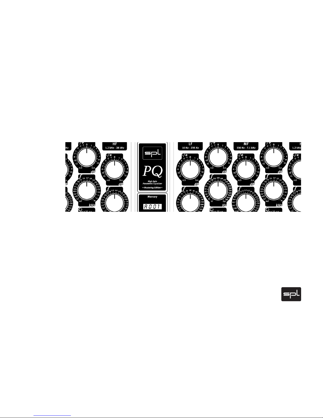
> PQ Mastering Equalizer

2
Analog, dual-channel fi ve-band parametric equalizer
Owner‘s Manual V 1.4, 9/2003
Software version 240H
R & D: Wolfgang Neumann
The information in this document has been carefully verifi ed and is assumed to be
correct. However Sound Performance Lab (SPL) reserves the right to modify the
product describe d in this manual at any time. Changes without notice. This document
is the property of SPL and may not be copied or reproduced in any manner, in part or
full without the authorization of SPL.
Limitations of Liability:
In no event will SPL be liable for any damages, including loss of data, lost profi ts,
cost of cover or other special, incidental, consequential or indirect damages arising
from the use of the unit, however caused and on any theory of liability. This limitation will apply even if SPL or an authorized dealer has been adviced of the possibility
of such damage.
Sound Performance Lab
SPL electronics GmbH
P.O . B ox 12 27, D- 41368 Niederkruechten, Germany
Phone +49 2163 983 40
Fax +49 2163 983 420
Email: info@soundperformancelab.com
www.soundperformancelab.org
© 2003 SPL electronics GmbH
All rights reserved. Technical specifi cations and appearance are subject to change
without notice.
PQ Mastering Equalizer, Model 2050 Owner‘s Manual

3
Content
Introduction 3
Installation 4
Techn ol og y 5
Key Functions 6
Channel Control Elements 8
Techn ic al Sp ecifi cations 10
Warrant y 11
Introduction
Dear customer,
thanks for using the PQ Mastering Equalizer. We wish you have as much fun working
with it as we had during the development of this extraordinary equalizer.
Supplied parts
• PQ Mastering Equalizer
• External power supply transformator including both power cords
• Owner’s Manual
Key features
• Pure analog, discrete Class A equalization circuitry
• Digital storability and total recall with motorized controls and 800 presets
• Constant Q and proportional Q modes, selectable per fi lter band
• 124 V internal operating voltage for clean, consistent audio
• Discrete SPL SUPRA op-amps with 150 dB dynamic range
• Channel link mode for stereo applications
• Master/slave unit link mode for surround applications or subgroup processing
allows remote control of up to four PQs via optional remote unit (still in
development)
• As with all SPL products, the PQ is conceived, designed and hand-built in Germany

4
Installation
BEFORE SWITCHING ON POWER SUPPLY AND PQ, THE PQ MUST BE CONNECTED TO
THE POWER SUPPLY WITH THE SUPPLIED MULTICORE LEAD. PAY ATTENTION TO A
SECURE CONNECTION.
The PQ and the external power supply should be situated away from heat sources
and direct sunlight. P Q and power supply need suffi cient air circulation. Avoid installation in environments exposed to vibrations, dust, heat, cold, moisture or electrical
and magnetic fi elds.
Do not install the unit in proximity to power amplifi ers or digital processors. You
may consider placing it in a rack containing other analog gear. Such placement can
prevent interference from Word Clock, Smpte, MIDI, etc.
• Do not open the case. You may risk electric shock and may damage your equipment.
• Leave repairs and maintenance to a qualifi ed service technician. Should foreign
objects fall inside the case, contact your authorized dealer or support person.
• To avoid electric shock or fi re hazards do not expose your unit to rain or dampness.
• In case of lightning unplug the power supply. Please unplug the cable by pulling on
the plug only; never pull on the cable.
• Never force a switch or knob.
• To clean the case use a lint-free cloth. Avoid cleaning agents as they may damage
the chassis.
• Please support the back of the unit whenever it is being mounted into a 19 inch
rack (especially important when touring).
Setting the appropriate supply voltage
The appropriate supply voltage (115 V/230 V) must be set on the rear panel of the
external power supply. The fuse block (lef t from the power cord socket) can be
inserted in two positions to meet your countr y‘s power requirements. Refer to the
marks on the fuse block (triangles for both voltages) and insert the block with the
appropriate triangle pointing to the white line on the fuse block case.
The power supply is fi tted with 3,5 A fuses, slow blow.
Power-up sequence
It takes about four seconds until the power-up sequence is completed. During this
procedure, all potentiometers will move to the center (12 o’clock) position and a test
routine checks all 32 relays (you will notice 32 clearly audible relay clicks), while the
display indicates “SETP ” ( “setup”).
After fi nishing the power-up sequence the display shows A000 and the unit is ready
to operate.
Ground Lift switch
A switch labelled „GND LIF T“ is placed on the rear panel of the power supply. It ser ves
to eliminate hum problems. This switch physically separates chassis ground from AC
ground; GND LIFT is activated (=chassis ground separated) when the switch points
downwards.
 Loading...