

Page 1

Hermes
Mastering Router
Manual
Page 2

Content
Hermes
Version 1.1 – 12/2018 2
Package Contents 2
Product Registration 2
Introduction 3
The routing matrix for the mastering studio 3
Technical Aspects 4
120 Volt Technology 4
120 Volt Technology – Diagram 5
Installation 6
Voltage Selection 6
First Steps 6
Cabling: Rear Side 7
XLR inputs and output 7
DB25 inputs and outputs 7
Ground Lift switch to avoid ground loop 7
1 Sends A-D (left) 10
2 Sends A-D (right) 10
3 Returns A-D (left) 10
4 Returns A-D (left) 10
5 Sends / Returns E-H (left) 10
6 Sends / Returns E-H (right) 10
7 Input / Output (left) 11
8 Input / Output (right) 11
Pairing Hermes and DMC 11
Page 3

Control Elements 12
1 Insert buttons A-H 14
2 New [Delete] 14
3 Store [Hold 2s to Label] 14
4 Preset 1 [< ABC] 14
5 Preset 2 [ABC >] 14
6 Preset 3 [123 >] 15
7 All Bypass [Enter] 15
8 Main-Display 15
9 Position Parallel Mix 1 15
10 Position Parallel Mix 2 15
11 Display for the position of the Parallel Mix 16
12 Parallel Mix 1 On / Off 16
13 Parallel Mix2 On / Off 16
14 Parallel Mix 1 Gain-Control 16
15 Parallel Mix 2 Gain-Control 16
16 Parallel Mix 1 Gain-Control On / Off 16
17 Parallel Mix 2 Gain-Control On /Off 16
18 Parallel Mix 1 Blend-Control 16
19 Parallel Mix 2 Blend-Control 16
Content
M/S with Hermes & Gemini 17
Pairing Hermes and Gemini 17
Specications 18
Measurements 18
Security Advices 19
Notes on Environmental Protection 20
Contact 21
Copy template settings 22
Page 4

Version 1.1 – 12/2018
Developer: Wolfgang Neumann
This manual includes a description of the product but no guarantee as for specific characteristics or successful results.
Unless stated otherwise, everything herein corresponds to the technical status at the
time of delivery of the product and user manual by SPL electronics GmbH.
The design and circuitry are under continuous development and improvement.
Technical specifications are subject to change.
Package Contents
Hermes Mastering Router
Power cord
Manual
The Hermes Mastering Router is available in different colors.
Black: Model 1620
Red: Model 1624
All Black: Model 1623
Do consider keeping the original packaging. It can come in very useful whenever you need
to transport your gear. If there is ever the need to send it in for repair, the original packaging guarantees a safe shipment..
Product Registration
Register your device to get useful information concerning the product. On the front page
of this manual you will find a QR code, which includes the link to the registration form and
automatically fills in the serial number and product name into the form. Alternatively you
can also call up the online form with your internet browser via the following link:
https://spl.audio/register
2
Page 5

Introduction
The routing matrix for the mastering studio
The Hermes Mastering Router revolutionizes Mastering.
With Hermes, it is possible to route an audio signal through up to eight dual-channel processors in any order.
User denable presets allow the comparison of complex processing chains with just a ip
of a button.
In addition, Hermes has two integrated parallel mix stages that work with any of the eight
processors allowing for comparison of two compressors with different parallel mix settings. The parallel mix stages are stored with the processing chains.
Hermes routing is entirely passive using gas-capsuled and gold-plated high-end relays.
All active electronics like the in and output stages and the Parallel Mixes use SPL‘s proprietary and unequaled 120V DC audio rail.
Hermes speeds up the workow in mastering in ways that were previously extremely difcult, and makes the most out of your existing mastering gear.
Repatching to hear a simple change is a thing of the past with Hermes – you can change
processor sequences on the y, store them, and compare settings instantly. All with real
switches, relays and no software application
You will rediscover your processors, because the possible combinations and Parallel Mix
stages open up new horizons.
The Hermes Mastering Router was designed, developed and manufactured in Germany.
3
Page 6

Technical Aspects
120 Volt Technology
SPL‘s goal was to push analog signal processing to the limits. That‘s why we combined
the best possible components with a high-grade optimized circuit design.
We have been using the in-house developed 120 Volt technology - the highest-ever operating voltage used for audio applications - in all our products from the Mastering series
for years. Some of the most highly respected Mastering studios today revolve around
SPL consoles and signal processors from our Mastering series (Bob Ludwigs Gateway
Mastering & DVD in the USA, Simon Heyworth‘s Super Audio Mastering in the UK, Galaxy
Studios in Belgium, and the legendary Wisseloord in the Netherlands, for instance).
The 120 Volt technology is based on op-amps developed internally by SPL‘s co-founder
and Chief Developer Wolfgang Neumann. The Hermes Mastering Router features the
most advanced generation of these op-amps. They boast with even better tech specs
thanks to the thermal behavior optimization they underwent under the hands of Bastian
Neu.
Ultimately, the supply voltage is key for the overall dynamic response of a processor.
Voltage is to an electrical circuit what cylinder capacity is to an internal combustion
engine:
You can‘t replace cylinder capacity with anything else, except more cylinder capacity.
4
Page 7
Technical Aspects
-115
THD&N
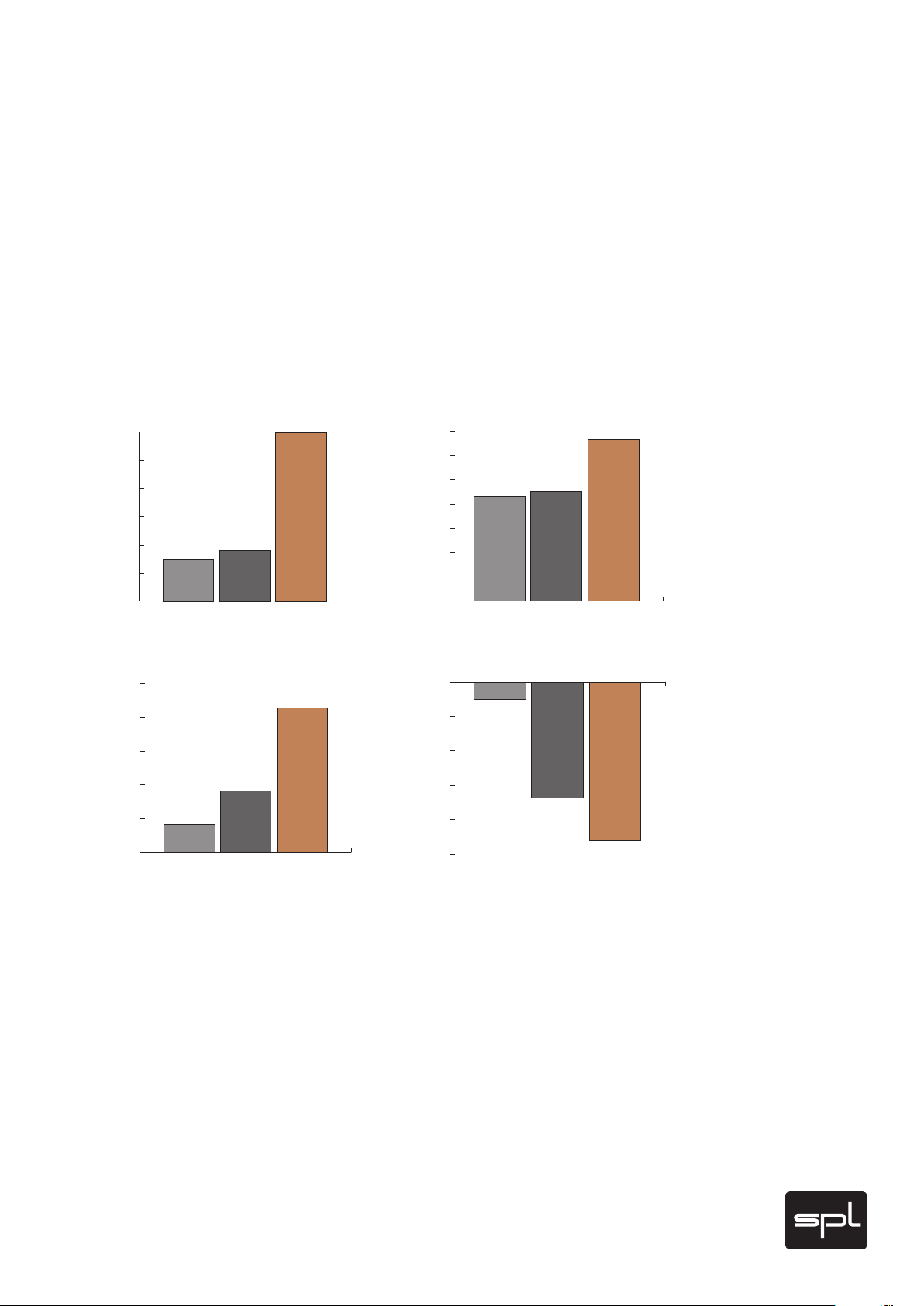
120 Volt Technology - Diagrams
These diagrams clearly show the advantages of our 120-volt technology in comparison to
other circuits with a lower operating voltage. The direct relation between operating level
and maximum level is fundamental for the classification: the higher the operating level,
the higher the maximum level a circuit can handle. And since virtually all essential acoustic and musical parameters depend on this relation, a higher operating voltage also has a
positive impact on the dynamic range, distortion limit and signal-to-noise ratio. The result
is a clearly more laid-back and natural sound with less unpleasant coloring.
Do bear in mind that dB scales do not represent linear but rather exponential increases. A
3 dB increase corresponds to doubling the acoustic power, +6 dB correspond to twice the
sound pressure level, and +10 dB correspond to twice the perceived loudness.
Volt
120
100
80
60
40
20
0
dBu Dynamic Range
145
140
135
130
125
120
30 V
+/- 15 Volt +/- 18 Volt +/- 60 Volt
124,2
OPA 134@30 V OPA 134@36 V SPL-OP@120 V
Operational Voltages
120 V
36 V
141,4
129,1
dBu
35
30
25
dBu
-105
-107
-109
-111
-113
20
15
10
5
0
21,5
OPA 134@30 V OPA 134@36 V SPL-OP@120 V
TL 071@30 V OPA 134@36 V SPL-OP@120V
106
Maximum Levels
33,2
22,5
111,7
114,2
When it comes to volume, the 120-volt technology exhibits a performance that is twice
that of common components and circuits, in regard to maximum level and dynamic range,
with values that are approximately 10 dB higher. THD measurements of the SPL op-amps
show a difference of more than 3 dB compared to the OPA134 at 36 V — in terms of sound
pressure level, that corresponds to an improvement of more than 50%.
The operating level most commonly used for audio equipment is 30 volts.
5
Page 8

Installation
Voltage Selection
Before connecting the Hermes Mastering Router to the mains, make sure that the voltage
selection corresponds to the values of your local power grid (230 or 115 volts). Inside the
power connector, to the right, next to the on/off switch, there is an opening that displays
the voltage selected. If the voltage indicated does not correspond to the one required,
change it by following this procedure:
Open the power connector lid with a small screwdriver (use the tiny slots on the right hand
side). Use the screwdriver to lever the red fuse holder from above until you can grab it.
Take the fuse holder out and replace the fuse with one corresponding to the local power
grid specifications. You can find the adequate values on the rear of the unit or on page 16
of this user‘s manual. Turn the fuse holder around 180 degrees and place it back again.
When you close the lid again, you should see the correct voltage displayed in the opening.
On the product site on our website (http://hermes.spl.audio) you will find a video concerning the topic “Changing the mains voltage”. If you ever have to exchange a fuse, we
recommend the video “Exchange defective fuses”.
First Steps
Before turning on the Hermes Mastering Router you must first connect the included 3-pin
power cord to the 3-pin IEC socket. The transformer, power cord and IEC socket all comply
to the VDE, UL and CSA regulations.
The Hermes Mastering Router should not be installed in close proximity to equipment
that emits magnetic fields or emanates heat. Avoid exposure to heat, moisture, dust, and
vibrations. Do not install the Hermes Mastering Router close to any power amps or digital processors. Instead, install it in a fully “analog rack” where any interferences can be
avoided (Word Clock, SMPTE, MIDI etc.).
The unit should be powered off before connecting or disconnecting any cables or equipment to it.
Use the On/Off switch on the rear panel to turn the unit on or off. The illuminated red LED
in the middle of the front panel indicates the unit‘s operating status. The On/Off switch
was placed on the rear panel to avoid any emissions due to voltage-carrying conductors
running across the unit and affecting sound. When powering on or off, there‘s no need
to observe a specific sequence regarding the connected devices. However, like with any
audio signal chain, power amplifiers should always be powered on last and powered off
first. The Hermes Mastering Router can be powered on and off with the use of a circuit
breaker, as long as the total load does not exceed the rating of the latter.
After switching on the device, the name “Hermes” and the installed software version
appears on the display. After that, all buttons light up left to right, in the order from top to
bottom, starting with “On 1”. Afterwards, the last selected configuration is loaded.
6
Page 9

Cabling: Rear Side
XLR inputs and outputs
We used exclusively Switchcraft/Neutrik XLR input and output plugs to guarantee perfect
connectivity in the studio. They provide an optimal connection thanks to their electromechanical design and large contact surface.
The image shows the XLR connectors pinout. They are balanced and have three conductors or wires. Conductor 2 (Pin 2) corresponds to the (+) or hot Signal.
In case an unbalanced connection is necessary, the correct polarity of the conductors
needs to be observed.
DB25 in and output connectors
The image shows the assignment of the DB25 connectors. The pin assigment corresponds
to Tascam standard, (AES/EBU). The inputs (Returns) are located on positions 1-4. The
outputs (Sends) on positions 5-8.
Returns
1 2 3 4 1 2 3 4
GCHGCH
13
25
G=GROUND (GND), C=COLD (-), H=HOT (+)
GCHGCH GCH GCH GCH GCH
Sends
1
14
Ground Lift switch to avoid ground loops
On the rear panel of the Hermes Mastering Router (see page 8) is also a „GND LIFT“
(Ground Lift) switch to avoid any ground loops. Ground loops take place when gear connected in the same network have different potentials
The GND LIFT switch disconnects the equipment ground from the service ground to avoid
such problems. The Ground Lift function is activated (= equipment ground disconnected)
when the switch is depressed.
7
Page 10

Cabling: Rear Side
10
9
1 Sends A-D (left)
10
9
7
8
2 Sends A-D (right))
3 Returns A-D (left)
4 Returns A-D (right)
5 Sends / Returns E-H (left)
6 Sends / Returns E-H (right)
7 Input / Output (left)
8 Input / Output (right)
9 Ground-Lift (see details on page 7
10 Voltage (see details on page 6)
8
Page 11

Cabling: Rear Side
4
3
6
5
We also provide a Screenshow video manual on the product page on our website:
https://hermes.spl.audio
9
Page 12

Rear Side: Connections
1 Sends A-D (left)
In the Sends A-D (left) section, Hermes provides four balanced output jacks. These are
male XLR jacks. These outputs send the signal for the left input channels of connected
devices.
2 Sends A-D (right)
In the Sends A-D (right) section, Hermes provides four balanced output jacks, male XLR.
These outputs send the signal for the right inputs of connected devices.
3 Returns A-D (left)
In the Returns A-D (left) section, Hermes provides four balanced input jacks. These are
female XLR jacks. These outputs receive the signal for the left output channels of connected devices.
4 Returns A-D (right)
In the Returns A-D (right) section, Hermes provides four balanced input jacks, male XLR.
These inputs receive the signal of the right outputs of connected devices.
5 Sends / Returns E - H (left)
For the Sends / Returns (left) a DB25 connector is provided. The four Sends send the signal for the left inputs of connected devices. The four Returns receive the signal of the left
outputs of connected devices. The pin assigment corresponds to Tascam standard (see
page 7). To connect external devices, you should use a cable with four XLR, male and four
XLR, female. The inputs (Returns) are located on positions 1-4. The outputs (Sends) on
positions 5-8.
6 Sends / Returns E - H (right)
For the Sends / Returns (right) a DB25 connector is provided. The four Sends send the
signal for the right inputs of connected devices. The four Returns receive the signal of the
right outputs of connected devices. The pin assigment corresponds to Tascam standard
(see page 7). To connect external devices, you should use a cable with four XLR, male and
four XLR, female. The inputs (Returns) are located on positions 1-4. The outputs (Sends)
on positions 5-8.
10
Page 13

Rear Side: Connections
7 Input / Output (left)
The signal, which is supposed to be sent to the left channel of all devices connected to
the inserts, is sent to the input (left), XLR, female. After the insert chain, this signal is outputted through the output (left), XLR, male. With this input / output, you can (for example)
pair Hermes to the main insert of a mastering console like the SPL DMC Mastering Console
or a DAW.
8 Input / Output (right)
The signal, which is supposed to be sent to the left channel of all devices connected to
the inserts, is sent to the input (right), XLR, female. After the insert chain, this signal is
outputted through the output (right), XLR, male
Pairing Hermes and DMC
11
Page 14

Control Elements
8
1
2
1 Insert-Taster A-H
2 New [Delete]
3 Store [Hold 2s to Label]
4 Preset 1 [< ABC]
5 Preset 2 [ABC >]
3
4 5
6
7
9
10
11
6 Preset 3 [123 >]
7 All Bypass [Enter]
8 Main-Display
9 Position Parallel Mix 1
10 Position Parallel Mix 2
11 Display for the position of the Parallel Mix
12
Page 15

Control Elements
12
18
12 Parallel Mix 1 On / Off
13 Parallel Mix 2 On / Off
14 Parallel Mix 1 Gain Control
14
16 17
19
13
15
15 Parallel Mix 2 Gain Control
16 Parallel Mix 1 Gain Control On / Off
17 Parallel Mix 2 Gain Control On / Off
18 Parallel Mix 1 Blend Control
19 Parallel Mix 2 Blend Control
We also provide a Screenshow video manual on the product page on our website:
https://hermes.spl.audio
13
Page 16

Control Elements
1 Insert buttons A-H
With the insert buttons A to H, you can activate or deactivate the respective Insert.
Furthermore, the order of the selection corresponds with the order of the inserts of the
mastering chain. If you (for example) first activate insert D and then insert B after wards,
this will also correspond to the signal flow, which means that the signal is firstly sent to
insert D and then to inser t B.
2 New [Delete]
By activating the NEW button, you can create a new processing chain. All Inserts, which
were previously activated, will be deactivated and the order which was previously set
with the inserts and the linkings of the Parallel Mix are deleted. Now you can create a
completely new processing chain.
The button has a further function on a second level (Label Mode). In this mode you can
delete letters and characters with the DELETE button.
3 Store [Hold 2s to Label]
You can store a processing chain with the STORE button. If you press the STORE button, it
lights up red and the Preset buttons start to blink orange. In this mode, a storage space
for the active inser t chain can now be selected with the Preset button.
On the second functional level, this button activates the Label Mode. To switch to the Label
Mode, press the button for two seconds. If the Label Mode is active, the STORE button
blinks red and the insert button orange. If you now select an insert, it can be labeled. The
button of the selected insert now light up orange and the STORE button keeps on blinking
red. If you press the STORE button again, you can end the Label Mode
4 Preset 1 [< ABC]
With the button 1 in the Preset section, you can activate or store Preset 1.
On the second functional level, this button enables the selection of letters in Label Mode.
The selection runs in the opposite direction compared to the normal order of letters, hence
Z, Y, X, …
5 Preset 2 [ABC >]
With the button 2 in the Preset section, you can activate or store Preset 2.
14
On the second functional level, this button enables the selection of letters in Label Mode.
The selection runs in the normal order of letters, hence A, B, C, …
Page 17

Control Elements
6 Preset 3 [123 >]
With the button 3 in the Preset section, you can activate or store Preset 3.
On the second functional level (Label Mode), this button enables the selection of letters
and numbers. The selection runs in the normal order of letters, hence A, B, C, …
7 All Bypass [Enter]
When the ALL BYPASS button is active, the audio signal is not routed through the insert
chain, but is sent from the input of Hermes directly to the output.
On the second functional level (Label Mode), this button enables the selection of a letter,
number or character. This takes the cursor to the next position on the Main Display.
8 Main-Display
In normal operation, the active processing chain is displayed on the Main Display. If, for
example, the number 6 is displayed at insert D, it means that insert D is the sixth insert
in the current insert chain. Furthermore, helpful information is shown in the display. The
individual inserts can be labeled, which is shown when they are activated. If, for example,
an SPL IRON Mastering Compressor is connected to insert D, its name can be labeled at
this insert with the Label Mode. Another very helpful information is the little dot at the
lower right hand corner of a number, when a processing chain is shown. This dot visualizes the assignment of a Parallel Mix. If (for example) there is a little dot at insert D, it
means that this insert D assigned to a Parallel Mix stage.
9 Position Parallel Mix 1
With this button, the position/assignment of the Parallel Mix stage 1 is determined. When
pressing this button for the first time, the Parallel Mix 1 is assigned to the first insert in
the chain. When pressing it for the second time it is assigned to the second. And so on.
Until you ran through the complete insert chain. The position of the Parallel Mix is shown
in the Display (11) .
10 Position Parallel Mix 2
With this button, the position/assignment of the Parallel Mix stage 2 is determined. The
basic functioning is equivalent to the functioning of the button for Parallel Mix 1, but of
course relating to the Parallel Mix 2.
15
Page 18

Control Elements
11 Display for the position of the Parallel Mix
In this display, the assignment of the Parallel Mix stages is shown.
12 Parallel Mix 1 On / Off
With this button, you can turn the Parallel Mix 1 on or off.
13 Parallel Mix2 On / Off
With this button, you can turn the Parallel Mix 2 on or off.
14 Parallel Mix 1 Gain Control
With this detended potentiometer, you can increase or attenuate the level of Parallel Mix
1 up to 10 dB..
15 Parallel Mix 2 Gain Control
With this detended potentiometer, you can increase or attenuate the level of Parallel Mix
2 up to 10 dB.
16 Parallel Mix 1 Gain Control On / Off
With this button, you can activate or deactivate the Parallel Mix Gain Control 1 (14).
17 Parallel Mix 2 Gain Control On /Off
With this button, you can activate or deactivate the Parallel Mix Gain Control 2 (15).
18 Parallel Mix 1 Blend Control
With this detended potentiometer, you can blend between the device connected to an
insert ( Wet) and the signal which is located at the input of this insert stage (Dry). This gives
you the opportunity (for example) to use a compressor more intensively, but only mix this
signal with the original signal and thereby maintain a part of the original transients.
16
19 Parallel Mix 2 Blend Control
The Parallel Mix 2 Blend Control operates equivalent to the Parallel Mix 1 Blend Control,
but for the Parallel Mix 2.
Two Parallel Mix stages are ideal, because this way you can switch between various constellations (different devices) and mixing ratios (one device with different Dry/Wet ratios).
Page 19

Pairing Hermes and Gemini
M/S with Hermes & Gemini
Hermes and Gemini (Mastering M/S Processor) operate in their complete range of functions as stand-alone devices. A pairing of Hermes and Gemini enables lots of further
possibilities.
If the M/S Encoder and Decoder stages of Gemini are each paired with an insert of Hermes,
it is possible to freely choose a position for the M/S Encoder and Decoder within the processing chain. This way, it is possible (see image below) to place the M/S Encoder on the
third position, an equalizer on the fourth to use it for separate processing of the mid and
side signal and then use the M/S Decoder stage of the Gemini on the fifth position to
generate an L/R stereo signal. If you now like to additionally use a compressor, as a further device for M/S processing, you can place it on position 5 and the M/S Decoder stage
would thus move to position 6.
1
-
1
-
2
L
-
R
2
L
-
R
3
L M
M/S
Encoder
R S
3
L M
M/S
Encoder
R S
4
Equalizer
4
Equalizer
M
Decoder
S
M
Kompressor
S
5
M/S
5
L
R
M
S
6
-
6
M/S
Decoder
7
L
-
R
7
L
-
R
8
L
-
R
8
L
-
R
17
Page 20

Specications
Measurements
Inputs
Max. Input Level ...................................................................... + 32,5 dBu
Max. Input Level (Parallel Mix, Gain active) ............................... + 28 dBu
Input Impedance ...................................................................... 20 kOhm (bal.)
Outputs
Max. Output Level .................................................................... + 32,5 dBu
Output Impedance .................................................................... ‹ 600 Ohm (bal.)
Noise (A-weighted) ..................................................................... - 121 dBu
Noise (A-weighted, Parallel Mix active) ........................................ - 104 dBu
Noise (A-weighted, Parallel Mix, Gain active) ............................... - 102 dBu
Crosstalk (at 1 kHz at 0 dBu) ....................................................... › -130 dB
Crosstalk (at 1 kHz at 0 dBu Parallel Mix active) ........................... › -110 dB
Crosstalk (at 1 kHz at 0 dBu Parallel Mix, Gain active) ................. › -80 dB
THD & N (at +20dBu) ..................................................................... › -112 dBu
Common-Mode-Rejection (at 0 dBu) .............................................. › -75 dB
Transmission Bandwidth: 10 Hz-200 kHz
10 Hz = -0,12 dB; 100 kHz = -0,3 dB; 200 kHz = -1,2 dB
Power Consumption: ..................................... 0,17 Amp, 230V/50Hz, 30 Watt, 37,6 VA
0,34 Amp, 115V/60Hz, 30 Watt, 37,6 VA
Fuses ........................................................... 230 V/50 Hz: 1 Amp
115 V/60 Hz: 2 Amp
18
Dimensions
Standard EIA 19 Inch Housing/2U ....... 482 x 88 x 300 mm / ca. 19" x 3,5" x 11,8"
(front panel excl.)
Weight ............................................... 9 kg / 19,84 lb
Page 21

Security Advices
Connections
Only use the connections as described. Other connections can lead to health risks and
damage the equipment.
Water and humidity
Do not use this device anywhere near water (for example in a bath room, a damp cellar,
near swimming pools, or similar environments). Otherwise your are dealing with an
extremely high risk of fatal electrical shocks!
Insertion of objects or fluids
Be careful to not insert any object into any of the chassis openings. You can otherwise
easily come into contact with dangerous voltage or cause a damaging short circuit. Never
allow any fluids to be spilled or sprayed on the device. Such actions can lead to dangrous
electrical shocks or fire!
Ventilation
The vent openings on the unit are meant to avoid the Hermes from overheating. You
should never cover nor block these openings.
Power Supply
Power the unit exclusively with the voltage rating specified on the unit. In case of doubt,
contact your local dealer or electric provider. Disconnect the unit from the electric power
grid if you are not going to use it for a long period of time. Unplug the power chord from
the mains to cut power supply to the unit. Always make sure that the mains plug is easily
accessible.
Opening the unit
Simply put: DON‘T, if you are not a certified SPL technician or engineer. Really: Do not
open the device housing, as there is great risk you will damage the device, or – even after
being disconnected – you may receive a dangerous electrical shock!
Cord protection
Make sure that your power and audio signal cords are arranged to avoid being stepped on
or any kind of crimping and damage related to such event. Do not allow any equipment or
furniture to crimp the cords. Power connection overloads: Avoid any kind of overload in
connections to wall sockets, extension or splitter power cords, or signal inputs. Always
keep manufacturer warnings and instructions in mind. Overloads create fire hazards and
risk of dangerous shocks!
Lightning
Before thunderstorms or other severe weather, disconnect the device from wall power;
do not do this during a storm in order to avoid life threatening lightning strikes. Similarly,
before any severe weather, disconnect all the power connections of other devices and
antenna and phone/network cables which may be interconnected so that no lightning
damage or overload results from such secondary connections.
19
Page 22

Security Advices
Controls and switches
Operate the controls and switches only as described in the manual. Incorrect adjustments
outside safe parameters can lead to damage and unnecessary repair costs. Never use the
switches or level controls to effect excessive or extreme changes.
Repairs
Unplug the unit from all power and signal connections and immediately contact a qualified technician when you think repairs are needed – or when moisture or foreign objects
may accidentally have reached inside the housing, or in cases when the device may have
fallen and shows any sign of having been damaged. This also applies to any situation in
which the unit has not been subjected to any of these unusual circumstances but still is
not functioning normally or its performance is substantially altered. In cases of damage
to the power supply and cord, first consider turning off the main circuit breaker before
unplugging the power cord.
Replacement/substitute parts
Be sure that any service technician uses original replacement parts or those with identical
specifications as the originals. Incorrectly substituted parts can lead to fire, electrical
shock or other dangers, including further equipment damage. Safety inspection: Be sure
always to ask a service technician to conduct a thorough safety check and ensure that the
state of the repaired device is in all respects up to factory standards.
Cleaning
Do not use any solvents, as these can damage the chassis finish. Use a clean, dry cloth (if
necessary, with an acid-free cleaning oil). Disconnect the device from your power source
before cleaning
Notes on Environmental Protection
At the end of its operating life, this product must not be disposed of with regular
household waste but must be returned to a collection point for the recycling of electrical
and electronic equipment. The wheelie bin symbol on the product, user‘s manual and
packaging indicates that. The materials can be reused in accordance with their markings.
Through reuse, recycling of raw materials, or other forms of recycling of old products,
you are making an important contribution to the protection of our environment. Your local
administrative office can advise you of the responsible waste disposal point.
WEEE Registration: 973 349 88.
20
Page 23

SPL electronics GmbH
Sohlweg 80
41372 Niederkrüchten
Fon +49 (0) 21 63 98 34 0
Fax +49 (0) 21 63 98 34 20
E-Mail: info@spl.audio
Follow us on our Blog, Youtube, Twitter, Instagram and Facebook:
Website & Blog: spl.audio
Facebook: facebook.spl.audio
Instagram: instagram.spl.audio
Twitter: twitter.spl.audio
Contact
Videos: youtube.spl.audio
© 2018 SPL electronics GmbH
This document is the property of SPL and may not be copied or reproduced in any manner, in part or fully, without prior authorization by SPL. Sound Performance Lab (SPL)
continuously strives to improve its products and reser ves the right to modify the product described in this manual at any time without prior notice. SPL and the SPL Logo are
registered trademarks of SPL electronics GmbH. All company names and product names
in this manual are the trademarks or registered trademarks of their respective companies.
Declaration of CE Conformity
The construction of this unit is in compliance with the standards and regulations of the
European Community.
21
Page 24

Engineer:
Track(s)/Groups:
Date:
Copy Master: Recall Settings
Artist:
Album:
Titel:
 Loading...