

Page 1
Manual
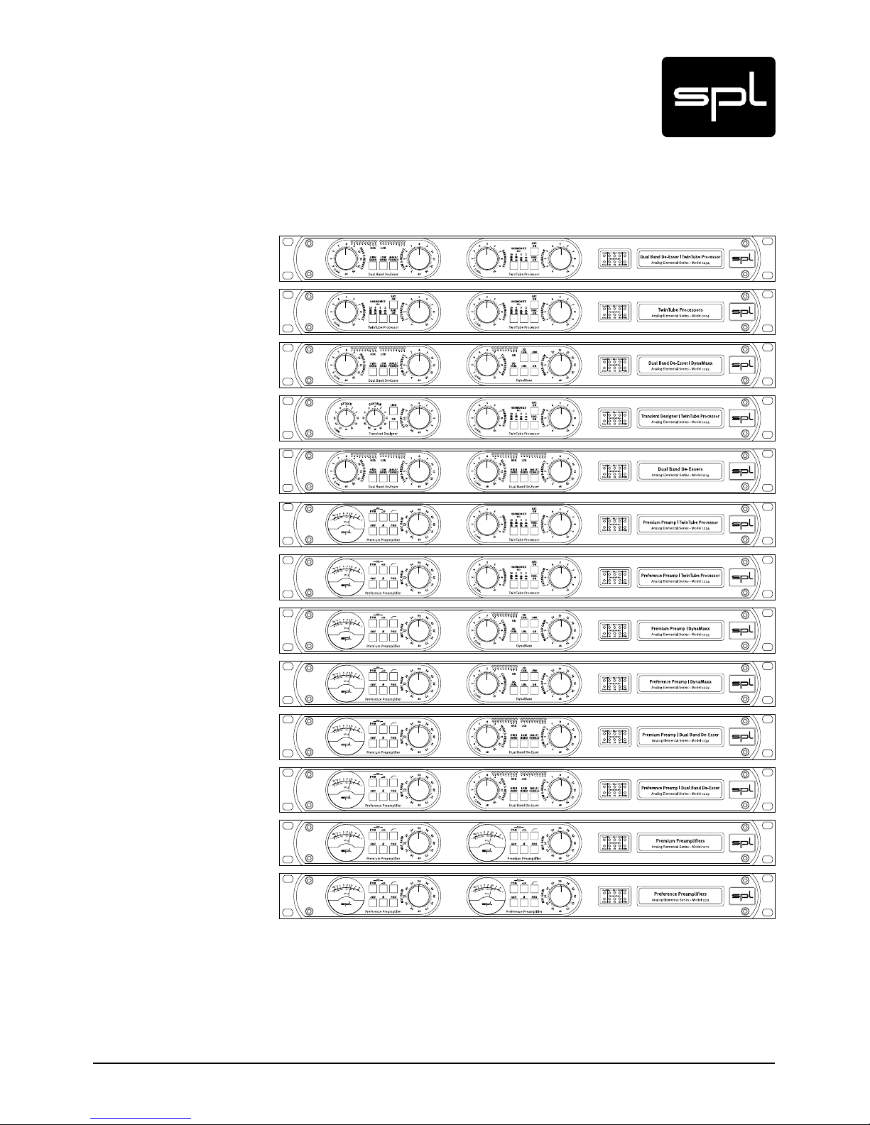
Twin Module Series featuring the modules
Premium Mic Pre, Preference Mic Pre, Dual-Band De-Esser, DynaMaxx, Transient Designer und TwinTube
Analog Elemental Series
Models 1211, 1212, 1214, 1219, 1223, 1224, 1229, 1233, 1234, 1239, 1254, 1293, 1294
Page 2

2
Analog Elemental Series
Content
Manual Analog Elemental Series 6
CE Conformity 6
Notes on Environmental Protection 6
Contact 6
Symbols and Notes 6
Important Security Advices 7
Scope of Delivery and Packaging 8
Hook Up 8
Placement 8
Introduction 8
The Analog Elements 8
Die Signalprozessoren der zweiten Generation 9
Concept and Categories of the Analog Elemental Series 9
Dual-Channel Preamplifiers 9
Channel Strips 9
Processing Units 10
Optional Features 11
Information on Transformers 11
Common Technical Specifications 11
Dimensions and Weight 11
Rear Panel | Wiring Diagram 12
Rear Panel | Versions 13
Rear Panel 1 13
Rear Panel 2 13
Rear Panel 3 13
Optional Converter: Wiring Diagram 13
Rear Panel | Connections and Switches 14
Signal Connections 14
Input and Output Electronics 14
XLR sockets 14
Balanced connections 14
Unbalanced connections 14
Power connection and fuse 15
Voltage Selector 15
Power switch 15
GND Lift 15
Channel Strip Switch (Ch. 1 OUT = Ch.2 IN) 15
Page 3

3
Analog Elemental Series
Content
The Modules 16
Premium Mic Pre | Introduction 16
Features 16
Premium Mic Pre | Control Elements 16
Mic Gain 16
About Leveling 17
VU Meter 17
PPM 17
-10 17
48 V Phantom Power Supply 18
Pad 18
Phase Reverse 18
High-Pass Filter 18
Premium Mic Pre | Technology 19
Triple Stage Preamp 19
Stage 1 – The Input Transformer 19
Stage 2 – The Discrete Differential Amplif ier 19
Stage 3 – The Instrumentation Amplifier 20
Foil and Styroflex Capacitors 20
Output Stages 20
Premium Mic Pre | Technical Specifications 20
Audio 20
Input 20
Output 20
Control Elements 20
Premium Mic Pre | Block Diagram 21
Preference Mic Pre | Introduction 22
Main Features 22
Preference Mic Pre | Control Elements 22
Mic Gain 22
About Leveling 22
VU Meter 23
PPM 23
-10 dB 23
48-V-Phantom Power Supply 23
Phase Reverse 24
High-Pass Filter 24
Preference Mic Pre | Technology 25
SSM 2019 25
Servo Drive Design 25
Foil And Styroflex Capacitors 25
Output 25
Preference Mic Pre | Technical Specifications 26
Audio 26
Input 26
Output 26
Control Elements 26
Preference Mic Pre | Block Diagram 27
Page 4

4
Analog Elemental Series
Content
Dual-Band De-Esser | Introduction 28
The Dual-Band De-Esser 28
Dual-Band De-Esser | Control Elements 28
HI-Band On, Low-Band On 28
Low S-Reduction 29
High S-Reduction 29
Male/Female 29
Signal-LED (SIG.) 29
Dual-Band De-Esser | Technical Specifications 30
Audio 30
Output 30
Control Elements 30
Dual-Band De-Esser | Block Diagram 31
DynaMaxx | Introduction 32
DynaMaxx | Control Elements 32
Compression 32
Make-Up Gain 33
Gain Reduction LEDs 33
DE-COM. (De-Compression) 33
FX Com. (Effect Compression) 34
Lim. (Limiter) 34
On 34
Link 35
Signal-LED (SIG.) 35
DynaMaxx | Technology 35
Why are conventional compressors unsatisfactory? 35
Full-Band versus Multi-Band 36
Attack Time Automation 36
Release Time Automation 37
Threshold And Ratio 37
DynaMaxx | Technical Specifications 38
Audio 38
Input 38
Output 38
DynaMaxx | Block Diagramm 39
Page 5

5
Analog Elemental Series
Content
Transient Designer | Introduction 40
Transient Designer | Control Elements 40
On 40
Attack 40
Sustain 41
Output Gain 41
Link Mode 41
Signal LED 41
Transient Designer | Applications 42
Drums & Percussions 42
Guitars 43
Bass: Staccato vs. Legato 43
Ambience 43
Keyboards & Sampler 43
Post Production 43
Mastering 43
Transient Designer | Technical Specifications 44
Audio 44
Input 44
Outputs 44
Transient Designer | Block Diagram 45
TwinTube | Introduction 46
TwinTube | Control Elements 46
HAR. ON/SAT. ON 46
HARMONICS Control 46
HARMONICS Switch 47
SATUR ATION Control 47
Signal LED 47
TwinTube | Applications 47
Vocals 47
Acoustic Guitars 47
TwinTube | Measurements 48
TwinTube | Technical Specifications 50
AUDIO 50
AUDIO – CUMUL ATIVE (Harmonics and Saturation Stage) 50
TwinTube | Block Diagram 51
Page 6
6
Analog Elemental Series
Symbols and Notes
Version 1.0 – 6/2012
Developers: Wolfgang Neumann, Enzo Triolo, Jens Gronwald
This manual contains a description of the product. It in no way represents a guarantee of
particular characteristics or results of use. The information in this document has been carefully compiled and verified and, unless otherwise stated or agreed upon, correctly describes
the product at the time of packaging with this document.
Sound Performance Lab (SPL) continuously strives to improve its products and reserves the
right to modify the product described in this manual at any time without prior notice.
© 2012 SPL electronics GmbH. All rights reserved. This document is the property of SPL and
may not be copied or reproduced in any manner, in par t or fully, without prior authorization by
SPL. Names of other companies and their products are trademarks of their respective owners.
CE Conformity
The construction of the Analog Elemental Series is in compliance with the
standards and regulations of the European Community.
Notes on Environmental Protection
At the end of its operating life, this product must not be disposed of with regular
household waste but must be returned to a collection point for the recycling of
electrical and electronic equipment. The wheelie bin symbol on the product,
user‘s manual and packaging indicates that. The materials can be re-used in
accordance with their markings. Through re-use, recycling of raw materials, or other forms
of recycling of old products, you are making an important contribution to the protection of
our environment. Your local administrative of fice can advise you of the responsible waste
disposal point. WEEE Registration: 973 349 88.
Contact
SPL electronics GmbH
Sohlweg 80, 41372 Niederkruechten, Germany
Phone +49 (0) 2 1 63 98 34 0, Fax +49 (0) 2 1 63 98 34 20
E-Mail: info@spl.info, Website: spl.info
© 2012 SPL electronics GmbH. All rights, technical changes, mistakes and misprints reserved.
The SPL logo, Analog Code®,
Vitalizer
®
and Atmos® are tr ademark s of SPL elect ronics Gmb H.
All oth er logos and b rand name s are registe red trade marks
of thei r respecti ve owners .
IN THIS MANUAL A LIGHTNING SYMBOL WITHIN A TRIANGLE WARNS YOU ABOUT THE
POTENTIAL FOR DANGEROUS ELECTRICAL SHOCKS – WHICH CAN ALSO OCCUR EVEN AFTER
THE MACHINE HAS BEEN DISCONNECTED FROM A POWER SOURCE.
AN EXCLAMATION MARK (!) WITHIN A TRIANGLE IS INTENDED TO MAKE YOU AWARE OF
IMPORTANT OPERATIONAL ADVICE AND/OR WARNINGS THAT MUST BE FOLLOWED. BE
ESPECIALLY ATTENTIVE TO THESE AND ALWAYS FOLLOW THE ADVICE THEY GIVE.
The symbol of a lamp directs your attention to explanations of important functions or applications.
Attention: Do not attempt any alterations to this machine without the approval or supervision
of SPL electronics GmbH. Doing so could nullif y completely any and all of your warranty/guarantee rights and claims to user support.
Manual Analog Elemental Series
Page 7

7
Analog Elemental Series
Please note and retain this manual. Carefully read and follow all of the safety and operating
instructions before you use the machine. Be doubly careful to follow all warnings and special
safety instructions noted in this manual and on the unit.
Connections: Only use the connections as described. Other connections can lead to health
risks and equipment damage.
Water and humidity: Do not use this machine anywhere near water (for example near a wash
basin or bath, in a damp cellar, near swimming pools, or the like). In such cases there is an
extremely high risk of fatal electrical shocks!
Insertion of foreign objects or fluids: Never allow a foreign object through any of the
machine‘s chassis openings. You can easily come into contact with dangerous voltage or
cause a damaging shor t circuit. Never allow any fluids to be spilled or sprayed on the machine.
Such actions can lead to dangerous electrical shocks or fire!
Opening the unit: Do not open the machine housing, as there is great risk you will damage the
machine, or – even after being disconnected – you may receive a dangerous electrical shock!
Electrical power: Run this machine only from power sources which can provide proper power
in the range from 100 to 250 volts. When in doubt about a source, contact your dealer or a
professional electrician. To be sure you have isolated the machine, do so by disconnecting all
power and signal connections. Be sure that the power supply plug is always accessible. When
not using the machine for a longer period, make sure to unplug it from your wall power socket
and from the guitar amp.
Cord protection: Make sure that your power and guitar amplifier signal cords are arranged
to avoid being stepped on or any kind of crimping and damage related to such event. Do not
allow any equipment or furniture to crimp the cords.
Power connection overloads: Avoid any kind of overload in connections to wall sockets,
extension or splitter power cords, or to signal inputs. Always keep manufacturer warnings
and instructions in mind. Overloads create fire hazards and risk of dangerous shocks!
Lightning: Before thunderstorms or other severe weather, disconnect the machine from wall
power (but to avoid life threatening lightning strikes, not during a storm). Similarly, before
any severe weather, disconnect all the power connections of other machines and antenna and
phone/network cables which may be interconnected so that no lightning damage or overload
results from such secondary connections.
Air circulation: Chassis openings offer ventilation and ser ve to protect the machine from overheating. Never cover or otherwise close of f these openings. Never place the machine on a soft
surface (carpet, sofa, etc.). Make sure to provide for a mounting space of 4-5 cm/2 inches to
the sides and top of the unit when mounting the unit in racks or on cabinets.
Controls and switches: Operate the controls and switches only as described in the manual.
Incorrect adjustments outside safe parameters can lead to damage and unnecessary repair
costs. Never use the switches or level controls to ef fect excessive or extreme changes.
Repairs: Unplug the unit from all power and signal connections and immediately contact a
qualified technician when you think repairs are needed – or when moisture or foreign objects
may accidentally have gotten in to the housing, or in cases when the machine may have fallen
and shows any sign of having been damaged. This also applies to any situation in which the
unit has not been subjected to any of these unusual circumstances but still is not functioning
normally or its performance is substantially altered. In cases of damage to the power supply
and cord, first consider turning off the main circuit breaker before unplugging the power cord.
Replacement/substitute parts: Be sure that any service technician uses original replacement
parts or those with identical specifications as the originals. Incorrectly substituted parts can
lead to fire, electrical shock, or other dangers, including further equipment damage.
Safety inspection: Be sure always to ask a ser vice technician to conduct a thorough safety
check and ensure that the state of the repaired machine is in all respects up to factory standards.
Cleaning: In cleaning, do not use any solvents, as these can damage the chassis finish. Use
a clean, dry cloth (if necessary, with an acid-free cleaning oil). Disconnect the machine from
your power source before cleaning.
Important Security Advices
Page 8

8
Analog Elemental Series
Scope of Delivery and Packaging
Hook Up
Introduction
The scope of delivery comprises the Analog Elemental Series unit, the power cord, the guarantee card and this manual.
Please keep the original packaging. In case of a ser vice procedure the original packaging
ensures a safe transport. It also serves as a safe packaging for your own transports if you do
not use special transportation cases.
Be very careful to check that the rear chassis power selection switch is set to the correct
local line voltage position before using the unit (230 V position: 220-240 V/50 Hz, 115 V position: 110-120 V/60 Hz)! When in doubt about a source, contact your dealer or a professional
electrician.
Before connecting any equipment make sure that any machine to be connected is turned off.
Follow all safety instructions on page 5 and read further information on connections on page
10 onwards.
Placement
Place the unit on a level and stable surface. The unit’s enclosure is EMC-safe and effectively
shielded against HF interference. Nonetheless, you should carefully consider where you place
the unit to avoid electrical disturbances. It should be positioned so that you can easily reach
it, but there are other considerations. Try not to place it near heat sources or in direc t sunlight,
and avoid exposure to vibrations, dust, heat, cold or moisture. It should also be kept away
from transformers, motors, power amplifiers and digital processors. Always ensure sufficient
air circulation by keeping a distance of 4-5 cm/2 inches to the sides and top of the unit.
The Analog Elements
Our research and development efforts are always ruled by two maxims: innovation and ease
of use. In many occasions both approaches get interleaved so that a good product idea is, at
the same time, very easy to use, when implemented as a musically sound solution. Hence, it
is no surprise that our „one knob“ devices, like the SPL De-Esser and DynaMax x compressor,
have been successful for so many years and are considered classics among our products.
Even though originally conceived in 1U 19-inch format, the possibility of applying the modular
concept to our preamps and processors, in order to satisfy the wishes of customers with ver y
specific needs, has always been lingering in our minds. The introduction of the RackPack
Series f inally allowed for a modular system that can accommodate six different modules in
three frame options:
• Premium Mic Pre — High-end microphone preamplifier with transformer
• Preference Mic Pre — Reliable preamplif ier ideal for multi-channel applications
• Dual-Band De-Esser — Second generation of our unique De-Esser with phase cancellation
technolog y
• DynaMaxx — Second generation of the best set & forget compressor with signal-dependent automation
• Transient Designer — Second generation processor by the original inventor of the transient tool
• TwinTube — Tube processor for saturation and presence effects
Key to the selec tion of modules was the idea of offering an elemental collection of combinable
analog components for music production. Some modules were developed from scratch with
this in mind (Premium and Preference preamps, TwinTube), while some others were enhanced
and adapted to the modular concept (which resulted in the second generation of our beloved
DynaMaxx, Dual-Band De-Esser and Transient Designer processors). In order to put to use
all the work invested in developing our analog elements and translate it into single units, we
created the Analog Elemental Series.
Page 9

9
Analog Elemental Series
The Next Generation Signal Processors
The development of the processors brought with itself the following advances:
• On all three processors that were revised the operating voltage was increased from +/-15
to +/-18 volts. This allows us to enhance the performance of a circuit, considering that the
basis of every circuit is the voltage/performance ratio. Thus, dynamic range, signal-tonoise ratio and THD can be improved.
• Dual-Band-De-Esser: two bands for more precise and flexible processing.
• DynaMaxx: modifications to allow for the optional fitting of a transformer.
• Transient Designer: additional output level control — an important enhancement to the
device‘s operation which allows for an immediate control of level dif ferences.
Concept and Categories of the Analog Elemental Series
Every Analog Elemental unit combines two modules. Depending on the application, the 13
resulting units can be sorted into three product categories:
• Preamplifiers consisting of two Premium or Preference modules — the outstanding
RackPack Preamps in 1U 19-inch units.
• Channel Strips consisting of preamp and processing modules — perfect front ends with
optimally matched processing for vocals or instruments.
• Processing Units to complement analog outboard equipment.
The Analog Elemental concept makes it possible to build any imaginable conf iguration with
SPL‘s elemental processing tools. Every module combination results in an exceptional and
unique unit. We have summarized here the most impor tant aspects of the different conf igurations.
Dual-Channel Preamplifiers
Premium Preamplifiers
It is not easy to make high-quality recordings. An exceptional sonic foundation to work upon
is a must. This can be achieved with microphones and preamps whose impulse response and
transduction capabilities are not limited — just like the SPL Premium Preamps. Created by
SPL founder Wolfgang Neumann, these classic solid-state masterpieces featuring an integrated transformer seduce anybody that lends an ear to them. The two-channel unit resulting
from the combination of two Premium Preamp Modules could withstand comparison to any
product, regardless of their price. Model Number: 1212.
Preference Preamplifiers
Our goal when developing the Preference Preamps was to match professional sound quality
to the highest reliability possible. Our decade-long experience designing and manufacturing
microphone and instrument preamps guarantees the best price-performance ratio. The
results can be heard in all sorts of situations — regardless of whether it is live or in the studio,
the SPL Preference Preamps provide a rock-solid foundation for any production. And they are
also perfectly suited to replace the integrated preamps of audio interfaces and mixers. Model
Number: 1211.
Channel Strips
Premium or Preference Preamp & DynaMaxx
Do you play or have to record instruments often? There are lots of ways to do it, but then
again, it all comes down to the end result. Our way to achieving outstanding results is arguably the shortest one, considering that it consists of only two knobs: „Gain“ (preamplification) and „Compression.“ This applies to vocal recordings as well. The high-end alternative to
the Preference/DynaMaxx Combo, Model 1223, is the Premium/DynaMaxx unit, Model 1233.
>
Introduction
Page 10

10
Analog Elemental Series
Premium or Preference Preamp & Dual Band De-Esser
The combination of a Premium or Preference Preamp with the Dual-Band De-Esser preserves
the sound character and timbre of voices, even with extreme settings. An unbeatable combination for live applications. The high-end alternative to the Preference/Dual-Band De-Esser
Combo, Model 1229, is the Premium/Dual-Band De-Esser unit, Model 1239.
Premium or Preference Preamp & TwinTube
The combination of a preamp w ith the TwinTube effec ts processor allow s for fascinating sound
shaping possibilities. Two totally independent tube effects — Saturation and Harmonics —
make vocals sound more sonorous and rootsy, while highlighting their presence and emphasizing the harmonics. Presence, authority, cutting edge, glaze... take full advantage of the
character of the vocals. The high-end alternative to the Preference/TwinTube Combo, Model
1224, is the Premium/TwinTube unit, Model 1234.
Processing Units
Dual-Band De-Essers
Those who need two Dual-Band De-Esser units will find in this combination the perfect 1U 19“
solution. In case more units are needed, a RackPack frame is the best way to go ( 3U 19“ rack
frames that can host four or eight Analog Elemental Series modules).
Dual Band De-Esser & TwinTube
This combination effectively expands any sound engineer‘s processing needs: De-Essing and
TwinTube processors are ideal for vocal tracks and are the perfect complement to any respectable preamp. Model Number: 1294.
Dual-Band De-Esser & DynaMax x
A very nice processing combination for vocals. Being able to have the two most straightforward one-knob SPL processors under the same hood is not only exciting but also comforting
— it is very easy to abandon oneself to their magic and prowess. Model Number: 1293.
TwinTube Processors
Considered one of the world‘s finest tube effects processors, the TwinTube provides the two
single most important artifacts generated by tubes: Saturation and Harmonics. The warmth,
presence and suppleness analog tube and coil filtering provide can enrich any production,
regardless of the music genre. Model Number: 1214.
Transient Designer & TwinTube
The second generation Transient Designer (with output level control) and the exceptional
TwinTube together in one processing unit — a combination that can certainly fill the gaps of
many studios when it comes to analog processing arsenal. This is a perfect example of something that is much more than the sum of its parts: the Transient Designer allows to clearly
emphasize sound parts that can then be processed with the TwinTube. Very effective on all
sorts of percussive signals, the tube sound complements perfectly the Transient Designer
and opens up an unprecedented amount of sound shaping possibilities. Model Number: 1254.
Introduction
Page 11

11
Analog Elemental Series
Optional Features
• Optional for all processing modules: Lundhal transformers at the input and output stages.
Premium preamplifier modules integrate input and output transformers. Preference
preamplifier modules cannot be fitted with transformers. Transformers are not visible
from the outside and are only available as a factor y option during purchase. Retrofitting is
not contemplated. More information on transformers below.
• Optional for every Analog Elemental unit: additional digital output via a converter module.
For more information on the Converter Module refer to page 9.
• Additional functions for Channel Strip modules: channel strip switcher on the rear. When
engaged, this switch internally forwards the output signal of the first module directly into
the input of the second module, making external cabling unnecessary.
Information on Transformers
All processing modules can be equipped with input and output transformers. Exceptions:
Preference Mic Pre is not available with transformers, Premium Mic Pre always comes with
inout and output transformers.
We think a good part of the „warmth“ that is commonly associated with vintage gear comes
from transformers. With transformers the low end and lower mids sound rounder, full-bodied
with more punch. The top end gets a silky touch and benef its from improved presence without
sounding boosted. Reasons are reduced odd harmonics (which produce harsh top end
impressions) and a slower characteristic compared to electronic stages which causes a more
voluminous sound.
We recommend transformers especially for vocals while electronic stages can be better for
highest precision in signal transmission (transients), but in the end it‘s a question of personal
taste, applications or for example which mics are in use.
Transformers transmit the signal by induction. This means there is no static connection (like
a wire) to transmit the signal. This protects the unit from damage caused by power failures in
the input/output connections. In addition, hum problems are effectively avoided if balanced
connections are used throughout. That‘s why transformers can be very interesting for live
units or in units used for facilities that need highest operational safety (broadcast, sound
reinforcement). Another notable advantage for many live and recording applications is that
very long cable leng ths are possible with no loss in signal quality. At the end of the day, it
depends on personal taste, main applications or for example on the microphone and other
equipment if transformers are required or not.
Common Technical Specifications
Power Supply Toroidal transformer
Fuses 230 V AC, 50 Hz: 315 mA
120 V AC, 60 Hz: 630 mA
Voltage Selector 115V/230V
Power Consumption @ 2 30 V: 9,1 W/10,8 VA
@ 115 V: 5 ,6 W/7,1 VA
Dimensions and Weight
Housing (W x H x D) 482 x 88 x 320 mm (depth includes knobs and sockets)
Weight ca. 4,6 kg
Weight with Premium Module(s): ca. 4,9 kg
Weight with TwinTube Module(s): ca. 4,8 kg
Introduction
Page 12
12
Analog Elemental Series
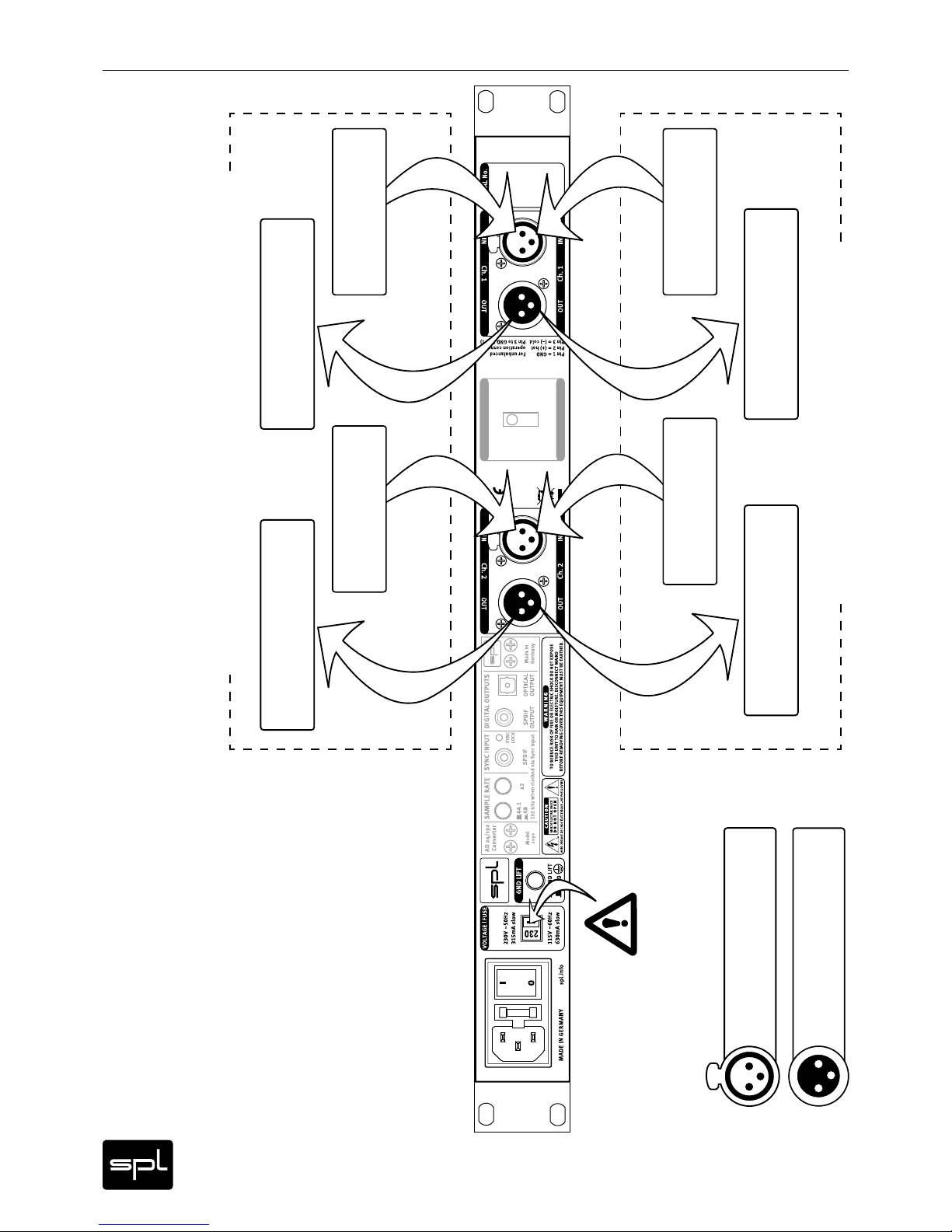
Rear Panel | Wiring Diagram
Ch. 1 OUT = Ch. 2 IN
Ch. 1 OUT = Ch. 2 IN
ON
OFF
Make sure that the voltage switch setting
reflects the correct local power line voltage.
Console, Patchbay,
DAW/Interface
Console, Patchbay,
DAW/Interface
Console, Patchbay,
DAW/Interface
Pin wiring XLR input sockets:
1=GND, 2=hot (+), 3=cold (-)
Pin wiring XLR output sockets:
1=GND, 2=hot (+), 3=cold (-)
PUSH
2
1
3
21
3
Console, Patchbay,
DAW/Interface
Microphone Microphone
Line SignalLine Signal
Wiring Diagram for Microphone Preamplifier Modules
Wiring Diagram for Processing Modules
Page 13
13
Analog Elemental Series
Rear Panel | Versions
OUT INCh. 1
IN OUTCh. 1
OUT INCh. 2
IN OUTCh. 2
MADE IN GERMANY spl.info
AVIS: RISQUE DE CHOC ÉLECTRIQUE – NE PAS OUVRIR
RISK OF ELECTRIC SHOCK
DO NOT OPEN
CAUTION
Pin 1 = GND
Pin 2 = (+) hot
Pin 3 = (–) cold
For unbalanced
operation connect
Pin 3 to GND (Pin 1)
SERIAL No.
VOLTAGE | FUSE
GND LIFT
GND LIFT
GND
TO REDUCE RISK OF FIRE OR ELECTRIC SHOCK DO NOT EXPOSE
THIS UNIT TO RAIN OR MOISTURE. DISCONNECT MAINS
BEFORE REMOVING COVER.THIS EQUIPMENT MUST BE EARTHED.
WARNING
0
I
230V ~50Hz
800mA slow
115V ~60Hz
1.6 A slow
OUT INCh. 1
IN OUTCh. 1
OUT INCh. 2
IN OUTCh. 2
MADE IN GERMANY spl.info
AVIS: RISQUE DE CHOC ÉLECTRIQUE – NE PAS OUVRIR
RISK OF ELECTRIC SHOCK
DO NOT OPEN
CAUTION
Pin 1 = GND
Pin 2 = (+) hot
Pin 3 = (–) cold
For unbalanced
operation connect
Pin 3 to GND (Pin 1)
SERIAL No.
VOLTAGE | FUSE
GND LIFT
GND LIFT
GND
TO REDUCE RISK OF FIRE OR ELECTRIC SHOCK DO NOT EXPOSE
THIS UNIT TO RAIN OR MOISTURE. DISCONNECT MAINS
BEFORE REMOVING COVER.THIS EQUIPMENT MUST BE EARTHED.
WARNING
0
I
Ch. 1 OUT = Ch. 2 IN
Ch. 1 OUT = Ch. 2 IN
ON
OFF
230V ~50Hz
800mA slow
115V ~60Hz
1.6 A slow
OUT INCh. 1
IN OUTCh. 1
OUT INCh. 2
IN OUTCh. 2
MADE IN GERMANY spl.info
AVIS: RISQUE DE CHOC ÉLECTRIQUE – NE PAS OUVRIR
RISK OF ELECTRIC SHOCK
DO NOT OPEN
CAUTION
Pin 1 = GND
Pin 2 = (+) hot
Pin 3 = (–) cold
For unbalanced
operation connect
Pin 3 to GND (Pin 1)
SERIAL No.
VOLTAGE | FUSE
GND LIFT
GND LIFT
GND
TO REDUCE RISK OF FIRE OR ELECTRIC SHOCK DO NOT EXPOSE
THIS UNIT TO RAIN OR MOISTURE. DISCONNECT MAINS
BEFORE REMOVING COVER.THIS EQUIPMENT MUST BE EARTHED.
WARNING
OPTICAL
SPDIF
SPDIF
AD 24/192
Converter
DIGITAL OUTPUTSSYNC INPUT
SAMPLE RATE
OUTPUT OUTPUT
SYNC
LOCK
Model
1090
Made in
Germany
x2
192 kHz when clocked via Syn c Input
48
44.1
0
I
Ch. 1 OUT = Ch. 2 IN
Ch. 1 OUT = Ch. 2 IN
ON
OFF
230V ~50Hz
800mA slow
115V ~60Hz
1.6 A slow
Depending on their configuration and additional features, the Analog Elemental Series
modules can have three different rear panels. The additional elements are the optional AD
converter (digital output) and the channel strip switch, which internally forwards the output
signal of the f irst module to the input of the second module, ruling out the need for external
cabling.
Rear Panel 1
Without converter or channel strip switch (configuration example: two preamp module).
Rear Panel 2
Without converter, with channel strip switch (configuration example: channel strip consisting
of preamp and processing module).
Rear Panel 3
With converter and channel strip switch (configuration example: channel strip consisting of
preamp and processing module, including digital output).
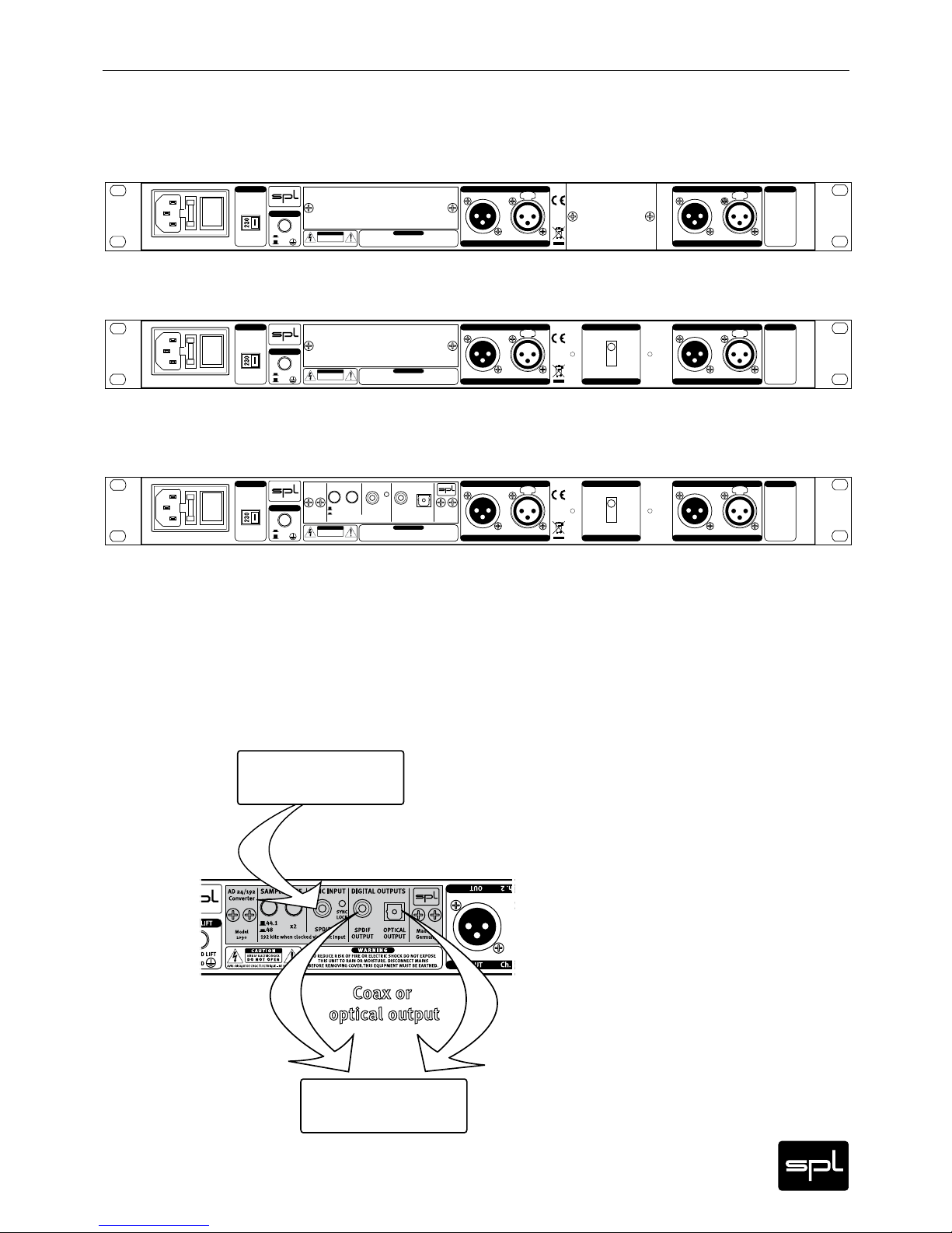
Optional Converter: Wiring Diagram
The optional AD conver ter provides an additional digital output. The diagram shows how to
connect it to an interface. For more detailed information refer to the converter module user‘s
manual.
DAW/Interface
(Output)
DAW/Interface
(Input)
Page 14

14
Analog Elemental Series
Rear Panel | Connections and Switches
Signal Connections
Turn off the unit before connecting or disconnecting any cable or equipment to it. Otherwise
you risk the possibility of damaging your ears or equipment.
Input and Output Electronics
The input and output electronics are based upon bridge circuits that keep the signal flow
constant, regardless of malfunctioning equipment and power outages (power fail safety
by relay hard bypasses). The bridge and insert circuits rely on high-quality relays. Contact
surfaces are gold-plated to provide better conductivity and encapsulated to avoid external
influences due to climate or atmospheric conditions.
XLR sockets
All signal connections are made via balanced XLR connectors. Inputs are always female and
accept male connectors; outputs are always male. All in all, a very comprehensible principle.
Balanced connections
It is impossible to exclude interferences when a single audio signal is transmitted. Shielding is
effective against electric, but not against electromagnetic influences. Motors, transformers,
and alternating current can always induce interferences. But even if the transmission would
succeed, dif ferences in ground potentials between driver and receiver would produce disturbances.
In balanced connections a reference signal with reversed polarity is transmitted additionally
to the audio signal through a second wire. The ground signal is routed separately through
a third wire. Input and output stages are drivers and receivers, and the receiving stage can
suppress interferences by subtracting the difference between audio and reference signal.
Unbalanced connections
Unbalanced connections from and to RCA or 1/4“ TS sockets can be made without adaptors to
the balanced XLR sockets. The correct wiring is important. The diagram shows the pin configuration of the XLR sockets and how to correctly connect them for unbalanced connections:
Connections to RCA sockets are always unbalanced, a wiring to jack connectors can be both
balanced (1/4“ TRS/stereo jack) or unbalanced (1/4“ TS/mono jack). We recommend to use
individually configured cables from XLR to RC A or jack sockets instead of adaptors. You can
get cables in any needed configuration from audio dealers. With the diagram above, the
dealer can ensure to provide the appropriate cable for your application.
Input
Output
balanced
unbalanced
balanced
unbalanced
1=GND
2= hot (+)
3= cold (-)
1
2
3
1
2
3
1
2
3
1
2
3
Page 15
15
Analog Elemental Series
Rear Panel | Connections and Switches
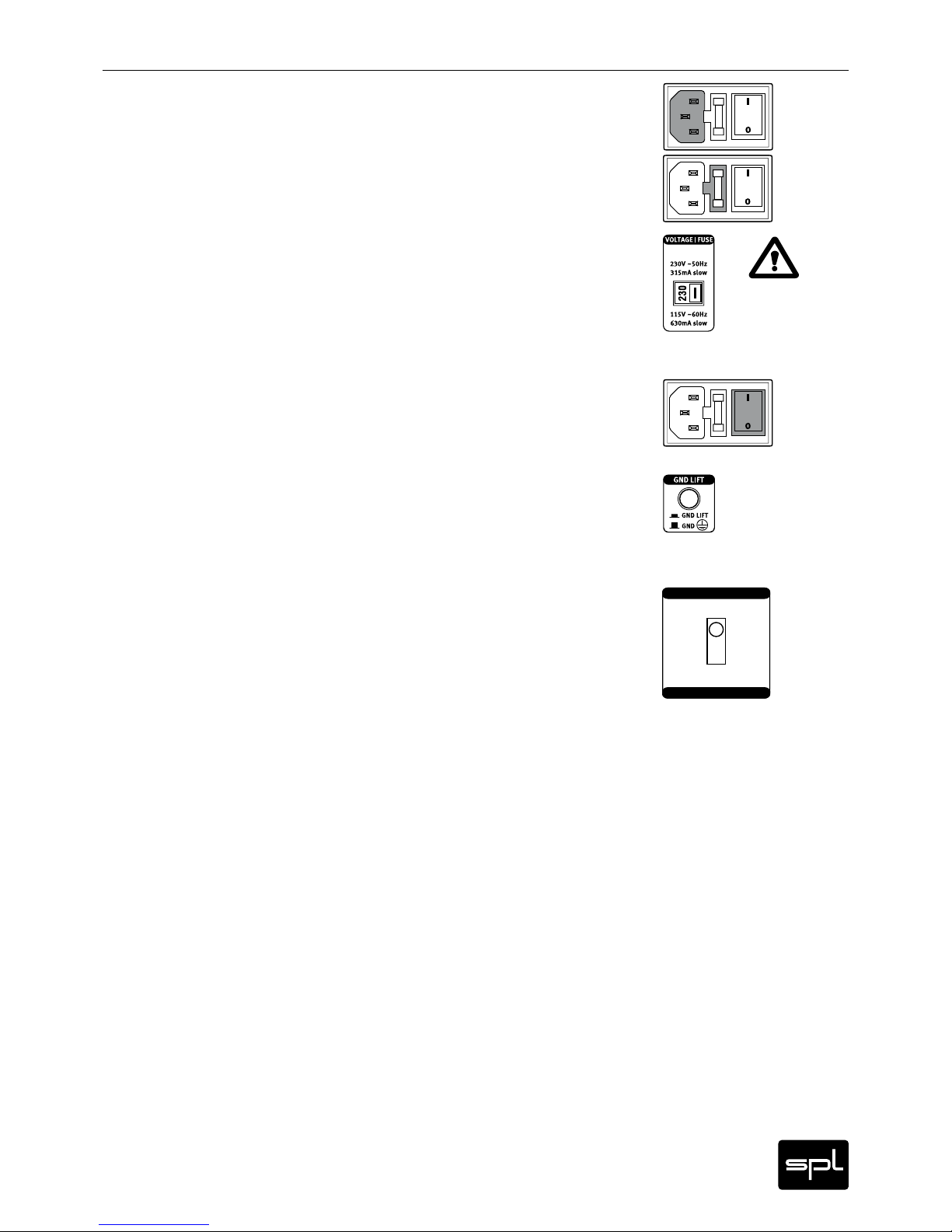
Power connection and fuse
Connect the power cord to the rear MAINS INPUT socket. Transformer, power cord and case
connection conform to VDE, UL and CSA requirements.
The fuse is accessible from outside and placed right behind the flap right from the socket.
Fuse ratings are 315 mA slow blow (
230
volts) or 630 mA slow blow (
115
volts).
Voltage Selector
The rear pan el VOLTAGE selector sets the lo cal line voltage (115 V position: 110 -120 volts/6o Hz,
230 V position: 220-240 volts/50 Hz). The diagram shows the correct switch position for 230 V
power supply.
BEFORE you connect electrical power make sure that the VOLTAGE selector setting reflects
the correct local power line voltage.
Power switch
Use the POWER switch on the rear panel to turn the unit on or off. The VU-meters on the front
panel will light on as soon as you turn the unit on, regardless of the position of the ACTIVE
push button. Thus, they fulfill a second function as power indicators.
GND Lift
The rear panel GND LIFT switch eliminates hum by separating the internal ground from the
unit’s housing ground. Hum can, for example, result when this unit’s housing has a common
ground connection with other devices that might have a diff erent ground potential . The switch
is usually deactivated to retain the shielding of the housing.
Channel Strip Switch (Ch. 1 OUT = Ch.2 IN)
The channel strip switch connects two modules internally with each other, as long as the
signal flow allows for it. For instance, with an Analog Elemental unit consisting of a preamp
and a processing module (Channel Strip configuration). When the switch is set to „ON“, the
output signal of the preamp feeds the input of the processing module directly. This simplifies the signal f low and makes it unnecessary to connect the output and input of the modules
externally via cables.
Ch. 1 OUT = Ch. 2 IN
Ch. 1 OUT = Ch. 2 IN
ON
OFF
Page 16
16
Analog Elemental Series
The Modules
Premium Mic Pre | Introduction
Premium Mic Pre | Control Elements
Each of the Analog Elemental Series units combines two of the following modules. For more
information on the design of the devices, refer to the Introduction on page 8. Here you will
find a detailed description of the single modules.
When recording acoustic instruments or vocals, using a microphone is inevi-
table. The actual output level of a microphone is very low and therefore has to
be boosted to studio or line level (0 dB) with a preamplif ier. Sometimes signals
have to be boosted by a factor of 2000 or more. As a consequence, the resulting
sound quality provided by the preamp is of paramount impor tance, so a good
microphone preamp that does not overdrive is the definitive requirement in order to
record acoustic instruments or vocals with sufficient dynamics and untainted sound.
The section “technology“ from page 19 explains how the Premium Mic Pre complies with
these requirements on the highest level and how it delivers premium results even in difficult
and critical set-ups.
Even the less technically interested users get an impression of the great efforts it takes in
development, circuitry design, selection of parts and assembly to create a product on the
Premium Mic Pre’s quality level. From there we deduce a superior price/performance ratio
– emphasizing on the performance which lends the Premium Mic Pre a world-class sound
quality.
Features
• The Premium Mic Pre offers preamplification values of up to +72 dB with lowest noise
operation and a high common mode rejection.
• Input stage and output are equipped with Lundahl transformers (High Performance
Series).
• A VU meter with two modes for average levels (VU) and peak levels (PPM) displays the
output levels.
• A very stable phantom power supply (48 V) is provided to power condenser microphones.
• The polarity of the microphone can be switched with the phase reverse switch.
• A high-pass filter protects against low frequency interferences.
• The signal LED indicates that an input signal is present
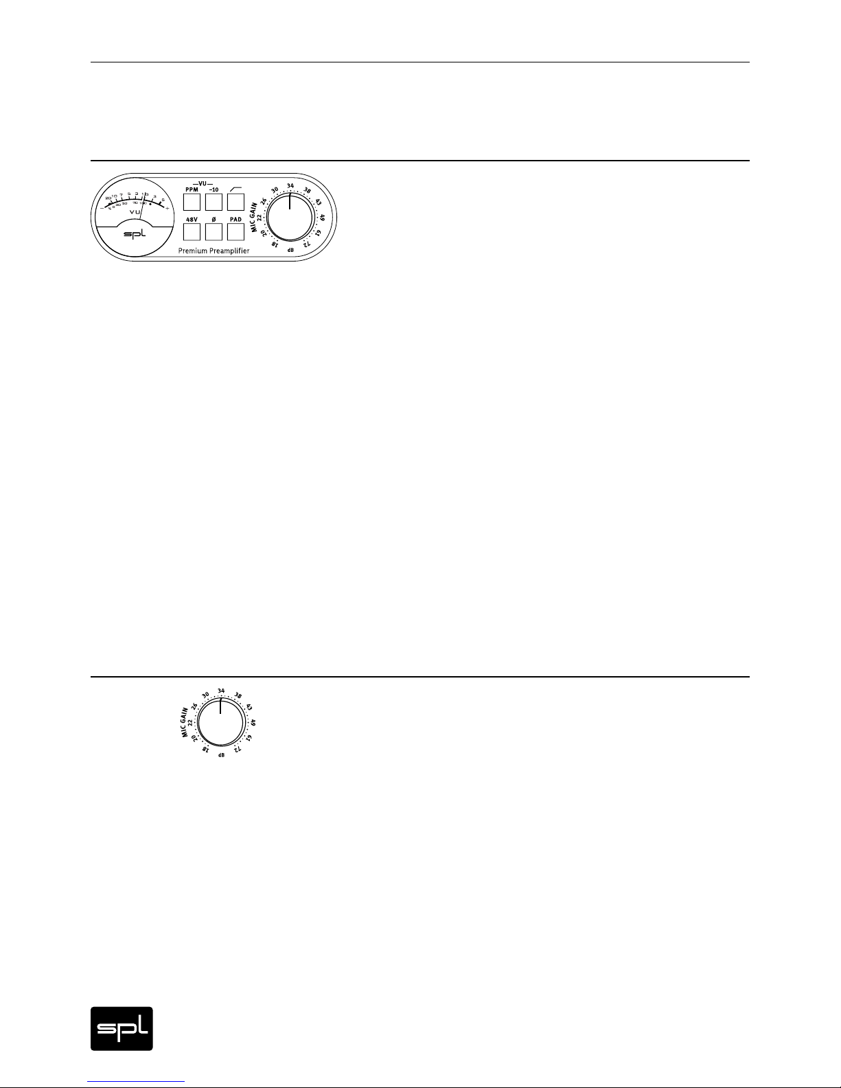
Mic Gain
With the Mic Gain control you can regulate the preamplification of the microphone signal.
It ranges from +18 dB to +72 dB. The input stage can handle input levels of up to 10 dB. The
value set with the Mic Gain control defines the output level.
When you set the Mic Gain you have to consider the type of microphone that you are using
(dynamic or condenser microphone) as well as its sensitivity. The sensitivity of a dynamic
microphone is at around 2 mV/Pa whereas the sensitivity of a condenser microphone can be
up to 20 mV/Pa. The result is a difference in output of 20 dB.
You should also consider the sound pressure level of the sound source, the distance of the
microphone to it and the acoustics of the room when you set the preamplification.
Page 17

17
Analog Elemental Series
Premium Mic Pre | Control Elements
About Leveling
Initially you should always deactivate the -10 dB button to have correc t values displayed by the
VU meter (see “-10 dB” below). Now turn up the Mic Gain control until the VU meter displays
maximum levels between 0 dB and +3 dB. At this level you don’t risk any overdrive when you
experience sudden and unexpected peaks in the level of the source. Always remember that
the VU meter only shows average values and that a peak level can be much higher (up to
+10 dB). If necessary, turn on the PPM mode to see the actual peak levels.
Usually levels of around 0 dB and +3 dB are safe. If, however, you experience very high peaks
already at minimum Mic Gain values (i.e. drums, brass instruments), you can activate the
PAD function (see “PAD” on page 18). The input level is now reduced so that you can regulate
Mic Gain again in a useful range.
If you know in advance that the level will be very consistent you can always turn up Mic Gain.
In this case you can activate the -10dB button to have more headroom in the display.
VU Meter
The VU meter displays the output level of the preamp. The gauge indicates levels from -20 dB
to +5 dB. If necessary you can lower the sensitivity by 10 dB so that the gauge goes up to
+15 dB output level (see “-10dB” below and “About Leveling” above).
The VU meter is custom made to meet SPL specifications and assures a balanced optical
perception thanks to it’s optimized ballistics.
An especially interesting feature is the option to switch between two display modes: VU mode
and PPM mode. The VU mode (VU=Volume Unit) displays average levels, thus provides information on the overall loudness. The PPM mode (PPM=Peak Program Meter) displays the peak
levels.
The integration time of the display complies with the BBC requirements. In VU mode the rise
time up to 0 dB is approx. 300 ms. In PPM mode the rise time up to 0 dB is about 2 ms and the
release time down to -20 dB is at a “slow” 1,5 seconds. This calibration ensures to display even
short peaks up to about +6 dB since the needle does not have to travel the entire distance of
the gauge every time.
PPM
The PPM button allows to switch the VU metering characteristics from VU display mode
(button is deactivated and not illuminated) to PPM display mode (button is active and illuminated). A/D converter display also make use of the PPM mode. Monitoring peak levels is most
important to avoid overloading the converter and to prevent audible distortion. Peak levels
are always above the average levels. It may make sense in most cases to also press the -10 dB
button to prevent the needle from getting stuck on the right side of the gauge.
-10
With this button you can change the sensitivity of the VU display. If you press the -10 dB button
(button is illuminated), the sensitivity of the display is lowered by 10 dB. With the needle for
example at 0dB, a value of +10 dB is displayed. Now you can read values of up to +15 dB.
You always have to add these 10 dB to the displayed values, for example if you compare these
values with those of an A/D converter. Remember that A/D converters show peak levels, not
average levels. For comparison press the PPM button to activate the PPM mode. >
Page 18

18
Analog Elemental Series
Premium Mic Pre | Bedienelemente
48 V Phantom Power Supply
The Premium Mic Pre provides 48 volt phantom power for microphones requiring external
current (generally condenser microphones). Such microphones are dependent upon a clean,
consistent and noise-free power supply for optimal operation and audio quality. The Premium
Mic Pre continuously delivers precisely 48 V and a maximum current of 14 mA, which will
power all microphones.
IMPORTANT: All microphones with balanced, ground-free outputs can be used with the
phantom power activated. Unbalanced microphones may only be used with phantom power
deactivated.
Phantom power should only be activated when using microphones that require it. Please be
sure to deactivate phantom power with all other microphones (including tube microphones
which are supplied from their own power supply, thus need no extra phantom power supply).
ALWAYS FOLLOW THESE RULES WHEN WORKING WITH PHANTOM POWER – THE INPUT
STAGES OF THE PREMIUM MIC PRE CAN BE DAMAGED IF YOU DO NOT ACT ACCORDINGLY:
1. First connect the microphone to the Premium Mic Pre.
2. Then activate phantom power – you can star t working now.
3. When you have finished recording, turn the phantom power off f irst.
4. DO NOT disconnect the microphone from the Premium Mic Pre UNTIL phantom power has
been switched off for a minute and all residual current is discharged.
Pad
The Pad function allows you to attenuate the input signal by 20 dB so that you can process
even very high levels, i.e. from drums or brass instruments.
If the VU meter shows levels above +3 dB even while Mic Gain is set very low (and the -10 dB
button deactivated), the time has come to press the Pad button. It illuminates when it is activated.
Phase Reverse
With the phase reverse button you invert the polarity of the microphone signal. When not
pressed ( button is not illuminated) the polarity is in phase. After pushing the button (button
is illuminated) the polarity is inverted.
The phase reverse feature comes in very handy if you have to switch the polarity of the XLR
input according to the polarity of the microphone or the microphone cable. The pin wiring of
the XLR sockets are as follows: Pin 1 = ground, Pin 2 = hot (+), Pin 3 = cold (-).
Sometimes it is useful to switch the polarity of a microphone, for example in the case of M/S
miking. A second classic application is the miking of a snare drum with two microphones that
are placed above and below the snare: Since both drum heads move in the same direction
when the drum is played, the microphones are out of phase. Switch the polarity of the bottom
mic and you avoid any cancellations when you join both signals in the mix.
High-Pass Filter
The high-pass f ilter, also known as rumble filter, helps to eliminate any interferences
within the lowest frequencies. The f irst order filter operates smoothly with 6 dB per
octave, starting from 75 Hz with -3 dB. This characteristic usually helps in most cases
and has the least sonic disadvantages. If you need to filter on a more extreme scale, even
second order filters (12 dB/octave) are overstrained frequently and sonic disadvantages
become more and more apparent. In those cases a variable filter is the means of choice.
Page 19

19
Analog Elemental Series
Premium Mic Pre | Technology
Triple Stage Preamp
The preamplifier circuitry of the Premium Mic Pre is composed of three stages: a transformer, a discrete differential amplifier stage and an instrument preamplifier all contribute (in
different shares) to the main amplification. The three stage setup firstly ensures a load distribution that minimizes the risk of overloads. Secondly, each stage can be optimally configured
through select components and sophisticated circuits – a decisive advantage over single IC
circuitries where the main amplif ication is achieved by just one stage.
In addition, the potentiometer (as the control element of the differential amplifier stage) only
has to cover a range of approximately 68 dB while the maximum amplification is at around
80 dB. In practice this means that even very high amplification values are still outside of the
extreme control range positions – which are critical for any potentiometer.
Stage 1 – The Input Transformer
Inherent part of the Premium Mic Pre design are the input and output transformers of the High
Performance Series by Lundahl. These transformers are lavishly handcrafted. They replace
common input and output balancing stages. These classic components of fer a very high
sound quality and common mode rejection but they are also very reliable and provide connections and signals of superior quality.
Lundahl transformers have a very high reputation in terms of manufacturing quality and the
resulting longevity as we have seen proven impressively throughout many years of experience.
In any microphone preamplif ier the input transformer is of special relevance as it is an integral par t of the preamp circuitry: it contributes to the main amplification through a passive
and permanent boost of, in this case, 6 dB. The advantage of passive amplification over
active amplification is that it does not add any noise. A second advantage of integrating this
passive amplification is a signal processing that is, as a matter of principle, lower in overdrive
and noise throughout all following stages simply because the rest of the electronic circuit is
charged with 6 dB less at any setting of the amplification.
In addition, transformers ensure a galvanic isolation, preventing any disturbing or damaging
voltages from being carried in any of the two directions. Electromagnetic, high frequency or
digital interference has no more influence. Problems with humming e. g. in a live environment
that have been caused by differences in the potentials between the stage and the FOH do not
occur. Even a voltage that has accidentally or through technical failure been connected to a
ground line cannot be transmitted. So transformers can exclude even mishaps or problems in
an installation reaching the categories “improbable” till “unbelievable” ...
Further, the phantom powering of microphones does not require any condensers in the
preamp socket which has further sonic advantages.
From our personal listening impression we can recommend transformers in any case. The
advantages in operational safety can not be overestimated especially in critical or complex
installations for studio, live or broadcast applications.
Stage 2 – The Discrete Differential Amplifier
From the input transformer, the signal is routed to a discrete differential amplifier based upon
a quad parallel transistor circuitry. This parallel circuit of eight single transistors reduces
noise remarkably through distribution of load.
The discrete differential amplifier is the central amplif ying stage; here the amount of the
amplification is controlled by a current-carrying source. Control systems that are triggered
by current rather than voltage have the main advantage that possible negative effects of the
potentiometer will not affect the audio signal.
The discrete differential amplifier offers a maximum amplification of up to 68 dB. A servo
drive circuit actively eliminates DC offsets of the differential amplifier. Servo drive circuitry
minimizes DC offsets more effectively than conventional solutions that utilize capacitors by
setting the DC offset to almost 0 mV. In addition, the active servo drive solution has sonic
advantages over passive capacitors as it tends to produce less distortions.
Page 20

20
Analog Elemental Series
Premium Mic Pre | Technology
Premium Mic Pre | Technical Specifications
Stage 3 – The Instrumentation Amplifier
An instrumentation amplif ier is following the discrete dif ferential amplif ier to produce the
output signal’s voltage. Functionally a summing amplifier it eliminates possible disturbing
voltages and also contributes to the main amplification with an additional +6 dB.
Foil and Styroflex Capacitors
Only the best MKP and styroflex capacitors are used in the various circuits. They sound more
open and dynamic in contrast to the conventional ceramic capacitors.
Output Stages
The Premium Mic Pre is based upon a transformer output capable of driving very long cables
(up to a few hundred yards, depending on the capacity of the cables and the input stages on
the other end). The maximum output level is +22 dBu.
Audio
Frequency Range 10 Hz- 68 kHz (-3 dB)
CMR -87 dBu
(@ 1kHz with -30 dBu Input level and 30 dB Gain)
THD&N @ 1 kHz
Input Level Gain THD&N
-30 dBu 30 dB 0,007 1%
-60 dB u 60 dB 0,078%
S/N Ratio Gain A/N Ratio A-weighted
80 dB -48,3 dBu
60 dB -64 ,2 dBu
30 dB -89, 0 dBu
E.I.N. (Equivalent Input Noise): -128 ,3 dBu
Dynamic Range 111,0 dB
Input
XLR socket, transformer balanced
Impedance unbalanced ca. 2,0 kOhm
Impedanz balanced ca. 4,0 kOhm
Max. Input Level +10 dBu, +30 dBu with Pad activated
Output
XLR socket, transformer balanced
Impedance unbalanced ca. 60 Ohm
Impedance balanced ca. 120 Ohm
Max. Output Level +22 dBu
Control Elements
Mic Gain Range 18 dB – 72 dB
Pad Switch -20 dB
High-Pass Filter fg = 75 Hz (-3 dB)
Phantom Power Supply 48 V
0 dBu = 0,775 V. Sugbject to change without notice.
Page 21

21
Analog Elemental Series
Premium Mic Pre | Block Diagram
Page 22

22
Analog Elemental Series
Preference Mic Pre | Introduction
Preference Mic Pre | Control Elements
When recording acoustic instruments or vocals, using a microphone is inevitable. The
actual output level of a microphone is very low and therefore has to be boosted
to studio or line level (0 dB) with a preamplifier. Sometimes signals have to be
boosted by a factor of 2000 or more. As a consequence, the resulting sound
quality provided by the preamp is of paramount importance, so a good micro-
phone preamp that does not overdrive is the definitive requirement in order to
record acoustic instruments or vocals with sufficient dynamics and untainted sound.
The section “Technology” on page 24 explains how the Preference Mic Pre meets these
requirements.
Main Features
• The Preference Mic Pre offers preamplification values of up to +72 dB with lowest noise
operation and a high common mode rejection.
• A VU meter with two modes for average levels (VU) and peak levels (PPM) displays the
output levels.
• A very stable phantom power supply (48 V) is provided to power condenser microphones.
• The polarity of the microphone can be switched with the phase reverse switch.
• A high-pass filter protects against low frequency interferences.
Mic Gain
With the Mic Gain control you can regulate the preamplification of the microphone signal. It
ranges from +18 dB to +72 dB. The input stage can handle input levels of up to 18 dB. The value
set with the Mic Gain control defines the output level equally for both Output 1 and Output 2.
When you set the Mic Gain you have to consider the type of microphone that you are using
(dynamic or condenser microphone) as well as its sensitivity. The sensitivity of a dynamic
microphone is at around 2 mV/Pa whereas the sensitivity of a condenser microphone can be
up to 20 mV/Pa. The result is a difference in output of 20 dB.
You should also consider the sound pressure level of the sound source, the distance of the
microphone to it and the acoustics of the room when you set the preamplification.
About Leveling
Initially you should always ensure to have deactivated the -10 dB button so that the VU meter
displays correct values (see “-10 dB” onthe next page). Now turn up the Mic Gain control until
the VU meter displays maximum levels between 0 dB and +3 dB. At this level you don’t risk
any overdrive when you experience sudden and unexpected peaks in the level of the source.
Always remember that the VU meter only shows average values and that a peak level can be
much higher (up to +10 dB). If necessary, turn on the PPM mode to see the actual peak levels.
Usually levels of around 0 dB and +3 dB are safe. If, however, you experience very high peaks
already at minimum Mic Gain values (i.e. drums, brass instruments), you can activate the PAD
function (see “PAD” on page 24). The input level is now reduced so that you can regulate
Mic Gain again in a useful range.
If you know in advance that the level will be very consistent you can always turn up Mic Gain.
In this case you can activate the -10dB button to have more headroom in the display.
Page 23

23
Analog Elemental Series
Preference Mic Pre | Control Elements
VU Meter
The VU meter displays the output level of the preamp. The gauge indicates levels from -20 dB
to +5 dB. If necessary you can lower the sensitivity by 10 dB so that the gauge goes up to
+15 dB output level (see “-10 dB” below and “About Leveling” on the previous page).
The VU meter is custom made to meet SPL specifications and assures a balanced optical
perception thanks to it’s optimized ballistics.
An especially interesting feature is the option to switch between two display modes: VU mode
and PPM mode. The VU mode (VU=Volume Unit) displays average levels, thus provides information on the overall loudness. The PPM mode (PPM=Peak Program Meter) displays the peak
levels.
The integration time of the display complies with the BBC requirements. In VU mode the rise
time up to 0 dB is approx. 300 ms. In PPM mode the rise time up to 0 dB is about 2 ms and the
release time down to -20 dB is at a “slow” 1,5 seconds. This calibration ensures to display even
short peaks up to about +6 dB since the needle does not have to travel the entire distance of
the gauge every time.
PPM
The PPM button allows to switch the VU metering characteristics from VU display mode
(button is deactivated and not illuminated) to PPM display mode (button is active and illuminated). A/D converter display also make use of the PPM mode. Monitoring peak levels is most
important to avoid overloading the converter and to prevent audible distortion. Peak levels
are always above the average levels. It may make sense in most cases to also press the -10 dB
button to prevent the needle from getting stuck on the right side of the gauge.
-10 dB
With this button you can change the sensitivit y of the VU display. If you press the -10 dB button
(button is illuminated), the sensitivity of the display is lowered by 10 dB. With the needle for
example at 0dB, a value of +10 dB is displayed. Now you can read values of up to +15 dB.
You always have to add these 10 dB to the displayed values, for example if you compare these
values with those of an A/D converter. Remember that A/D converters show peak levels, not
average levels. For comparison press the PPM button to activate the PPM mode.
48 V Phantom Power Supply
The Preference Mic Pre provides 48 volt phantom power for microphones requiring external
current (generally condenser microphones). Such microphones are dependent upon a
clean, consistent and noise-free power supply for optimal operation and audio quality. The
Preference Mic Pre continuously delivers precisely 48 V and a maximum current of 14 mA,
which will power all microphones.
IMPORTANT: All microphones with balanced, ground-free outputs can be used with the
phantom power activated. Unbalanced microphones may only be used with phantom power
deactivated.
Phantom power should only be activated when using microphones that require it. Please be
sure to deactivate phantom power with all other microphones (including tube microphones
which are supplied from their own power supply, thus need no extra phantom power supply).
ALWAYS FOLLOW THESE RULES WHEN WORKING WITH PHANTOM POWER – THE INPUT
STAGES OF THE PREMIUM MIC PRE CAN BE DAMAGED IF YOU DO NOT ACT ACCORDINGLY:
1. First connect the microphone to the Preference Mic Pre.
2. Then activate phantom power – you can start working now.
3. When you have f inished recording, turn the phantom power off first.
4. DO NOT disconnect the microphone from the Preference Mic Pre UNTIL phantom power
has been switched off for a minute and all residual current is discharged.
Page 24

24
Analog Elemental Series
Preference Mic Pre | Control Elements
Pad
The Pad function allows you to attenuate the input signal by 20 dB so that you can process
even very high levels, i.e. from drums or brass instruments.
If the VU meter shows levels above +3 dB even while Mic Gain is set very low (and the -10 dB
button deactivated), the time has come to press the Pad button. It illuminates when it is activated.
Phase Reverse
With the phase reverse button you invert the polarity of the microphone signal. When not
pressed ( button is not illuminated) the polarity is in phase. After pushing the button (button
is illuminated) the polarity is inverted.
The phase reverse feature comes in very handy if you have to switch the polarity of the XLR
input according to the polarity of the microphone or the microphone cable. The pin wiring of
the XLR sockets are as follows: Pin 1 = ground, Pin 2 = hot (+), Pin 3 = cold (-).
Sometimes it is useful to switch the polarity of a microphone, for example in the case of M/S
miking. A second classic application is the miking of a snare drum with two microphones that
are placed above and below the snare: Since both drum heads move in the same direction
when the drum is played, the microphones are out of phase. Switch the polarity of the bottom
mic and you avoid any cancellations when you join both signals in the mix.
High-Pass Filter
The high-pass f ilter, also known as rumble filter, helps to eliminate any interferences
within the lowest frequencies. The f irst order filter operates smoothly with 6 dB per
octave, starting from 75 Hz with -3 dB. This characteristic usually helps in most cases
and has the least sonic disadvantages. If you need to filter on a more extreme scale, even
second order filters (12 dB/octave) are overstrained frequently and sonic disadvantages
become more and more apparent. In those cases a variable filter is the means of choice.
Page 25

25
Analog Elemental Series
Preference Mic Pre | Technology
SSM 2019
The Preference Mic Pre is suitable for all common dynamic and condenser microphones. It
works along the principles of an instrumentation amplifier which is a technology that is also
used in measurement and medical equipment due to its high common mode rejection of stray
pick-ups. It is based on the semiconductor SSM 2019 which sounds more balanced than available alternatives. Low noise and distortion values as well as a broad bandwidth and a fast
slew rate are its forte.
Servo Drive Design
The main focus during the development of the Preference Mic Pre was its acoustic transparency and its natural representation of the source signal. Reducing DC offsets in the audio
signal paths is a decisive part of this design job.
DC offsets are produced in relatively large amounts especially when amplifying a microphone
signal because the signal is amplified by extreme factors from the pico volt range to 0dB
nominal level. DC offsets impair the signal quality as they induce noise and distortion that
lead to a diffuse sound.
The Preference Mic Pre‘s servo drive design minimizes these problems much more effectively
than the common solution based on capacitors by setting the DC offset to almost 0 mV. In
addition to that, the active servo drive circuitry tends to produce less distor tions than passive
capacitors.
The servo drive design incorporates three operational amplif iers. The SSM 2019 is the first
op-amp. The second op-amp acts as a sensor to detect voltage differences. These dif ferences
are then compensated for in a third op-amp working as summing stage.
Of course an elaborate active servo drive circuitry is a more expensive solution than simply
using passive capacitors, but especially in a microphone preamplifier this effort pays off with
improved sound quality.
Foil And Styroflex Capacitors
Only the best MKP and styroflex capacitors are used in the various circuits. They sound more
open and dynamic in contrast to the conventional ceramic capacitors.
Output
The output stage is electronically balanced and capable of driving very long cables (up to a
few hundred yards, depending on the capacity of the cables and the input stages on the other
end). The maximum output level is +22 dBu.
Page 26

26
Analog Elemental Series
Audio
Frequency Range 10Hz to › 200 kHz
CMR -84 dBu
(@ 1 kHz with -30 dBu input level and 30 dB gain)
THD&N @ 1 kHz
Input Level Gain THD&N
-30 dBu 30 dB 0,0035%
-60 dB u 60 dB 0 ,047%
S/N Ratio Gain S/N Ratio A-weighted
72 dB -57,0 dBu
60 dB -69 ,0 dBu
30 dB -91 ,7 dBu
E.I.N. (Equivalent Input Noise) -129,0 dBu
Dynamic Range 114, 0 dB
Input
XLR socket, elektronically balanced
Impedance unbalanced ca. 1,6 kOhm
Impedance balanced ca. 3,2 kOhm
Max. Input Level +18 dBu, +38dBu with Pad activated
Output
XLR socket, elektronically balanced
Impedance unbalanced ca. 75 Ohm
Impedance balanced ca. 150 Ohm
Max. Output Level +22 dBu
Control Elements
Mic Gain Range 18 dB - 72 dB
Pad Switch -20 dB
High-Pass Switch fg = 75 Hz (-3 dB)
Phantom Power Supply 48 V
0 dBu = 0,775 V. Technical changes subject to change without notice.
Preference Mic Pre | Technical Specifications
Page 27

27
Analog Elemental Series
Preference Mic Pre | Block Diagram
Page 28

28
Analog Elemental Series
Back in the 1990ies, we developed an alternative way to process signals in order
to reduce sibilance based on phase cancellation. Unlike traditional compression
methods, this procedure is much more unobtrusive and simplifies control to one
single parameter. SPL‘s De-Esser quickly became a standard reference among
recording studios, broadcast stations and live sound engineers.
The most commonly used technology to remove sibilance is based on compression. In
addition to determining the threshold, the center frequency for processing must also be set.
The processing range can be up to two octaves in order to ef fectively address all possible
problems across the frequency spectrum. This results in one of the most critical disadvantages: the wide range of frequencies being processed leads to undesired effects such as
nasalization and lisper.
The SPL De-Esser works on the principle of phase cancellation to remove unwanted sounds.
And it also adds automatic sibilance detection, which allows processing to be limited only to
the range where sibilant sounds are present. The result is a neutral-sounding, unnoticeable
but highly ef fective processing that never requires fine tuning level and frequency settings.
This way de-essing has the least possible influence on the voice‘s timbre, avoiding side
effects like nasalization and lisper. Operation is limited to adjusting the processing intensity
with one single control. The SPL De-Esser is a safe and precise tool to solve sibilance problems, without having to compromise sound quality nor the hassle of permanently readjusting
settings.
The Dual-Band De-Esser
The Dual-Band De-Esser module expands on this concept by making use of two frequency
bands that can be used independently or jointly.
• Two de-esser stages increase processing effectiveness without introducing any audible
artifacts
• Focused processing with high and low bands
• Input signals are automatically adjusted so that processing is uniform, regardless of the
distance between source and microphone
• Male/Female modes that adapt processing in the lower band to male or female voices
HI-Band On, Low-Band On
Use the HI-BAND ON button to turn the HIGH-S-REDUCTION on or off. Use the LOW-BAND ON
button to turn the LOW-S-REDUCTION on or off. The buttons light up when engaged.
You can use the two processing stages separately or jointly. They are connected in series as
independent de-esser modules. The low-band de-esser is set first in the chain.
If both de-essers are engaged, there is interaction between them: a signal already processed
with the low-band de-esser is different from the raw material that the high-band de-esser
would otherwise process. That is the reason why the readings of the high band‘s SR LEDs
change when the low-band de-esser is engaged while the high-band processor is active.
Hard-Bypass: the Dual-Band De-Esser module features power outage protection based on
relay-controlled hard-bypass circuits to always guarantee signal flow from input to output. In
order to keep signal flow constant, the bypass is automatically activated whenever a voltage
drop or failure is detected.
Dual-Band De-Esser | Introduction
Dual-Band De-Esser | Control Elements
Page 29

29
Analog Elemental Series
Dual-Band De-Esser | Control Elements
Low S-Reduction
Use the LOW S-REDUCTION control to adjust the intensity of the sibilance reduction in
the lower frequency range. The center frequency for sibilance recognition is set at 7.6 kHz
in FEMALE mode and 6.4 kHz in MALE mode. For more information, please refer to section
“MALE/FEMALE“ below. The bandwidth of the low-band de-esser is 1.44 kHz.
Scale values for the f ilter are displayed in dB. The actual reduction values, i.e. af ter phase
cancellation, are displayed in the lower SR LEDs. Thus, when the control is set to 3 dB, actual
reduction might only be of around 1 dB.
The SR LEDs display sibilance reduction between -1 dB and -14 dB, first in 1 dB increments and
from 6 dB on in 2 dB increments.
In practice, for most applications, the best results are usually achieved when LOW
S-REDUCTION is set between 3 and 7.
High S-Reduction
Use the HIGH S-REDUCTION control to adjust the intensity of the sibilance reduction in the
upper frequency range.
The center frequency for sibilance recognition is set at 11.2 kHz with a 3 kHz bandwidth.
Scale values for the f ilter are displayed in dB. The actual reduction values, i.e. af ter phase
cancellation, are displayed in the upper SR LEDs. Thus, when the control is set to 3 dB, actual
reduction might only be of around 1 dB.
The SR LEDs display sibilance reduction between -1 dB and -14 dB, first in 1 dB increments and
from 6 dB on in 2 dB increments.
Please note that the MALE/FEMALE button has no effect on the high-band de-esser.
In practice, for most applications, the best results are usually achieved when HIGH
S-REDUCTION is set between 3 and 7.
Male/Female
The MALE/FEMALE button allows you to adjust the low-band de-esser to the type of voice
being processed. When engaged, the mode selected for the low-band de-esser is FEMALE,
otherwise the de-esser works in MALE mode. The mode selected affects the center frequency
for sibilance recognition: in FEMALE mode it is set at 7.6 kHz, while in MALE mode it is set at
6.4 k Hz.
These values have been determined by practical experience, so that the processor adapts
better to gender. Nevertheless, you cannot take for granted that these settings will suit every
single male and female voice. Consider the MALE/FEMALE function as an additional tool to
help you set the low-band de-esser more precisely according to your needs. Always trust your
ears to find the best settings.
Signal-LED (SIG.)
The SIG. LED indicates that an audio signal reaches the input with a level above -20 dB. This
LED helps the operator especially in complex setups to determine immediately whether the
Dual-Band De-Esser actually receives any signal.
Page 30

30
Analog Elemental Series
Audio
Frequenc y Range: 10 Hz-80 k Hz
CMR: ›60 dBu
@ 1 kHz, 0 dBu input level and unity gain
S/N Ratio: -106 dBu
A-weightedt
Dynamic Range: 128 dB
THD&N: 0,01%
@ 1 kHz, 0 dBu input level and unity gain
Input
XLR socket, electronically balanced, optionally transformer balanced
Impedance ca. 20 kOhm
Max. Input Level +22 dBu
Nominal Input Level +4 dBu
Output
XLR socket, electronically balanced, optionally transformer balanced
Output Impedance 75 Ohm/›600 Ohm with transformer
Max. Output Level +22 dBu
Control Elements
Signal- LED -20 dBu
Overload-LED +19 dBu (peak hold 1,5 seconds)
0 dBu = 0,775 V. Technical changes subject to change without notice.
Dual-Band De-Esser | Technical Specifications
Page 31

31
Analog Elemental Series
Dual-Band De-Esser | Block Diagram
Page 32

32
Analog Elemental Series
The DynaMax x probably is the most consequent interpretation of a “set & forget“
compressor concept. In keeping with the SPL design philosophy, it incorporates
many features not found on standard compressors, and a unique control system
makes is surprisingly easy to use.
The DynaMax x also offers a de-compression mode which may be used to counter
the effects of overcompression in previously processed source material.
Why is DynaMax x so different? Though auto attack and release functions are nothing new,
in the DynaMax x design, the time constants are automated in a very musical way. DynaMax x
optimizes all time constants in real time during processing so that the compression characteristics are continually matched to the source material.
The DynaMax x circuitry actually uses two of the excellent THAT 2181 VCAs in SPL’s Double
VCA-Drive mode configuration, which doubles the operating range while increasing transparency and reducing distortion. Another benef it of the DynaMaxx circuitry is that high
compression ratios do not affect high frequency detail – high amplitude, low-end bass can
be controlled without introducing pumping or other negative side-effects. Similarly, complex
stereo sources can be processed easily and very musically.
The DynaMax x has numerous applications in recording and mixing, as well as for live applications, and because of the level of intelligent processing within the unit, there are only two
controls to adjust per channel, making operation very intuitive.
Compression
The COMPRESSION control sets the compression intensity by var ying both Threshold and
Ratio simultaneously. The further the COMPRESSION control is turned clockwise (which
lowers the Threshold and increases the ratio), the more processing is extended to lower level
signals. The fully clockwise position is equivalent to a Ratio of 3:1.
The exact processing values are always depending on the source material. Loud signal
parts will always be processed with higher compression rates than quieter signal parts. The
DynaMaxx employs soft-knee compression characteristics, following the input signal‘s structures dynamically.
For gentle compression results, turn the COMPRESSION control clockwise until the Gain
Reduction LED ladder shows a peak level reduction of between 2 and 3 dB. Turning the
Compress control fur ther clockwise will lower the Threshold to include more low-level signals
into the compression process. At the same time, compression ratio is increased up to a
maximum of 3:1.
The following diagram shows the gain control curve in normal compression mode with three
different COMPRESSION settings. For better readability of the graph, the gain has been kept
at 0dB, so no compensation for the gain reduction is applied.
DynaMaxx | Introduction
DynaMaxx | Control Elements
Page 33

33
Analog Elemental Series
DynaMaxx | Control Elements
Make-Up Gain
The MA KE-UP GAIN con trol compensates fo r any level decrease w hen applying COMPRE SSION.
The higher the processing intensity the lower the overall output level, the more Gain will be
required to restore the same peak level.
Turn the MAKE-UP GAIN control clockwise until the peak level of the input is the same as the
peak level of the output. Use the GAIN REDUCTION LEDs for a precise adjustment. The control
has a range of 20dB.
If the DE-COMPRESSION mode is activated, the MAKE-UP GAIN control compensates for the
increase in peak level. Note that in this mode, turning the Gain control clockwise decreases
the output level.
Gain Reduction LEDs
The 10-digit LED ladder meter is capable of displaying gain changes to a resolution of 1dB over
the range -1 dB to -14 dB.
When applying COMPRESSION to the audio signal, the LED meter displays the amount of gain
reduction taking place. From here you can see how much gain to compensate for with the
MAKE-UP GAIN control.
When the DE-COMPRESSION mode is activated, the LED display shows the gain increase
imparted to high-level signals.
DE-COM. (De-Compression)
The De-Compression function inverts the operation of the compressor to produce new
dynamic headroom, which may be used to increase the dynamic range of a (previously overcompressed) signal.
The process may also be used to expand the dynamic range of other sources, such as drum
or synthesizer samples. Especially when creating loops, overcompressed samples can
result in lifeless sounds. With the DynaMax x you can simply de-compress the signals again.
Interesting effects can also be achieved by applying different settings to the channels of a
stereo source.
IMPORTANT: While MAKE-UP GAIN increases the output level in standard mode, this function
is also inverted in DE-COMPRESSION mode – turning the control clockwise reduces the output
level.
The following diagrams show different characteristic curves in DE-COMPRESSION mode. If
the Limiter is activated in DE-COMPRESSION mode, the intensity of processing is increased
remarkably. Especially peaks are expanded more intensively.
Page 34

34
Analog Elemental Series
DynaMaxx | Control Elements
FX Com. (Effect Compression)
The FX Com. mode allows to switch off the DynaMax x‘s perfectly automated dynamics
processing. In this mode a f ixed release time of 60ms is applied, but the Attack time is still
automated. This mode increases the perceived loudness in comparison with the normal
Compression mode, and audible compression artifacts can be generated for creative
purposes.
The gain of the audio signal is restored back to normal shortly af ter the 60ms Release time
has passed, creating deliberate breathing and pumping effects. The LED display provides a
visual impression of the increased processing speed. The higher the CompressION control
setting, the more intense those effects will become.
Lim. (Limiter)
In limiter mode the DynaMax x only processes the peak levels but leaves, in contrast to the
compressor mode, the gain structure of low-level signals unchanged. Limiter mode is useful
when working with ‘clipping-sensitive’ media or units and it improves the utilisation of digital
headroom as well as the bit resolution.
The COMPRESSION control sets the threshold in LIM. mode. The further the control is moved
clockwise, the lower the threshold, and all signals above the threshold will be submitted to
the limiting process as a fixed ratio of ∞:1.
The limiter is based upon a soft-knee limiting characteristic. In comparison with hard limiting
characteristics, soft limiting
is more unobtrusive and
sonically more natural.
When a peak level exceeds
the threshold, the level isn’t
suddenly reduced, as would
be the case with a hard
limiting characteristic, but
rather the soft limiting starts
its processing earlier. This
way, peak levels are limited
far more smoothly once the
threshold is reached. The
following measurements
illustrate various soft-knee
limiting cur ves:
On
With the ON button you can turn the device on or off. The ON button is illuminated when the
device is active.
Relay hard bypass circuits ensure signals to be directly switched from input to output in the
case power failures – this “Power Fail Safety“ feature guarantees signal flow in any situation.
If you operate a DynaMaxx module in LINK-Mode, the ON button of the master module
controls both modules. The LINK and ON buttons of the DynaMax x module that is currently in
LINK mode will thus be illuminated as well—although they have not been activated.
Page 35

35
Analog Elemental Series
DynaMaxx | Control Elements
DynaMaxx | Technology
Link
You can operate two DynaMax x modules at a time by activating the LINK mode. You can only
run two modules in the LINK mode at a time. Main applications may be in stereo processing.
When operated in LINK mode, both modules are operated by the master module’s control
voltage. This ensures a coherent stereo operation. In LINK mode, all controls of the master
module (left module) — including the ON and LINK switch — control the slave module. The
master also controls all switch illuminations on the slave. All controls of the slave module are
inactive in LINK mode.
NOTE: the GAIN REDUCTION LED Display of the slave module is switched off in Link mode.
If you press the LINK button of the slave module without establishing the LINK mode through
the master module, you will find that the LINK LED of the master module will not illuminate.
This tells you that you have pressed the wrong LINK button since the controls of the master
module control both devices in LINK mode.
Signal-LED (SIG.)
The SIG. LED indicates that an audio signal reaches the input with a level above -20 dB. This
LED helps the operator especially in complex setups to determine immediately whether the
DynaMaxx actually receives any signal. .
This section deals with the technical background of the DynaMaxx and explains why we felt
it necessary to do some things rather differently to the way other manufacturers do them. We
will also explain the benef its of the DynaMaxx design.
Generally, the func tion of an audio compressor is to compress the dynamic range of the source
signal by altering the gain of its signal path in response to the relative level of the signal as
compared to an arbitrary threshold level. In effect, this process can be thought of as providing
additional gain to low-level signals or reducing gain in the presence of high-level signals.
Why are conventional compressors unsatisfactory?
One of the main difficulties in setting up a compressor is choosing the time constants Attack,
Decay, Sustain, and Release (in short: ADSR). The most important time constants are Attack
and Release – in the context of gain control, Decay and Sustain are mostly f ixed and they
tend to play a minor role. The inappropriate choice of time constants is mainly responsible for
the familiar pumping or breathing effects. Threshold and Ratio are easier to set up, but when
high compression ratios are used, high frequencies tend to become over-compressed, which
makes the mater ial sound dull or lacking in presence. It is normal to set up compressors based
on the loudest peak in the program material, in which case the parameters are optimized
for this moment in time only. The rest of the time, the time constants are less than optimal.
Taking into consideration that each musical instrument has varying attack and release times,
depending not only on the character of the instrument, but also on the way it is played, you
can see that it is almost impossible to choose a set of fixed parameters that will be correct for
an entire piece of music. Setting up a conventional compressor perfectly for recording a vocal
part is nearly impossible. However, perfect gain control is extremely important with digital
systems to make the best possible use of the available digital headroom while preventing
clipping. Vocals can have an extremely wide dynamic range, so for the best results, it may
become necessary to re-adjust the compressor settings while recording.
The DynaMax x solves these problems by the use of intelligent automation. It optimizes At tack
and Release times on the f ly, which is why the control system is so simple. Both Threshold and
Ratio are combined within the Compress-control, and the advanced Double VCA techno logy
maintains signal clarity, even at high levels of compression.
Page 36

36
Analog Elemental Series
DynaMaxx | Technology
Full-Band versus Multi-Band
Some compressors try to solve the problem of high frequencies being modulated by low
frequency compression by moving to a split band system, so why don‘t we do that?
Multi-band compression seems like a good idea to overcome the pumping effects caused by
heavy bass compression also causing high frequency sounds to be pulled down in level. For
example, with a regular compressor, you may be compressing a bass-drum but the release
time is set a little too long with the result that the following hi-hat gets ducked in level. Multiband technology splits the original signal into two or more bands to be processed individually, and in this way, heavy gain reduction at the bass end doesn’t affect the level of the high
frequencies.
Sounds like a good idea, but the elaborate level of automation and the double VC A circuitry
allow to dispense with multi-band techniques – and that provides two main advantages:
1. Neutral Sound
Multi-band technology has a significant sonic short-coming: due to different levels of
processing within the various bands, each band’s output may be changed in phase response,
so that when the bands are recombined, the signal tends to have reduced dimensions and
sounds incoherent and colored.
2. Time Saving
DynaMaxx offers simplicity of control. With Multi-band systems you have to set all the time
constants plus Gain, Threshold, and Ratio for each band. With a fully manual Four-Bandcompressor, this would mean 20 parameters to set up per channel. DynaMaxx needs 2 – and
provides better sound results.
Attack Time Automation
First it’s necessary to see what happens when a compressor is used with a fixed attack time
setting. For example, the sound of an e-bass can either come in smoothly (especially with
fretless basses), or with a very fast transient attack when slapping. If the attack time is set to
minimum (very short), the compressor is able to catch the peak of the transient attack but any
following notes will suffer increased transient distortion because the control voltage within
the compressor rises further as successive notes are processed. This behavior is sometimes
described as ‘surfing’, and can be overcome by setting a lightly longer attack time, but now
some peak s get through because they are f aster than the compressor’s attack time. Including
a separate Peak-Limiter to catch those fast transients has disadvantages: if this is done using
two VCA stages, the signal undergoes more quality degradation than is desirable, but even
with designs that use the same VCA for both compression and limiting, you still end up with
more controls than necessary.
The DynaMax x doesn’t need a separate peak limiter, because it detects and controls very fast
transients automatically. Processing is so fast that all signals stay within the soft-knee curve
for a more natural sound.
The attack time can be reduced in the instant of a percussive hit or bass guitar slap to a
minimum of 50 microseconds. As soon as the peak is passed, the attack returns to a longer
time constant (up to 10ms of first Attack time circuitry), and in this way, both pumping and
distortion are avoided.
The ability of DynaMaxx to respond so quickly is clearly valuable when complex stereo mixes
are being treated. If, for example, a snare drum peak occurs, DynaMaxx rapidly changes to a
very short attack time so that the snare hit keeps its original transient characteristics rather
than sounding ‘softened’. Following signals are compressed using longer attack times immediately.
The DynaMax x uses 12dB/octave f iltering instead of the 6dB/octave filtering used in standard compressor side-chains so as to increase the precision and speed of transient detection
and processing. The signal-dependent adjustment of the attack time parameter is too fast
to be audible. If the DynaMax x is operated in its normal compression mode, breathing and
pumping effects are avoided.
Page 37

37
Analog Elemental Series
DynaMaxx | Technology
Release Time Automation
Again, it is benef icial to look at what happens when the Release time is too shor t: In this case
the compressor will restore normal gain conditions as soon as the peak has passed, and this
rapid increase in gain is what we call breathing. Breathing is especially annoying during a part
with sof t strings or low level layered sounds – whenever a peak comes along, the strings duck
down with it, only to pump up again when the peak is over. Sonically the sound image swims
and pumps while the subjectively perceived loudness remains at a low level.
The DynaMax x uses a special technique to overcome these problems. First it monitors the
average music level. If a loud transient sound occurs (bass drum, snare and so on) that also
has a big gain step, a ver y short Release time is set and the signal level is reduced to the calculated average music level, not to the threshold! If the compressor reduces the level to the
Threshold (which is what standard compressors do), you would again hear pumping effects,
because of the way low-level signals are lifted in gain.
The Release time is controlled depending on the difference between the actual peak and
calculated average signal levels. If a large difference is detected, DynaMaxx will set a faster
Release time, whereas if only a small level difference is detected, DynaMax x will release more
slowly.
Threshold And Ratio
Threshold and Ratio are both set by the COMPRESSION control; using a low setting for the
COMPRESSION control causes only the peak levels to be compressed because the threshold
is relatively high. For more compression, turning the control clockwise has the ef fect of
lowering the threshold to include more low-level signals in the processing.
As the threshold is lowered, the ratio is simultaneously increased, and the fully clockwise
position is equivalent to a ratio of around 3:1. However, the threshold and ratio values are
not static, but rather vary depending on the attack and level characteristics of the source
signal. Peak levels are automatically compressed with a higher ratio to maintain control over
maximum signal levels, but still using an unobtrusive sof t-knee compression characteristic.
Page 38

38
Analog Elemental Series
Audio
Frequency Response 10 Hz - 200 kHz
CMR ›70 dBu
(@ 1 kHz, 0 dBu input level, unity gain)
THD 0,06%
(0 dBu input level, unity gain)
Noise (A-weighted) -93 dBu
(Make Up Gain 0 dBu)
Dynamic Range 115 dB
Input
XLR connection, electronically balanced, optionally transformer balanced
Impedance ca. 20 kOhm
Max. Input Level +21 dBu
Output
XLR connections, electronically balanced, optionally transformer balanced
Impedance ca. 150 Ohm
Max. Output Level +22 dBu
0 dBu = 0,775 V. Specifications subject to change without notice.
DynaMaxx | Technical Specifications
Page 39

39
Analog Elemental Series
DynaMaxx | Block Diagramm
Page 40

40
Analog Elemental Series
The Transient Designer provides a revolutionary concept for level-independent
dynamic processing. In this it differs in principle from common compressors that
are based upon processing signals of a specific level. Working with the Transient
Designer is very simple: Attacks can be amplified or attenuated and sustain may
be prolonged or shortened. However, the possibilities for studio and live applica-
tion are seemingly endless.
Technical foundation is SPL‘s Differential Envelope Technology (DET) which allows level-independent dynamic processing by calculating differences in generated envelopes. These envelopes are always tracking the curve of the original signal to provide optimal results in every
moment of the music.
Thanks to the level-independent processing DET the setting of a threshold is needless. Other
common controls of dynamic processing, such as ratio or parameters for time-constants are
automated and optimized adaptively in a musical manner according to the characteristics of
the input signal.
So only two controls per channel are required to allow the user to completely reshape the
attack and sustain characteristics of a sound: attack can be amplified or attenuated by up to
15dB while sustain can be amplified or attenuated by up to 24 dB.
Thus, in a very obvious and simple way, the Transient Designer opens a whole new dimension
in dynamic processing with entirely new, stunning and vast possibilities for dynamic manipulation and processing that cannot even be duplicated with several daisy-chained, conventional compressors or other dynamics devices.
A new feature of the Transient Designer module is the output gain control that enables you
to compensate changes in the level of the processed signal. This ensures a simple and safe
adjustment of levels for any following device – especially A/D converters.
The Transient Designer uses the excellently specified THAT 2181-VCAs, which are particularly natural and transparent sounding and renowned for minimal distortion values. The 2181
processes highest amplitudes without damping of high frequencies or reducing bass.
The module is equipped with a relay hard bypass to ensure the switching audio signals
directly from input to outputs in the case of a power failure. Signal flow is always maintained.
On
With the ON button you can turn the device on or off. The ON button is illuminated when the
device is active.
Relay hard bypass circuits ensure signals to be directly switched from input to output in the
case power failures – this “Power Fail Safety“ feature guarantees signal flow in any situation.
If you operate a Transient Designer module in LINK-Mode, the ON button of the master module
(left) controls both modules. The LINK and ON buttons of the Transient Designer module that
is currently in LINK mode will thus be illuminated as well—although they have not been activated.
Attack
With the ATTACK control you can amplify or attenuate the attack of a signal by up to 15 dB.
The ATTACK control circuitry uses two envelope generators. One follows the shape of the
original curve and adapts perfectly to the dynamic gradient. The second envelope generator
produces an envelope with a slower attack. From the difference of both envelopes the VCA
control voltage is derived. Positive ATTACK values emphasize attack events, negative ATTACK
values smooth out the attack envelopes of sound events.
For an extensive description and explanation of the possible applications of the ATTACK
control please refer to “Applications” on pp. 42-43.
Transient Designer | Introduction
Transient Designer | Control Elements
Page 41

41
Analog Elemental Series
Transient Designer | Control Elements
Sustain
With the SUSTAIN control you can amplify or attenuate the sustain of a signal by up to 24 dB.
The SUSTAIN control circuitry also uses two envelope generators. One follows the shape of
the original curve and adapts perfectly to the dynamic gradient. The second envelope generator produces an envelope with a longer sustain. From the difference of both envelopes the
VCA control voltage is derived. The gradient of the control voltage matches the time flow of
the original signal.
Positive SUSTAIN values lengthen the sustain, negative SUSTAIN values shorten the sustain.
For an extensive description and explanation of the possible applications of the SUSTAIN
control please refer to “Applications” on pp. 42-43.
Output Gain
The OUTPUT GAIN control allows you to reduce the output signal by up to -22dB or boost it
by up to +6dB. This ensures that following devices receive an optimized level. The centered
12-o‘clock position of the control equals 0dB output gain.
IMPORTANT: In LINK mode, the master module does NOT transfer OUTPUT GAIN settings to
the slave-module. You ALWAYS have to set the output values of both modules manually.
Link Mode
You can operate two Transient Designer modules at a time by activating the LINK mode.
You can only run two modules in the LINK mode at a time. Main applications may be stereo
processings.
When operated in LINK mode, both modules are operated by the master module’s control
voltage. T his ensures a coherent s tereo operation . In LINK mode, all cont rols of the (l eft) mas ter
module—including t he ON and LINK s witch—control the sl ave module. Th e master als o controls
all switch illuminations on the slave. All controls of the slave module are inactive in LINK mode.
IMPORTANT: The only exception is the Output Gain control which always has to be set manually at each module.
If you press the LINK button of the slave module without establishing the LINK mode through
the master module, you will find that the LINK LED of the master module will not illuminate.
This tells you that you have pressed the wrong LINK button since the controls of the master
module control both devices in LINK mode.
Signal LED
The SIG. LED indicates that an audio signal reaches the input with a level above -20 dB. This
LED helps the operator especially in complex setups to determine immediately whether the
Transient Designer actually receives any signal.
Page 42

42
Analog Elemental Series
Transient Designer | Applications
The Transient Designer is ideally suited for use in professional recording, in project or home
studios and sound reinforcement applications.
For the first time you can manipulate and control the attack and sustain characteristics of a
signal regardless of level in the most intuitive and simple way. Usually equalizers are used
to separate instruments in a mix – the tonal aspect of the signal is considered, but not the
temporal aspect. The Transient Designer opens this further dimensions in signal processing.
By manipulating the at tack and sustain cur ves of a sound event, the mix can be made to sound
more transparent. Instruments can be mixed at lower levels while still maintaining their positions in the mix—but occupying less space.
During a remix or in general after miking you can arrange new positions of instruments.
Reduce ATTACK and increase SUSTAIN to move signals back into the mix that are too present.
Additionally, the FX parts of too dry signals are strengthened.
Applied to single instruments or loops the Transient Designer allows you to create entirely
new sounds and effects.
The following examples are given as suggestions and examples. The described procedures
with specific instruments can of course be transferred to others which are not mentioned
here.
Drums & Percussions
Processing drum and percussion sounds is probably the Transient Designer’s most typical
range of application, both from samples to live drum sets:
• Emphasize the attack of a kick drum or a loop to increase the power and presence in the
mix.
• Shorten the sustain period of a snare or a reverb-flag in a very musical way to obtain more
transparency in the mix.
• When recording a live drum set, shor ten the toms or overheads without physically damping
them. Usual efforts to damp and mike are reduced remarkably. Since muffling of any drum
also changes the dynamic response, the Transient Designer opens up a whole new soundscape.
• Miking live drums is considerably faster and easier because you can correct the apparent
‘distance‘ of the microphone by simply varying the ATTACK and SUSTAIN values.
• The Transient Designer is a perfect alternative to noise gates in live drum miking.
Adaptively reacting to the duration of the original signal, the sustain is shortened more
musically than with f ixed release times and a drumset is freed from any crosstalk quickly
and effectively.
• Create unusual dynamic ef fects including new and interesting pan effects. For example,
patch a mono loop through two channels of the Transient Designer and pan fully left and
right in the mix. Process the left channel with increased ATTACK and reduced SUSTAIN
while you adjust the right channel the opposite way and you get very special stereo loop
sounds. You have to try this to appreciate what it sounds like, but expect to hear a lot of
unusual stereo movement.
• Enjoy an amazingly simple integration of drum sounds into a mix. If the acoustic level of
a snare is expanded to approximately +4 dB by increasing the attack value, the ef fective
increase of peak levels in the overall mix is merely about 0.5 dB to 1 dB.
Page 43

43
Analog Elemental Series
Transient Designer | Applications
Guitars
Use the Transient Designer on guitars to soften the sound by lowering the ATTACK. Increase
ATTACK for in-the-face sounds, which is ver y useful and works particularly well for picking
guitars. Or blow life and juice into quietly played guitar parts.
Distorted guitars usually are very compressed, thus not very dynamic. Simply increase the
ATTACK to get a clearer sound with more precision and better intonation despite any distortion.
Heavy distortion also leads to very long sustain. The sound tends to become mushy; simply
reduce SUSTAIN to change that. If you, however, want to create soaring guitar solos that
would make even David Gilmour blush, just crank up the SUSTAIN control to the max and
there you go.
With miked acoustic guitars you can emphasize the room sound by turning up SUSTAIN. If
you want the guitars to sound more intimate and with less ambience, simply reduce SUSTAIN.
Bass: Staccato vs. Legato
Speaking of bass: Imagine a too sluggishly played bass track ... you may not have to re-record
it: Reduce the SUSTAIN until you can hear clear gaps bet ween the downbeats—the legato will
turn into a nice staccato, driving the rhythm-section forward.
Ambience
A common problem especially with tracks that are recorded and mixed in different studios:
Backings lack of ambience, and finding a reverb that “matches” takes time ... so simply
emphasize the original ambience by turning up the Transient Designer’s SUSTAIN control.
And the opposite problem, too much ambience, is similarly simply solved with the opposite
processing — just reduce SUSTAIN.
Keyboards & Sampler
Sounds in keyboards and samples are usually highly compressed and maintain only little of
natural dynamics. Increase the ATTACK values to re-gain a more natural response characteristic. The sounds occupy less space in the mix and appear more identif iable even at lower
volumes.
Post Production
When dealing with overdubs in movies you can easily add more punch and definition to effect
sounds from any sample library.
The same applies to outdoor recordings that suffer from poor microphone positioning—
simply optimize them afterwards.
Mastering
Like with any good thing, you also have to know where not to use it. For example, using a
Transient Designer in mastering is not recommended, as it is rarely a good idea to treat a
whole mix at once. Instead, treat individual elements within the mix.
Page 44

44
Analog Elemental Series
Audio
Frequency Response 10 Hz - 70 kHz
CMR -80 dBu
(at 1 kHz with 0 dBu input level/unity gain)
THD&N 0,019%
(0 dBu input level/unity gain)
S/N Ratio -89 dBu
(A-weighted)
Dynamic Range 111,0 dB
Input
XLR connector, electronically balanced, optionally transformer balanced
Impedance ca. 20 kOhm
Max. Input Level +21 dBu
Outputs
XLR connectors, electronically balanced, Output 1 optionally transformer balanced
Impedance ca. 150 Ohm
Max. Output Level +22 dBu
0 dBu = 0,775 V. Specifications subject to change without notice.
Transient Designer | Technical Specifications
Page 45

45
Analog Elemental Series
Transient Designer | Block Diagram
Page 46

46
Analog Elemental Series
The TwinTube module is the first ever combination of two essential tube effects into
a single processor, that is, saturation effects along with harmonics processing.
Both stages work separately from each other and are based on an individual tube
circuit, therefore each module employs two tubes. The effects can therefore not
only be applied both individually or separately, but also in common.
Saturation effects are generated through the tube being pushed to and beyond its
normal operating limits. In contrast to semiconductors, a tube thus pushed to such levels
does not clip from a certain level, approaching more gradually its level limits and thereby
producing its typical tonal result, which in audio signal processing can have such often profitable aural effects —on one hand (and depending on the amount applied), from subtle to
extensive harmonic distortion and on the other hand, a compaction of the sonic event, that is,
a limiting effect that exhibits a pleasant, rounded or soft sound.
Acoustically and also in its range of applications this can be compared very well with tape
saturation effects. Harmonic distortion and limiting are the generally known, “classic” tube
effects, which are today cornerstones of sound processing.
But other less known and potentially important ef fects are a tube’s ability for improving presence and spacial qualities through its processing of specific regions of the overtone series.
A special circuit comes into play for overtone/harmonic processing that involves a combined
coil/condenser system working in conjunction with the tube. The control reacts dynamically
to the audio signal and thereby processes both overtones as well as a signal’s phase structure.
The processing of the phase structure influences the moments of acoustic perception and
occurs in microsecond time divisions – it has to do nothing with the cancellations one associates with 180-degree signal shif ts. A decisive factor in resultant tonal quality is the alignment
of level relationships the overtone spectrum. Such overtone “enrichment” does not operate
on the generator principle of exciters (wherein distortion is added to the original signal). In
this case the TwinTube harmonics control effects a rather a more equalized overtone structure resulting in a sound which in effect appears much more in the foreground, but without
doing so through extreme level changes. Thus, for example, a voice appears immediate apart
from the overall mixture, “sitting” clearly outlined in the mix’s foreground.
HAR. ON/SAT. ON
Activating HAR ON engages the HARMONICS control. Likewise you engage SATURATION with
the switch SAT. ON. When turned on, these switches illuminate.
One of the both processing stages can be applied therefore respectively separately. Similarly
you can process the signal with both stages at the same time.
Warm-up phase: A warm-up phase for both tube stages begins after powering on the unit,
independent of the HAR. ON or SAT. ON switches. During the warm-up phase HAR ON and SAT.
ON flash alternately. The warm-up phase can last between 20 seconds and a minute. During
the warm-up phase the entire module remains in a bypass mode.
Hard-Bypass: For power fail safet y, the TwinTube module employs a relay hard bypass design.
It guarantees a direct switching from the inputs to the outputs in case of a power failure to
maintan the signal flow.
HARMONICS Control
With the HARMONICS Control you can adjust the overtone processing intensity. The available
level range of a chosen harmonics frequency (see “HARMONICS Switch” on the next page)
lies between 0 and 15 dB.
Overtones are marked also as “Harmonics”. The HARMONICS control result s in an enrichment
of the overtone range for a chosen fundamental tone (see “Introduction” above). The tonal
result is an intensification of the presence that produces a fresher, silky and more brilliant
aural image. Similarly, the signal’s spacial qualities gain in intensity.
TwinTube | Introduction
TwinTube | Control Elements
Page 47

47
Analog Elemental Series
HARMONICS Switch
With the HARMONICS switch you choose the frequency range of the fundamental tone area
that should be processed with the HARMONICS control. There are four available frequency
ranges with respec tive center frequencies of 9.8 kHz, 6.6 kHz, 2.8 kHz and 1.9 kHz. For reasons
of space, we have rounded f requency values for the values on the front panel. The bandwidths
of the filters are listed under “Specifications, Harmonics Filter” on page 50.
The frequency ranges are based up on our experiences and test series to of fer ideal processing
ranges for wide variety of instruments (and vocals of course). You may find further information under „Operation/Application Examples” below.
SATURATION Control
As the name implies, the SATURATION control determines the degree of the tube saturation.
At the most extreme level this SATURATION control output level may increase the overall
output level by approximately 6 dB.
The SATURATION control offers a wide range of effects intensity from most subtle to brutal
harmonic distortion. Aside from harmonic tube distor tion, the accompanying tube limiting
effect should also be considered. For further details on the saturation effect refer to the
“Introduction” on the previous page.
Signal LED
The SIG. LED indicates that an audio signal reaches the input with a level above -20 dB. This
LED helps the operator especially in complex setups to determine immediately whether the
TwinTube actually receives any signal.
Here we refer to only two significant examples, of course without suggesting completeness.
We would like to simplify starting with the TwinTube by sharing some thoughts and experiences in these applications areas. The ef fects and results described here can be applied to
many other instruments—nothing should keep you away from using the TwinTube without
restriction.
Vocals
Optimizing vocal tracks is a highlight among the processing applications of the TwinTube.
Often further EQing is not necessary anymore in order to lift a voice from a mix and get it up
front. A recommendation for female voices: HARMONICS switch to 6, HARMONICS control to
about 2 o’clock, SATURATION to about 12 o’clock.
With these settings the described effect should be clearly audible and from here individual
tracks can be optimized. With female voices we suggest tr ying HARMONICS switch settings 6
and 10 while switching between 2, 3, and 6 with male voices.
Acoustic Guitars
The success in treating e-guitars depends on previous recording and processing gear and
techniques—if tube amps and further ef fects were already applied, it is hard to foresee how
much the TwinTube can contribute when optimizing or designing a sound.
In contrast to e-guitars, there is a huge potential in processing acoustical guitar tracks.
Picking sounds can be intensified, in general tube saturation and limiting can improve loudness and condenses the sound. Presence is emphasized and the instrument cuts through a
mix much better without raising levels too much. A well chosen amount of harmonic distortion
always adds some roughness which may often be a nice touch in several playing styles.
Bedienelemente
TwinTube | Control Elements
TwinTube | Applications
Page 48

48
Analog Elemental Series
TwinTube | Measurements
Fast Fourier Transformation (FFT): 1 kHz/0 dBu input signal, SATURATION to maximum.
FFT: 1 kHz/0 dBu input signal , SATURATION to minimum.
Audio Precision 05/21/08 14:51 :51 A-A FFT SPECT RUM ANALYSIS
-140
+20
-130
-120
-110
-100
-90
-80
-70
-60
-50
-40
-30
-20
-10
+0
+10
d
B
u
2k 24k4k 6k 8k 10k 12k 14k 16k 18k 20k 22k
Hz
Audio Precision 05 /21/08 14 :53:01 A-A FFT SPECT RUM ANALYSIS
-140
+20
-130
-120
-110
-100
-90
-80
-70
-60
-50
-40
-30
-20
-10
+0
+10
d
B
u
2k 24k4k 6k 8k 10k 12k 14k 16k 18k 20k 22k
Hz
Page 49

49
Analog Elemental Series
TwinTube | Measurements
HARMONICS control at maximum.
THD vs. input level of the saturation stage at different control intensities (lower curve:
SATURATION control set to 0, upper curve: SATURATION set to 20).
Audio Precision 06/13/08 15:10:24RackPack TTP 2714
-20
+20
-15
-10
-5
+0
+5
+10
+15
d
B
u
10 80k20 50 100 200 500 1k 2k 5k 10k 20k
Hz
Audio Precision 06/13/08 15:07:45RackPack TTP 2714
-100
+10
-90
-80
-70
-60
-50
-40
-30
-20
-10
+0
d
B
u
-10 +20-5 +0 +5 + 10 +15
dBu
Page 50

50
Analog Elemental Series
AUDIO
Harmonics Stage
Frequenc y Range 10 Hz-80 k Hz
THD 0.1 %
@ 1 kHz, 0dBu input level, unity gain
Noise, A-weig hted -87 dBu
Dynamic Range 103 dB
Maximum Input Level +18 dBu
Harmonics Filter
Filter 1 Center Frequency: 9,8 kHz
Bandwid th: 9.6 k Hz
Maximum Gain: +15 dB
Filter 2 Center Frequency: 6.6 kHz
Bandwid th: 5 kH z
Maximum Gain: +15 dB
Filter 3 Center Frequency: 2.8 kHz
Bandwid th: 9 kH z
Maximum Gain: +15 dB
Filter 4 Center Frequency: 1.9 kHz
Bandwid th: 4 .7 kHz
Maximum Gain: +15 dB
Saturation Stage
Frequenc y Range 10 Hz-77 kHz
THD 0.02 % @ 1 kHz, 0dBu input level, unity gain
ca. 15 % @ 0dBu input level and maximum saturation
Noise, A-weig hted -96 dB u
Dynamic Range 114 dB
Maximum Input Level +21 dBu
AUDIO – CUMULATIVE (Harmonics and Saturation Stage)
Frequenc y Range 10 Hz-77 kHz
CMR -74 dB u
@ 1 kHz, 0dBu input level, unity gain
Noise, A-weig hted -87 dBu
Dynamic Range 105 dB
Input
XLR connector, electronically balanced, opt. transformer balanced
Max. Input Level +20 dBu
Impedance ca. 20 kOhm
Output
XLR connector, electronically balanced, optionally transformer balanced
Impedance ca. 150 Ohm
Maximum Output Level +21 dBu
Control Elements
Signal- LED -20 dB u
Overload-LED +18 dBu (peak hold 1,5 seconds)
0 dBu = 0,775 V. Specifications subject to change without notice.
TwinTube | Technical Specifications
Page 51

51
Analog Elemental Series
TwinTube | Block Diagram
Page 52

Analog Elemental Series
< English
Manual Analog Elemental Series
 Loading...