

Page 1
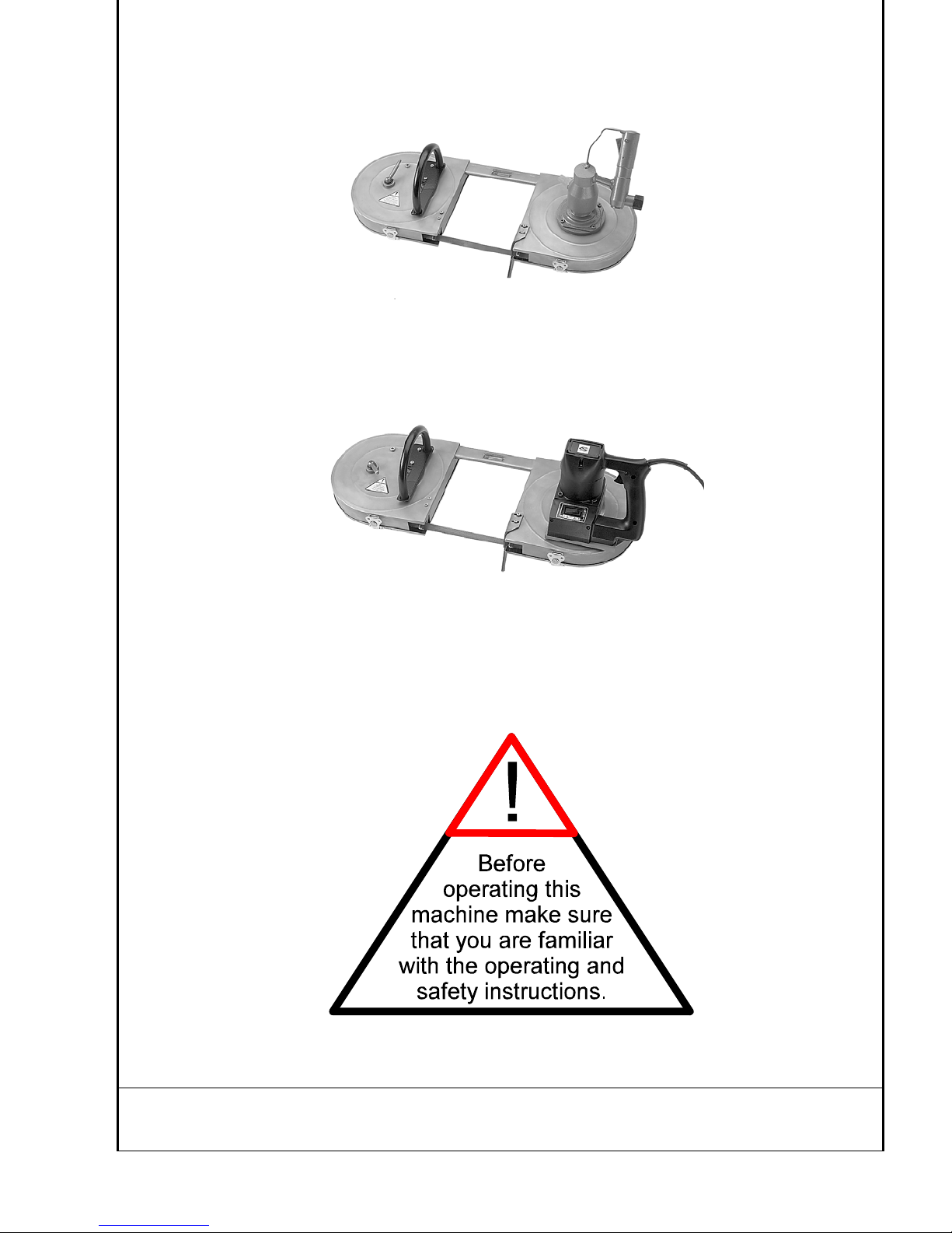
OPERATING MANUAL
5 6031 0010
Stainless Steel Pneumatic Band Saw
5 6047 0010
Stainless Steel Electric Band Saw
Manufactured by: SPITZNAS GmbH, POSTFACH 11 02 09, 42530 VELBERT, GERMANY
DISTRIBUTED CS UNITEC, INC. Toll Free: 800-700-5919 Web: www.csunitec.com
BY: 22 Harbor Avenue Tel: (203) 853-9522 Email: [email protected]
Norwalk, CT 06850 Fax: (203) 853-9921
Page 2
Contents
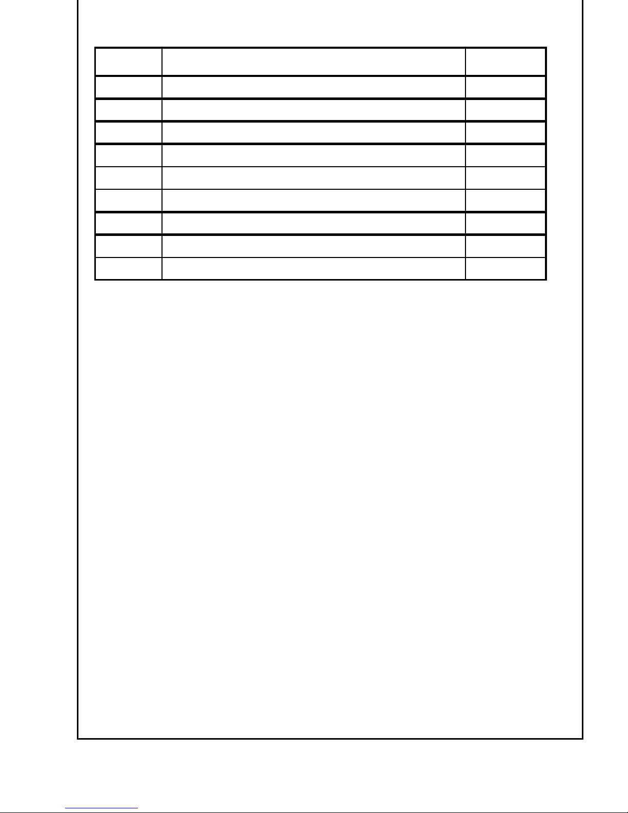
Chapter Description Page
1. Safety Instructions 3-4
2. Technical Data 5
3. Scope of Delivery / Accessories 6
4. Use / Cutting Hints 7
4.1 Trouble Shooting 8
4.2 Changing Saw Bands / Instructions 9-10
5. Operating Instructions and Maintenance 11-12
6. Disassembly and Reassembly 13-14
6.1 Spare Parts Lists and Sectional Drawings
Chapter 1: Safety Instructions
Make sure that you are familiar with the Safety Instructions before
operating the SPITZNAS Band Saw
Chapter 2: Technical Data of the Pneumatic Band Saw and Electric Band Saw
Chapter 3: Scope of Delivery and Accessories
Chapter 4: Use and Cutting Hints of the Band Saw
Chapter 5: Operating Instructions and Maintenance
Chapter 6: Disassembly and Assembly, Spare Parts lists ,
Sectional Drawings of the components.
2
Page 3
Safety Instructions
WARNING!
Risk of serious personal injury or death.
Read and follow instructions for proper use of this product.
Because of the harsh environment to which Band Saws are exposed, it is necessary
that you carefully follow all instructions accompanying your saw and its cutting
attachments. In particular, the following instructions are highlighted.
1. Plan ahead - lay the work out before starting. Always work in a steady manner.
Fatigue leads to carelessness and accidents. Never operate your tool while
you are under the influence of medication, alcohol, or other drugs.
2. Keep your work area clean and uncluttered and keep children and
unnecessary personnel away from your saw and work area.
3. Wear proper clothing. Clothing which is too tight or too loose is not
suitable; it can restrict your movements or be caught up by the saw band.
4. Protect your head and hair, eyes and ears, hands, legs and feet.
° Wear a hard hat, ear protectors and safety glasses
° Wear non-slip gloves to protect your hands
° Wear safety boots to protect feet and legs
5. Always disconnect power hose before attaching a saw band or working on the saw.
To disconnect Electric Motor unplug the cord from the pwoer outlet.
To disconnect Air Motor shut main air hose valve.
Open air valve to decompress hose before disconnecting it.
6. Do not operate the saw unless your body and weight are firmly balanced and secure.
Never use the saw while leaning from a ladder, scaffold or other structure. Grab the
saw with both hands during use. Keep hands and other body parts away from
cutting area. Exercise extreme care to prevent hands from contacting the saw band.
7. No obstructions. Be certain the object being cut does not contain electrical wires.
Use clamps or make sure the material to be cut is firmly held to prevent movement.
8. Slurry is very slick. Remove or control to prevent yourself, or others, slipping
while cutting.
9. Never carry the band saw with the motor running! Do not carry the saw with
the finger on or nearby the trigger switch or valve lever.
3
Page 4

10. Be alert for pieces which might fall down.
(Solid steel of 4“ dia. and 12“ length weighs about 40 lbs !)
11. Avoid sparks in hazardous environment - created by the saw band.
12. Use saw only with secured closed cover.
13. Do not operate saw with a damaged, modified, or broken cover.
ELECTRICAL SAFETY
1. Grounded tools must be plugged into an outlet properly installed and grounded in
accordance with all codes and ordinances. Never remove the grounding prong or
modify the plug in any way. Do not use any adaptor plugs. Check with a qualified
electrician if you are in doubt as to whether the outlet is properly grounded. If the
tools should electrically malfunction or breakdown, grounding provides a low
resistance path to carry electricity away from the user.
2. Avoid body contact with grounded surfaces such as pipes, radiators, ranges and
refrigerators. There is an increased risk of electric shock if your body is grounded.
3. Don’t expose power tools to rain or wet conditions. Water entering a power tool
will increase the risk of electric shock.
4. Do not abuse the cord. Never use the cord to carry the tools or pull the plug from
an outlet. Keep cord away from heat, oil, sharp edges or moving parts. Replace
damaged cords immediately. Damaged cords increase the risk of electric shock.
5. When operating a power tool outside, use an outdoor extension cord marked W-A
or W. These cords are rated for outdoor use and reduce the risk of electric shock.
4
Page 5
Technical Data
)
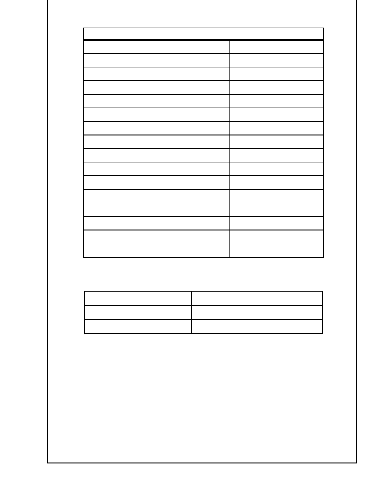
AIR BAND SAW NO. 5 6031 0010/20
Housing Stainless Steel
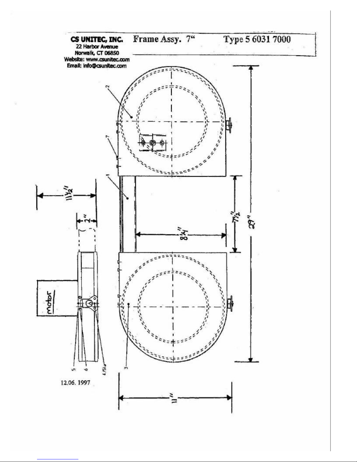
Cutting Capacity, dia. max. 7-1/4"
Cutting Capacity, rectangular max. 7-1/4" x 7-1/2"
Saw Band Size 66" x 5/8" x 0.025"
Overall Length 28 ¾ "
Height including Motor 11 ½ "
Width 11 ¼ "
Weight 28.7 LBS
Air Connection R 1/2" female
ID of Hose (minimum) ½ "
Standard Air Pressure 60 to 90 PSI
Air Consumption (at P =1.0 kW)
23 CFM
42 CFM
(at 60 PSI)
(at 90 PSI)
Motor Output 1.3 HP
Noise Level (Free Speed)
(measured in a distance of 1m)
83,8 dB(A)
87,3 dB(A
(at 60 PSI)
(at 90 PSI)
Electric Band Saw No. 5 6047 0010
Motor 120 VAC *, 50-60 HZ, 6 AMP
Free Surface Speed Variable 100-265 Ft/Min
* This motor is rated A.C. only. Do not use D.C. current otherwise serious
damage will occur.
5
Page 6
Scope of Delivery / Accessories
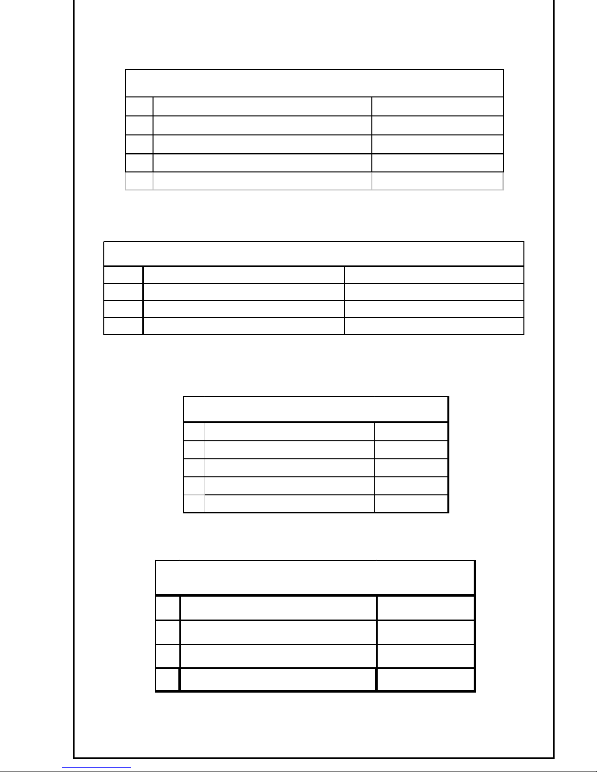
S tanda rd E quipm ent - E lectric B and Saw
Description Part No.
1. Band Saw Head 7-1/4" Dia. 5 6031 8000
2. Band Saw Motor 6 AMPS 5 6047 7724
3 Saw Blade 10-14 TPI 9 2506 0230
Standard Equipm ent - Air Band Saw
Description Part No.
1. Band Saw Head 7-1/4" dia. 5 6031 8000
2. Band Saw Motor 1.3 HP 5 6037 0020
3. Saw Blade 10-14 TPI 9 2506 0230
Additional Saw Blades
Description Part No.
1. Saw Blade 8 TPI 9 2506 0200
2. Saw Blade 14 TPI 9 2506 0220
3. Saw Blade 10-14 TPI 9 2506 0230
4. Saw Blade 8-12 TPI 9 2506 0240
Accessories
Description Part No.
1. Handle 5 6032 6010
2. Strap 9 5102 6000
3 Clamp on Vise 5 6031 9400
6
Page 7
Use and Cutting Hints
xPlan the cut.
x Know the material to be cut. If necessary, slow down surface speed
of saw band by reducing the air pressure.
x Verify material to be cut is firmly held to prevent movement.
x Hold the saw with the work stop contacting the work and saw band teeth
clear of the work.
x To start the air motor press valve lever with fingers.
To start the electric motor squeeze trigger switch.
Lower saw onto work. Allow weight of saw to control cutting pressure.
Additional pressure will slow down speed of the saw band.
Hold saw straight in the cut. Any twisting or cocking of the band results
in shorter saw band life.
If the saw band binds or jams in the cut shut off the motor and disconnect
the air supply. Free the saw band carefully.
CAUTION: Stay clear of end pieces that may fall down after being cut off.
At completion of cut do not allow saw to fall against your body, the work
or any person nearby.
x When finishing a cut, back off on feed force to prevent stalling the band
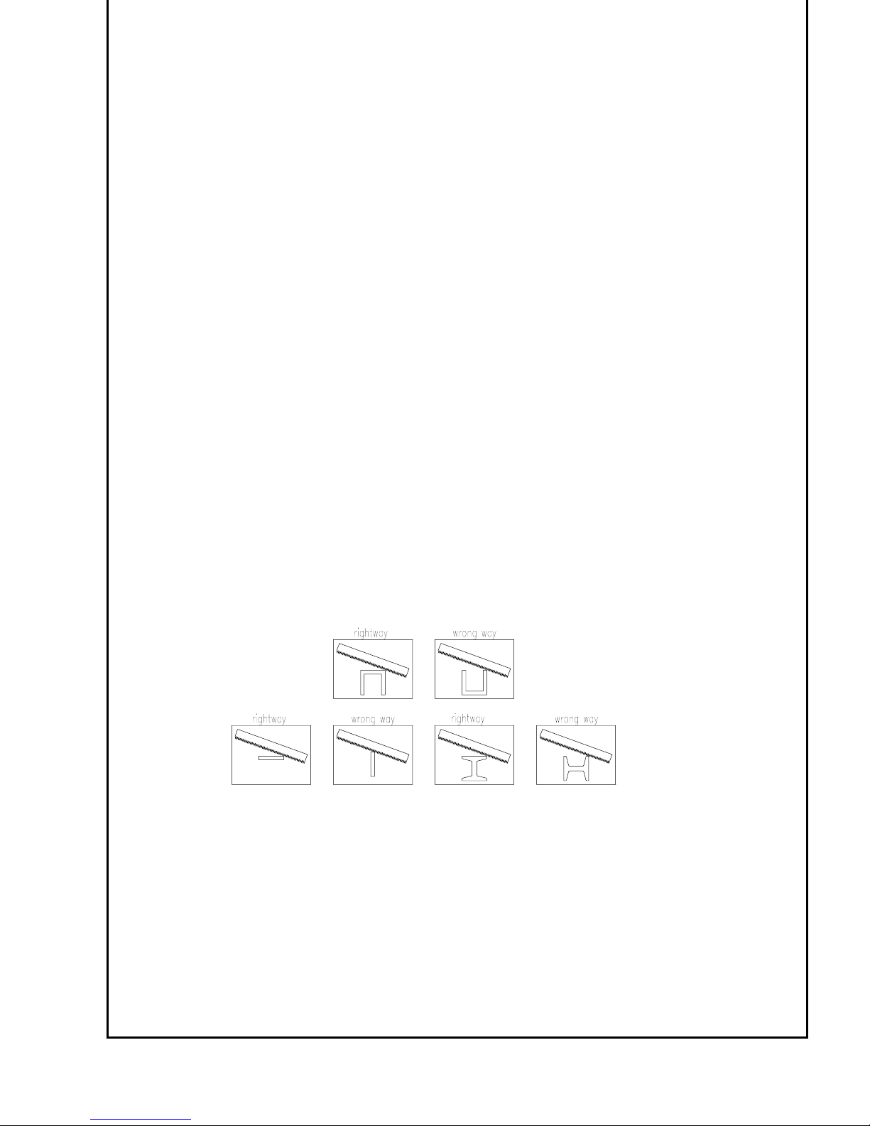
The proper cutting position for various shapes
x To stop the air motor release the valve lever.
x To stop the electric motor release the trigger.
x Saw band must be in motion before re-entering a cut.
To disconnect air hose shut main air hose valve.
Open air valve to decompress hose before disconnecting it.
To disconnect the electric motor unplug the cord from the power outlet.
7
Page 8
Troubleshooting
Problem:
Motor runs properly but cut is not sufficient.
Probable Cause
x Saw band is not sharp
Replace saw band
x Teeth point to the wrong direction
Remove saw band, change teeth direction, and install it again.
x Saw band is not tightened
Tighten saw band
x Saw band type (Material, TPI) is wrong for cutting
the material
Exchange saw band
x Cutting speed is wrong
Increase or decrease air flow pressure
x Saw band guide bearing or pulleys were not maintained sufficiently
after cutting in wet surrounding
Replace damaged parts
Problem:
Vibration
Probable Cause:
x Material to be cut is not firmly held
Clamp the material near the cutting location
x Fixed TPI instead of variable
Exchange saw band
Problem:
Motor does not start
Probable Cause:
x Low air pressure or volume
Check compressor and air hose valves as well as
air inlet screen for pollution
x Iced exhaust
Wait until ice-free, use anti-freeze lubricant
x Vanes sticky
Put air tool oil into air inlet and blow motor clear.
Repeat if necessary. Refer to Maintenance Instructions
Problem:
Electric Motor does not start
Probable Cause:
x Check power supply for blown fuses or open circuit breakers in the line.
x Check that switch is in “ON” position
x Check that power cord is plugged into outlet.
x Check that prongs on the cord plug are making good contact in the outlet.
8
Page 9
Changing Saw Bands
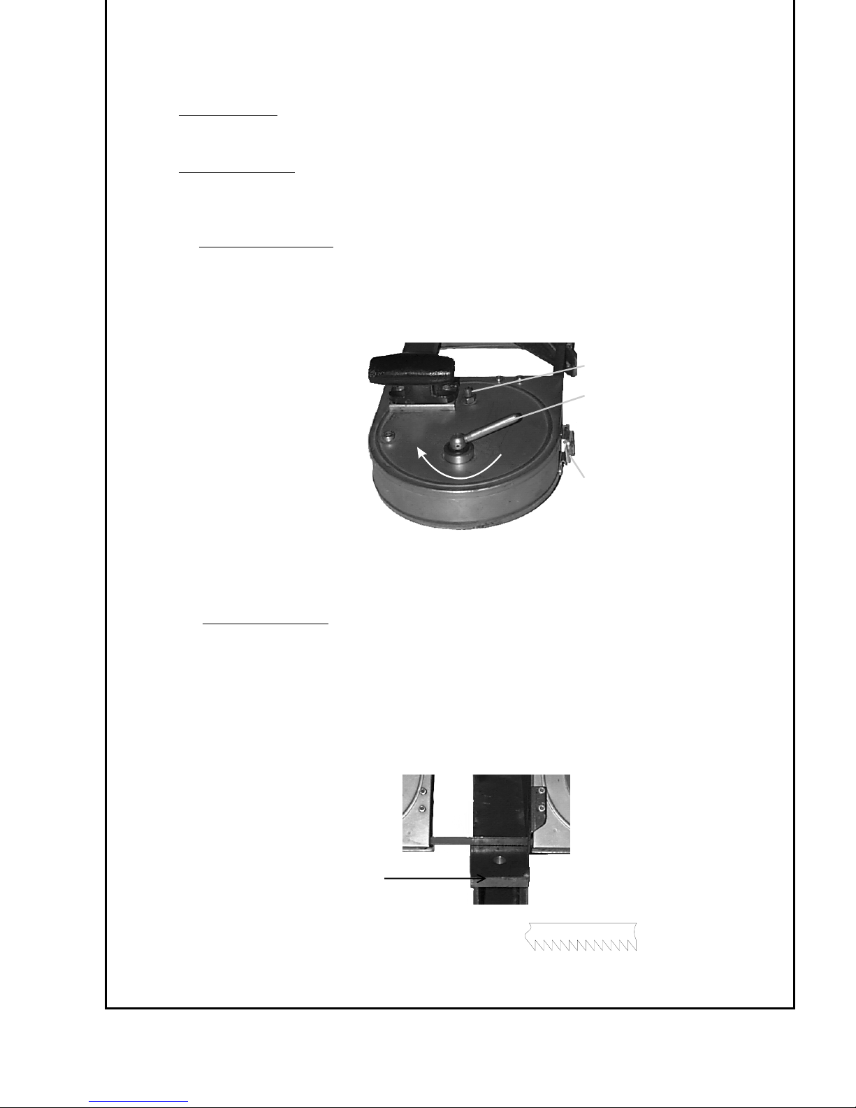
A
Observe the following safety instructions before changing saw bands.
Electric Motor:
1. Disconnect plug from power outlet
Pneumatic Motor:
1. Disconnect air hose
Open air valve to decompress hose before disconnecting it
To remove saw band
2.
Turn adjustment handle (A) clockwise to release tension on the saw band.
After that unlock closures (C) of the coating by turning and open the cover lid.
Remove the saw bands from tire pulleys and then from guide.
B
C
3. Before installing a new saw band, clean chips and wax, which may have accumulated
on guide and tire pulleys.
To install saw band
4.
Before installing the saw band check ease of guide bearings
Make sure teeth point in the right direction (see below)
Install saw band in guides and then position on pulleys.
Turn adjustment handle counter-clockwise as far as it will go.
Close cover lid, connect air hose and start and stop saw two or
three times to seat saw band on pulleys.
If the saw band fails to track correctly, adjust band tracking by means of
adjusting screw (B).
direction of band travel position of teeth
9
Page 10

Selection of Saw Band
Which saw band to use
In general, select a saw band which will allow at least two teeth to be
engaged in the material thickness. The thinner or the harder the material,
the finer the saw band teeth.
Ask your dealer for the right selection of saw bands.
WARNING:
Exercise extreme care to prevent hand from contacting the saw band
USE OF LUBRICANTS
NEVER USE LIQUID COOLANT WITH YOUR BAND SAW. Damage to
the blade guide bearings or rubber tires on the pulleys may result.
Warning: LIQUID COOLANTS CAN INCREASE THE RISK OF
ELECTRICK SHOCK. Use only stick wax to lubricate the blade.
CS Unitec’s “Lube Wax“ is availabe as an accessory and is recommended when
cutting aluminum, brass and thick materials. Cast iron should be cut dry.
With the saw running, apply the wax momentarily to both sides of the blade.
Reapply wax intermittently as needed.
Warning: EXCERISE EXTREME CARE TO PREVENT HANDS FROM
CONTACTING THE BLADE.
After prolong cutting, the wax will cling to the pulleys of your Band Saw. This
does not affect the operation of the machine. All that is necessary is to
disconnect the machine from the power source adn wipe the wax from the
pulleys.
10
Page 11
General Operating Instructions
AIR BAND SAW
1) Air Supply
Compressor must be able to supply the saw with at least 1,00 m³/min (35 cfm)
clean and dry air at 7 bar (100 PSI).
Install a service unit, if necessary, but in any case use an oiler.
Minimum air hose diameter 13 mm (1/2“).
Blow air hose clear and connect it to the cleaned saw air inlet
(Check screen).
Lubricator
2)
Install service units or line oiler!
Check and if necessary fill with resin- and acid-free SAE 5 W to SAE 10 W
oil.
In winter or when using very moist air, use antifreeze lubricant, such as
“Kilfrost”, “BP Energol AX 10” or “Kompranol N 74”.
3) Remember safety instructions and cutting hints!
ELECTRIC BAND SAW
1) Model 5 6047 0010 is designed for A.C. current only. Refer to the specification plate on your tool
to proper voltage and current rating.
CAUTION: Do not operate your tool on a current on which the voltage is not within
correct limits. Do not oeprate tools rated A.C. on only D.C. current. To
do so may seriously damage the tool.
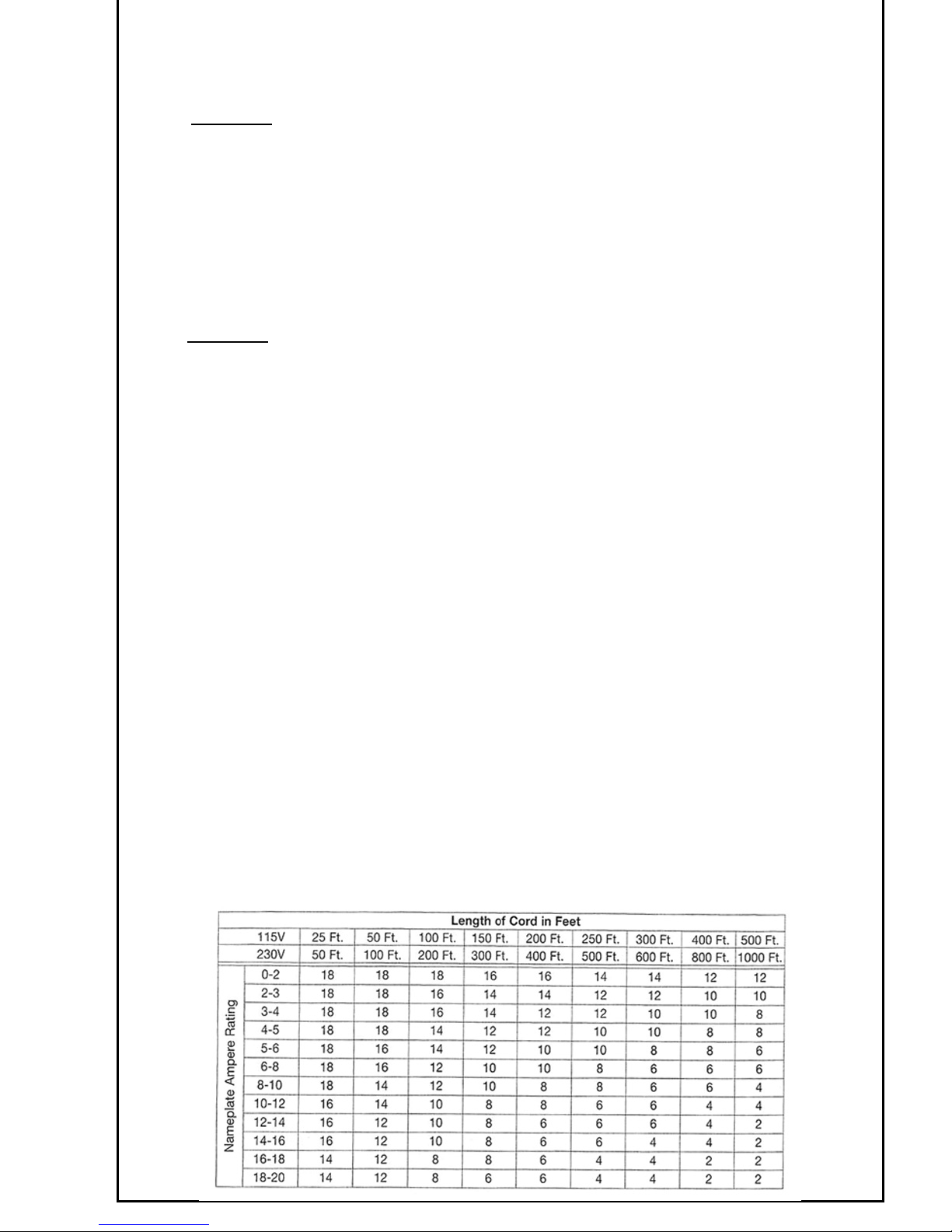
EXTENSION CORD SELECTION
If an extension cord is used, make sure the conductor size is large enough to prevent excessive voltage
drop which will cause loss of power and possible motor damage. A table of recommended extension
cord sizes will be found in this section. This table is based on limiting line voltage drop to 5 volts (10
volts for 230 volts) at 150% of rated amperes.
If an extension cord is to be used outdoors it must be marked with the suffix W-A or W following the
cord type designation. For example – SJTW-A to indicate it is acceptable for outdoor use.
RECOMMENDED EXTENSION CORD SIZES FOR USE WITH PORTABLE ELECTRIC BAND SAW
11
Page 12

Maintenance
Only proper maintenance can ensure constant performance, reduction in wear and thus,
a decrease in operating costs and an increase in service life.
AIR BAND SAW
SERVICE LIFE and PERFORMANCE of the Air band saw are determined by
a) Degree of air purity
Blow the air hose clear before connecting it to the saw.
Install dirt and water separators upstream of the saw, if it is not possible
to prevent the formation of rust and water condensation in the air distribution lines.
b) Lubrication
The motor must be lubricated by a line oiler or service unit.
Fill the lubricator with resin- and acid-free „SAE 5 W“ to „SAE 10 W“ oil.
Heavy oils will cause the vanes to stick, thereby making the motor difficult to start
and impairing its performance.
Optimum lubrication significantly prolongs service life. We therefore
highly recommend to install service units (combined filters, regulators and
lubricators) upstream of the saw.
c) Maintenance
Regularly check and clean the air inlet screen.
Replace wear parts - in particular the motor vanes - when necessary.
Vanes are considerd worn if their width is less than 9.7 mm (3/8“)
ELECTRIC BAND SAW:
For your continued safety and electrical protection, brush inspection and replacement
on this tool should ONLY be performed by an Authorized CS Unitec Service Station.
At approximately 100 hours of use, take or send your tool to your nearest authorized
CS Unitec Service Station to be thoroughly cleaned and inspected. Have worn parts
replaced and lubricate with fresh lubricant. Have new brushes installed, and test the
tool for performance.
Any loss of power before the above maintence check may indicate the need for
immediate servicing of your tool. DO NOT CONTINUE TO OPERATE TOOL
UNDER THIS CONDITION. If proper operating voltage is present, return your tool
to the service station for immediate service.
Keep Tool Clean
Periodically blow out all air passages with compressed air.
Caution: Wear safety glasses while using compressed air.
Remove wax and chip buildup from drive pulleys and blade guides.
All plastic parts should be cleaned with soft damp cloth. Never use solvents
to clean plastic parts. They could possibly dissolve or otherwise damage the
material.
After use, clean the saw. Rinse it with light oil or provide alternate corrosion
protection after having worked in wet surroundings.
12
Page 13
SERVICE AND REPAIRS OF
ELECTRIC BAND SAW
All quality tools will eventually require servicing or replacement of parts due to wear from
normal use. These operations, including brush inspection and replacement, should ONLY be
performed by an AUTHORIZED CS UNITEC SERVICE STATION. We cannot guarantee
repairs made or attempted by anyone other than these agencies.
Should you have any questions about your tools, feel free to call us at any time. In any
communications, please give all informaiton shown on the nameplate of your tool.
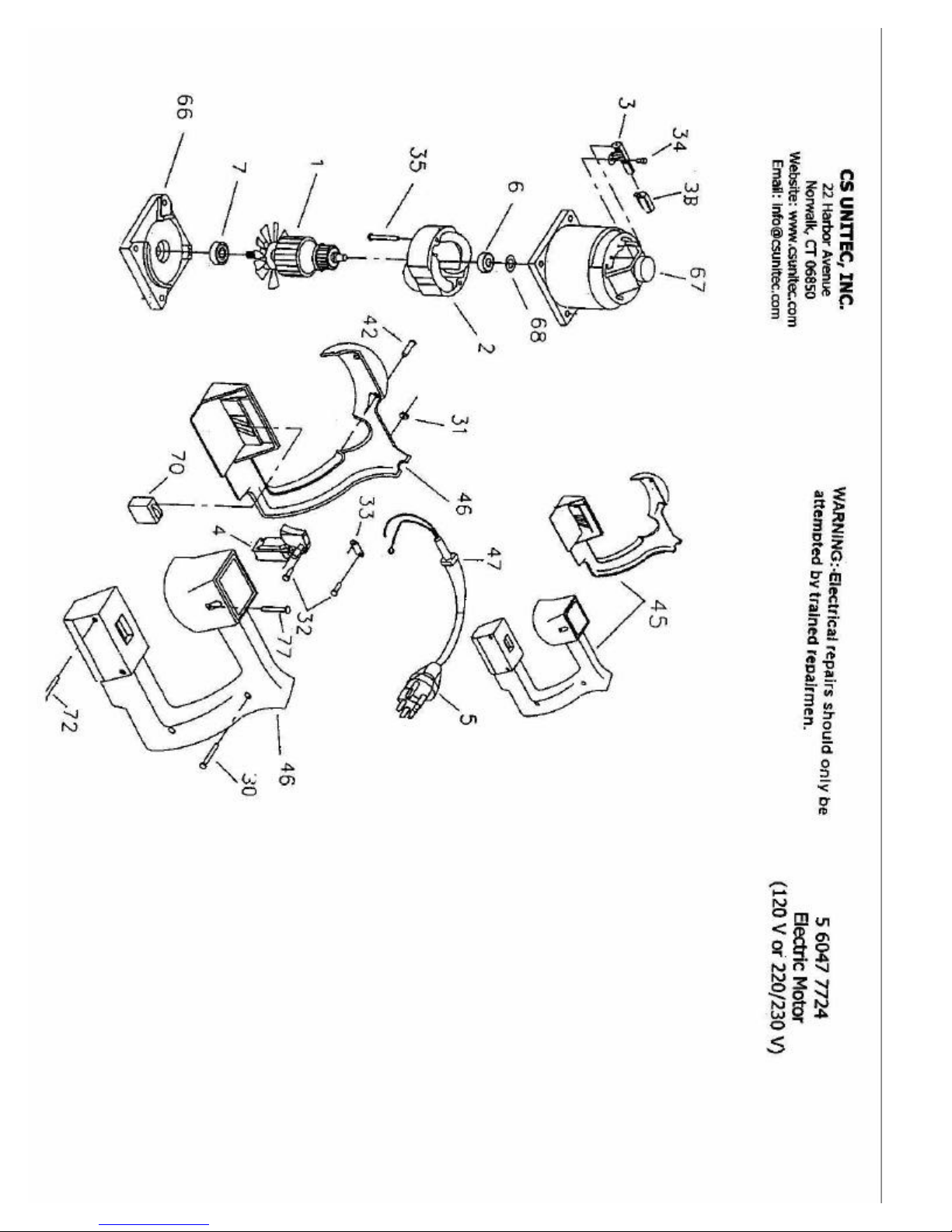
WARNING: Electric reparis should only be attempted by a trained repairman.
DISASSEMBLY AND REASSEMBLY
OF THE AIR BAND SAW
Refer to the sectional drawing and to the spare parts list when disassembling
and reassembling.
Remove motor with handle from band saw head after undoing screws (77).
Diassembly of Motor (for changing the vanes)
Unlock locking ring (18) and take out front motor component consisting of thrust collar
(16), Belleville spring (17) and shaft seal ring (20) with ring (19).
Touch the motor housing softly to a wooden surface to pull out inner motor parts.
Pull off end plate (12) with bearing (13), snap ring (14) and spacer (15) from rotor (10)
and take out locking pin (8). Disassemble snap ring (14) and take out bearing (13).
Remove cylinder bushing (6 ) and vanes (11). Pull off end plate (2) with bearing (3) and
spacer (5) from rear rotor seat (10). Unlock snap ring (4) and disassemble bearing (3.)
Remove sound absorber (9).
Screw off silencer (22).
Reassembly of Motor
Reassembly is performed essentially the same as disassembly, but in reverse order. Inspect
all parts for wear and damage. Replace any worn or damaged parts.
Vanes (11), should be exchanged.
Vanes are considered worn if their width is less than 9.7 mm (3/8“)
Disassembly of Handle
Untighten screw plug (37). Remove spring (35), ball (34), seal (32) and cylindrical
pin (33).
Hit out double notched pin (31) and remove Pusher (30).
Take out screw plug (40), spring (39) and locking bolt (38).
Reassembly of Handle
Reassembly is performed in reverse order.
13
Page 14
DISASSEMBLY AND REASSEMBLY
OF THE AIR BAND SAW
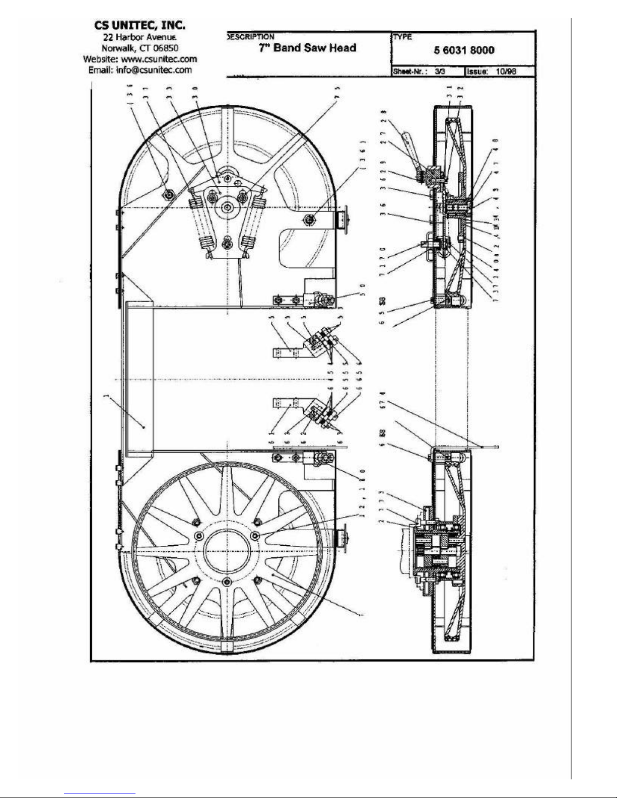
Disassembly of Band Saw Head
Undo screws (12 and 42) and detach pulleys (7 and 40) with tire pulleys.
After undoing screw (47), detach washer (48), needle bearing (43) and washers (44 and
45). Unscrew hexagonal nut (72), and remove washer (73).Undo hexagonal nut (71) and
screw out threaded pin (70). Loosen screw (32) and pull out washer (31). Pull out tension
shaft (27) and knob (28). Remove pin (29) and separate knob (28) from tension shaft (27).
After loosening hexagonal nuts (75) pull out washers (73) remove yoke (30) as well as
spring (37) and washer (33). Undo screws (59 and 69) and remove stop (74) and guides
(50 and 60).
Reassembly of Band Saw Head
Ressembly is performed essentially the same as disassembly, but in reverse order.
Control function by moving pulleys (7 and 40) before connecting the motor.
For disassembly of the gearbox undo screws (12) and remove pulley (7).
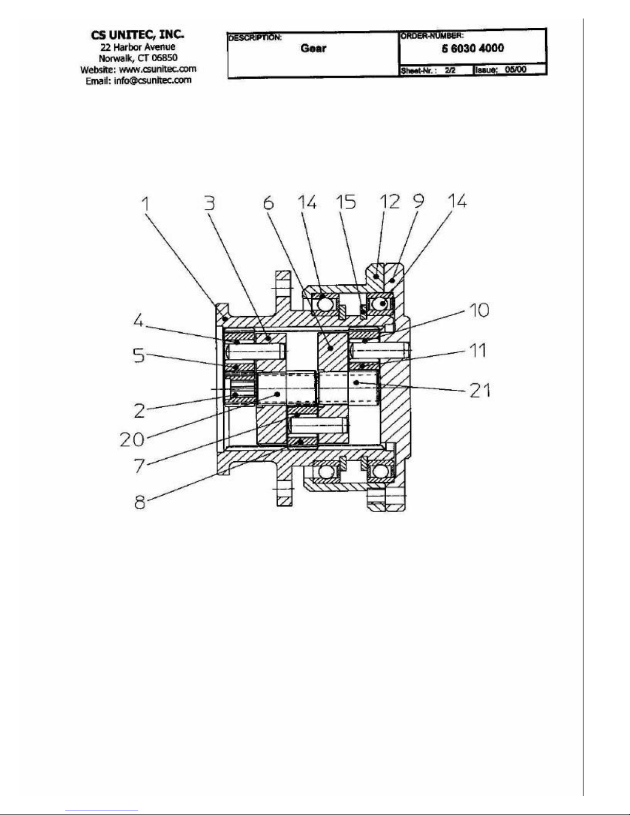
Disassembly of the Gearbox
Pull off planet carrier (9). Take out all gearbox stages and remove planetary wheels (5, 8,
11) and needle bearings (4, 7, 0). Take out bearing (14). Remove snap rings (15) and pull
out bearing ring (12) with second bearing (14). Separate pinion (20, 21) from planet
carrier (3, 6).
Reassembly of Gearbox
Reassembly is performed essentially the same as disassembly but in reverse order.
Add sufficient grease to gearbox.
Spare parts and Service
Only ORIGINAL SPITZNAS SPARE PARTS have to be used.
SPITZNAS takes out any liability for damages which have occured by use of not approved
parts or accessories.
Intended purpose
Safe operation is only ensured, when the band saw will be used solely for that purpose
defined in the Operating Instruktions.
General
For proper use read and follow Operating Instructions of the band saw 5 6031 0010 in any
case.
14
Page 15
Page 16
Page 17
Page 18
 Loading...