

OPERATING AND MAINTENANCE
MANUAL
PETROL COLD WATER MODELS
8-140P 11-140P 13-200P 15-250P HP152/A HP251/A HP251AE
HP201SAE HP251SAE HP3523AE HP2430AE
Made By:
Spitwater Australia Pty Ltd
953 Metry St
North Albury , NSW , Australia
WARNING:
FAILURE TO FOLLOW OPERATING, SAFETY AND MAINTENANCE
INSTRUCTIONS LISTED IN THIS MANUAL RELEASES THE MANUFACTURER
FROM ANY RESPONSIBILITY FOR ACCIDENTS OR DAMAGES TO BOTH
HUMANS AND OBJECTS AND MAY RENDER ANY WARRANTY VOID


3
TECHNICAL DATA
INTRODUCTION
The SPITWATER range of high pressure cl eaners has been designed to give safe, efficient and reliable service. Like any other
piece of equipment; however, the unit will only operate at maximum efficiency if the corr ect operating sequences are foll owed and
proper attention is given to the maintenance procedures.
The purpose of this manual is to provide u p to date information necess ary to the user for operating, mai ntaining and servicing the
unit, together with fault finding techniques and ge neral specificatio n details and diagr ams. The informatio n given, however, m ay be
subject to revision in compliance with the policy of continual improvements.
HEALTH AND SAFETY AT WORK
Manufacturers and suppliers of products for use in the w orkplace have a duty to ensure, so far as is reasonably practicable, that
such products are safe and without ris k to health when properly used and to make available to users of s uch products adequate
information about their safe and proper operation.
The SPITWATER range of high pressure cleaners should only be use d in the manner and purpose for which they were intende d
and in accordance with the recomm endation detailed in this Manual and in any other Governm ent Standard applicable in your
country. Our units have been designed, produced and inspected wi th safety in mind; however, there are certain basic precautio ns
which should be taken by the user and in particular, attentio n is drawn to t he safety prec autions in this Manual and in the Ope rating
Instruction stickers on the unit itself.
It is imperative therefore, that all persons who m ay make use of this unit, have a ll the information and instructions th ey require to
ensure that they are fully aware of t he hazards and they know both t he purpose and correct man ner of operation of our pressure
cleaners.
Model
8-140P 11-140P 13-200P 15-250P HP152/A HP251/A HP251/AE HP201S AE HP251S AE H P3523A E
Flow Ra te
L/M-L/H 8-480 11-660 13-780 15-900 12-720 15-900 15-900 21-1260 21-1260 23-1380
Pressure
Working Bar-Psi 140-2100 140-2100 200-3000 250-3650 150-2250 250-3650 250-3650 200-3000 250-3650 350-5000
EW E R otojet Bar-Psi 185-2775 185-2775 255-3825 300-4500 195-2925 300-4500 300-4500 255-3825 300-4500 400-6000
Ma x In let
Pressure Bar-Psi 10-150 10-150 10-150 10-150 10-150 10-150 10-150 10-150 10-150 10-150
Temperature
0
C
50 50 50 50 50 50 50 50 50 50
Pu m p Moto r
Power kW -HP 4.1-5.5 4.1-5.5 6.6-9 9.6-13 4.8-6.5 9.6-13 9.6-13 9.6-13 13.4-18 18-24
Make HONDA HONDA HONDA HONDA HONDA HONDA HONDA HONDA HONDA HONDA
Tank Capacity L 4.3 4.3 6 6.5 3.6 6.5 6.5 6.5 11 11
Petrol Type Unleaded Unleaded Unleaded Unleaded Unleaded Unleaded Unleaded Unleaded Unleaded Unleaded
Sta r tin g S y s te m Pu ll Start Pu ll S ta r t Pull S ta r t Pull S ta rt Pu ll Start Pull S ta r t Elec tr ic S ta r t Ele c tric Start Electric Start Elec tr ic S ta rt
Pro t e ctio n Oil G uard Oil Gua rd O il Gua rd O il Gua rd Oil Gua r d Oil Gua rd Oil Guar d Oil Gua rd Oil Gua rd Oil Gua rd
Pump
Model TT1511 UH2013 WS251 W140 WS251 WS251 WS202 WS252 W3523
Rpm 3400 3400 3400 1450 1450 1450 1450 1450 1450 1450
Oil Capacity l 0.33 0.4 1.2 0.4 1.2 1.2 1.2 1.2 1.2
Oil Type SAE 20-30 20-30 20-30 20-30 20-30 20-30 20-30 20-30 20-30 20-30
Hose Length
3/8
M 8 8 8 10 10 10 10 10 10 10
Dimension
L x W x H mm. 500X490X940 500X490X940 600X 580X 1040 920X630X 860 790X535X 723 920X630X 860 920X630X860 920X630X860 985X750X950 985X75 0X950
Weight
kg 34 34 51 83 51 83 83 97 114 118
The Manufacturer reserves the right to modify design features and technical data without notice

4
IMPORTANT SAFETY INSTRUCTIONS AND PRECAUTIONS
This booklet contains important information for the use and safe operation of this high pressure cleaner. Read and understand all
warnings before you start using the unit.
WARNING: When using this high pressure cleaner:
1. Read all instructions before using this high pressure cleaner (Including the engine instructions booklet).
2. Know how to start and stop the unit and bleed pressure quickly. Be quite familiar with the controls.
3. Follow the maintenance and faultfinding procedures outlined in this manual.
4. Keep operating area clear of all persons.
5. To prevent fire hazards, do not use near inflammables such as: gasoline, grain dust, solvents, thinners etc.
6. Stay alert and hold the lance strongly as high pressure cleaner jets produce a strong reaction force
7. This unit is not to be operated by children, teenagers or impaired persons (ie. people under the influence of drugs,
alcohol etc).
8. Do not overreach or stand on unstable supports.
9. To reduce the risk of electric shock/damage do not aim the water jet onto the unit or any other electrical part and
always wear rubber-soled footwear when operating the unit.
10. Keep the unit in a dry building where there is no danger of freezing.
11. Do not exceed the maximum temperature and pressure indicated in the technical data.
12. Never aim the jet in the direction of human beings, because the water jet comes out of the nozzle at high speed with
high pressure.
13. Do not pull on high-pressure hose in order to move the unit.
14. Use only high-pressure hoses supplied by Spitwater Australia. In the case of defects, never try to bind up defective
hoses, replace them.
15. Do not work in the rain or during thunderstorms.
16. When the unit is working, do not cover and do not place in a closed space where ventilation is insufficient.
17. Do not operate this unit in enclosed spaces.
18. Do not leave the unit running unattended. If unit is not required please switch it off.
19. When finishing work, always secure the handpiece with the lock catch.
20. To prevent injuries always turn the machine off before disassemblin g any part of the unit or effecting any servicing
and before leaving the machine.
21. All serious servicing and maintenance procedures should be carried out by an aut horised servi ce per son using spare
parts supplied by Spitwater Australia.
22. Local regulations and standards as to the installation and operation of high-pressure cleaners must be observed.
WARNING: RISK OF INJECTION OR INJURY - DO NOT DIRECT HIGH PRESSURE JET STREAM AT PERSONS
SAVE THESE INSTRUCTIONS
READ WITH ATTENTION THE WARRANTY CARD AND MAIL COPY ON THE DATE OF SALE
5
INSTALLATION AND OPERATING INSTRUCTIONS
INSTALLATION
1. Identify your unit from the model description on the ser ial no. / data plate label affixed on the High press ure cleaner and the
exploded views contained in this manual. (ALL NUMBERED REFERENCES APPLY TO EXPLODED VIEW OF UNIT)
2. (If necessary) Fit handle (3) to frame using bolts supplied in accessories bag.
3. (If necessary) Fit hoses (63) (28) (61) to break tank tailpie ces (48) using hose clamps provided in accessories bag.
4. Position unit on a level surface near a suitable water s upply (see serial no./ data plate)
5. (If Necessary) Connect front part of lance (33) to back part of lance (26).
6. Connect high-pressure hose end (30) t o Back part of lance (26) and unit high-pressure outlet (21)or (A) or (62).
7. Connect water supply hose to inlet co nnector (18) supplied. Make sure t hat water pressure does not excee d values listed in
this manual and that water flow rate after inlet / cistern cock valve exceeds the one required by the pump as stated on serial
no. / data plate.
8. Open water supply. Where a water tank is fitted, water will fill water tank (20) and cist ern cock valve (45) will automatically
stop water flow when water tank is full.
9. Replace the pump oil travel plug (Red plu g) with the pump oil dipstick (Yellow plug) provided in accessories bag.
10. Check oil level in pump either using dipstick or through oil sight glass. Minimum oil level is at lower edge of red circle on sight
glass or lower notch on dipstick while maximum o il l evel is at up per e dge of red c ircle on sig ht gl ass or up per notc h on dips ti ck.
If oil reservoir needs replenishing only use o il of a type as listed in the data sheet in this instruction man ua l.
11. Follow all pre operation instructions liste d in the petrol engine manual supplied with this unit.
12. Where fitted fill detergent bottle (11) with cleaning solution. Only us e a cleaning detergent approv ed by the manufacturer and
do not use under any circumstance acid or corrosive products (Contact an author ised service agent or the manufacturer if i n
doubt).
13. Set lance assembly (26 ,33)in the low pressu re position. See pt 5 instructions on Operating/To start & use instructions.
OPERATING INSTRUCTIONS
TO START AND USE
1) Start machine by following Starting & Operating instructions listed in engine manual supplied with this unit. Pull the tri gger on
the handpiece and allow water to run through the Pump (14), High-Pressure Hose (30), and Lance for 2-3 minutes in order to
expel air from the Hydraulic system. If some air is still in the system after that period of time, open and close the Handpiece 23 times to expel remaining air. Note: if this is the first time the unit is being run or it has been left idle for a long period
of time it is advisable to run the above operation with the front part of lance (33) or nozzle (56) disconnected from the
lance to avoid any debris / scale getting lodged in the nozzle and/or gun assembly.
2) Set the front part of lance (33) in high pressure position. See pt 5 instructions on the Operating/To start & use instructions.
3) Check if pressure on Pressure Gauge (29) is correct. (See data plate on pump).
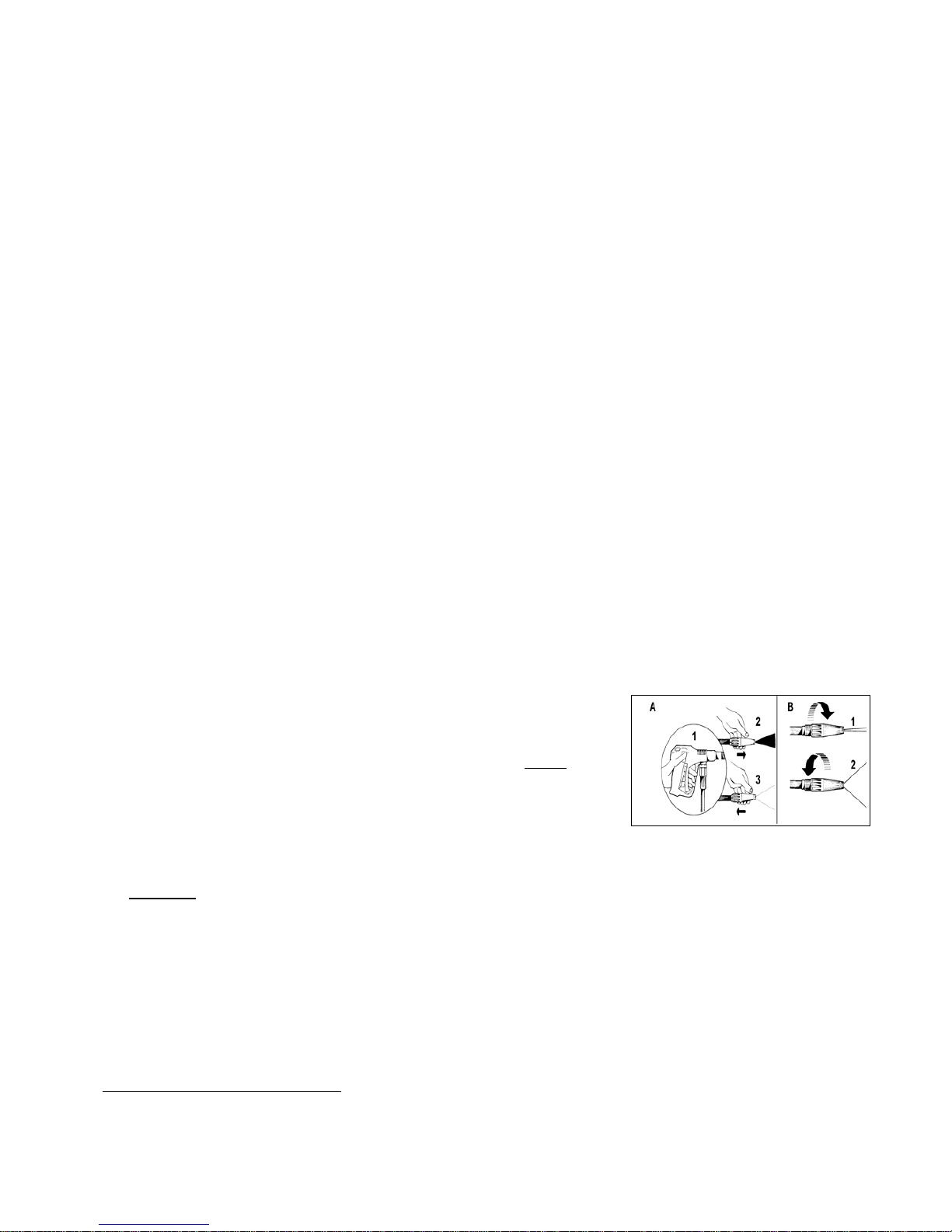
4) Multireg nozzle can be adjusted anyw here to provid e a jet between 0
0
and 450 and
high/low pressure so as to suit any cleaning application. By turning nozzle
clockwise/anticlockwise you can decrease/increase size of fan as shown in pictur e
beside (B). By pushing nozzle backward/forward with gun in closed
position
you can go into low pressure/high press ure as shown in picture beside (A).
Double lance can be adjusted between high/ low pressure by turning the handle
clockwise/anticlockwise.
7) To allow detergent through injection system, turn Chemical injector (21 or red knob on pump) anticlockwise and put Multireg or
double lance in low pressure position. Pull trigger of Handpiece and low pressure will allow detergent through injection system.
NOTE: DETERGENT INJECTION CAN BE MADE IN LOW PRESSURE ONLY.
8) BEWARE :
Units not fitted with a break tank or optional Thermal Protection valve must not be run for longer than 3
minutes with Handpiece in closed position ( in Bypass) because pump will be damaged. If unit is not required please
switch it off.
TO STOP
1. Clean Detergent Line (25-23) after removing from detergent bottle in order to prevent blockages in chemical i njection device by
dropping detergent line in clean water and running clean water through it. (For instructions on how to run clear water through
detergent line see point no. 7 above on how to use detergent.)
2. Stop detergent flow, turning Chemical injector (21 or Red Knob on pump) clockwise.
3. Stop machine by following Stopping instructions listed in engine manual supplied with this unit.
4. Pull trigger of Handpiece to release pressure.
OPTIONAL EXTRAS (WHERE FITTED)
ELECTRIC START
1. General operation of unit is the same as above but it will be possible to start the engine using a key switch. Follow instructions
on how to connect battery and use electric start listed in engine manual provided with this unit

6
MAINTENANCE INSTRUCTIONS
To maintain your unit in peak working condition during its operable life it is necessary to carry out regular maintenance operations
and replace worn or broken down parts immediately upon their failure. We suggest that a qualified service person carries out all
maintenance and that original spare parts are used in effecting repairs to guarant ee quality, reliability and longevity. Failure to
follow the above instructions releases the manufacturer from any responsibility in reference to injuries and damages to
both persons and goods and may render any warranty given with the units void.
Please find below a summary table of maintenance operation with a general description on how they should be carried out:
CHECKS TO BE CARRIED OUT BY USER
GENERAL
1) Water connections/connectors/lines(Each use)
a) Check high-pressure hose, connectors and other connections for leaks.
b) Check inlet hose connections for leaks.
2) Performance (each use)
a) Check machine functionality (ie. operation, pressure etc.) and performance and make sure that everything operates as
described in the operating instruction. Should any malfunction occur, stop operating the unit immediately and
contact an authorised service person/agent.
3) Nozzle (every 50 hours)
a) Check and clean high-pressure nozzle (56). It is necessary in situations where dirty or contaminated water is used that
nozzle be cleaned more regularly.
4) Filters (Every 100 hours)
a) Check and clean water filter (47) Replace every 1000 hours
b) Check and clean detergent filter (25).
5) Water and Detergent Lines
a) Unit should never be stored in areas where freezing conditions can occur unless all water has been expelled from all
hydraulic lines (ie. inlet, pump, coil hp hose e tc) and detergent lines or an appropriate anti freeze so lution has been
circulated in the above lines; contact your service agent for appropriate instructions. Failure to follow above guidelines
will result in great damage occurring to unit.
b) Keep detergent line clean (23,25) and make sure it is regularly flushed especial ly if machine is not used regularly.
PUMP
1) Oil (each use)
a) Check oil level in pump either using dipstick or through oil sight glass in back of pump. Minimum oil level is at lower edge
of red circle on sight glass or lower notch on dipstick while maximum oil level is at upper edge of red circle on s ight glass
or upper notch on dipstick. If oil reservoir needs replenis hing only use oil of a type as listed in data sheet in this instruction
manual.(Only use SAE20 W 30 oil)
b) Check that oil colour has not gone milky. If so do not operate unit and contact an authorised service agent immediately.
c) Replace oil after first 50 hours of operation and every 200 hours after first change or once per year.
To replace oil remove oil plug C and oil dipstick B and let oil fall into container until completely
drained. After oil has completely drained replace oil plug C and refill using only SAE 20 W 30 oil until
mark on sight glass A or oil dipstick B has been reached. Dispose of waste oil according to local
regulations and standards.
2) General
a) If unit has been left unused for long periods of time, before restarting unit a few drops of oil should
be placed on the pump vents to lubric ate the seals at start up. ( Note that not all pumps are fitte d
with these vents )
ENGINE
1) Carry out all user checks and maintenance as outlined in the engine instruction manual at the suggested intervals.

7
CHECKS TO BE PERFORMED BY AUTHORIZED SERVICE PERSON/AGENT
Checks and interval times at which checks should carried out and performed by an authorised servic e person/agent are
summarised below. It is essential that such checks and repairs be carried out by an authorised service person/agent as they have
the necessary experience and training required.
SUMMARY OF CHECKS TO BE CARRIED OUT BY THE USER SUMMARY OF CHECKS TO BE CARRIED OUT BY AN AUTHORIZED
SERVICE PERSON/AGENT
Power cable/water connections/ hp
hose/performance
Each use Engine See Booklet
Engine See Booklet Check and if necessary replace pump
seals
Each 750 hours
Nozzle clean and inspect Each 50 hours Replace High pressure nozzle Each 200 hours
Water and Detergent lines Each 50 hours Check Settings of all Hydraulic line
safety mechanisms
Once per year or every
500 hours whichever
comes first
Filters Each 100 hours
Pump oil first change After 50 hours
Pump oil change first / after first Each 200 hours
Others checks See Above
NOTE:
1) Time indication for checks and replacement listed above are for units subject to normal operating conditions. Should
unit be subject to abnormal conditions ( ie. heavy duty use, dirty water or fuel, extreme temperatures or climatic
conditions etc.) times should be reduced accordingly
2) Should unit be subject to very limited use, all checks and if necessary replacements should be carried out at least
once per year.
TROUBLESHOOTING
FAULT CAUSE REMEDY
Pump Sucking air Check that hoses/ fitting on inlet side of pump are airtight.
Nozzle is blocked Check and clean nozzle
The pump is running normally but pressure
does not achieve rated values
Water filter dirty Check and clean water filter
Pump Sucking Air Check that hoses/ fitting on inlet side of pump are airtight.
Fluctuating Pressure
Water filter dirty Check and clean water filter
Pressure drops after a period of normal use Contact authorised serve person/agent
Pump Sucking air Check that hoses/fitting on inlet side of pump are airtight.
Pump is noisy
Water inlet is too hot Reduce water inlet temperature below 50
0
C
Presence of water in pump oil Contact authorised service person/agent
Water dripping from under pump Contact authorised service person/agent
Oil dripping from under pump Contact authorised service person/agent
Presence of water in gearbox oil Contact authorised service person/agent
Oil dripping from under gearbox Contact authorised service person/agent
Engine does not start/operate correctly Refer to engine instruction book Contact authorised service person/agent
NOTE: If the fault cannot be identified or corrected using the above list (or in the remedy column the words “contact
Authorised service person/agent” appear) stop using the machine immediately and contact an authorised s ervice person
/agent to rectify the fault.
HYDRAULIC DIAGRAMS
D
G Handpiece trigger
S2 Detergent ta n k
F Filter
Aq Water inlet
M Motor
P Pump
V Bypass valve
D Detergent tap
U Nozzle
Aq
M
F
S2
P
V
Cold Water U nits Without Break Tank.
F
G
U
D
D Detergent tap
G Handpiece trigger
S2 Detergent tank
F Filter
S1 Break ta n k
Aq Wate r in le t
M Motor
P Pump
V Bypass valve
U Nozzle
AqS1N
M
F
S2
P
V
Cold Wa te r U n its F itte d With Break Ta n k .
F
G
U

8

9

10
11

12
13
14

15

16
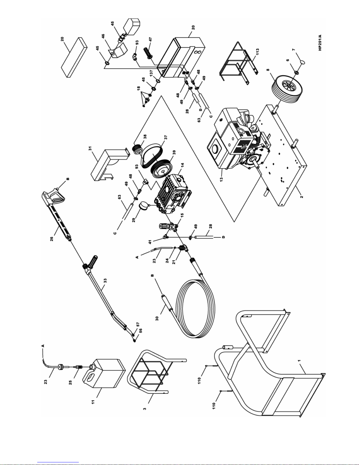
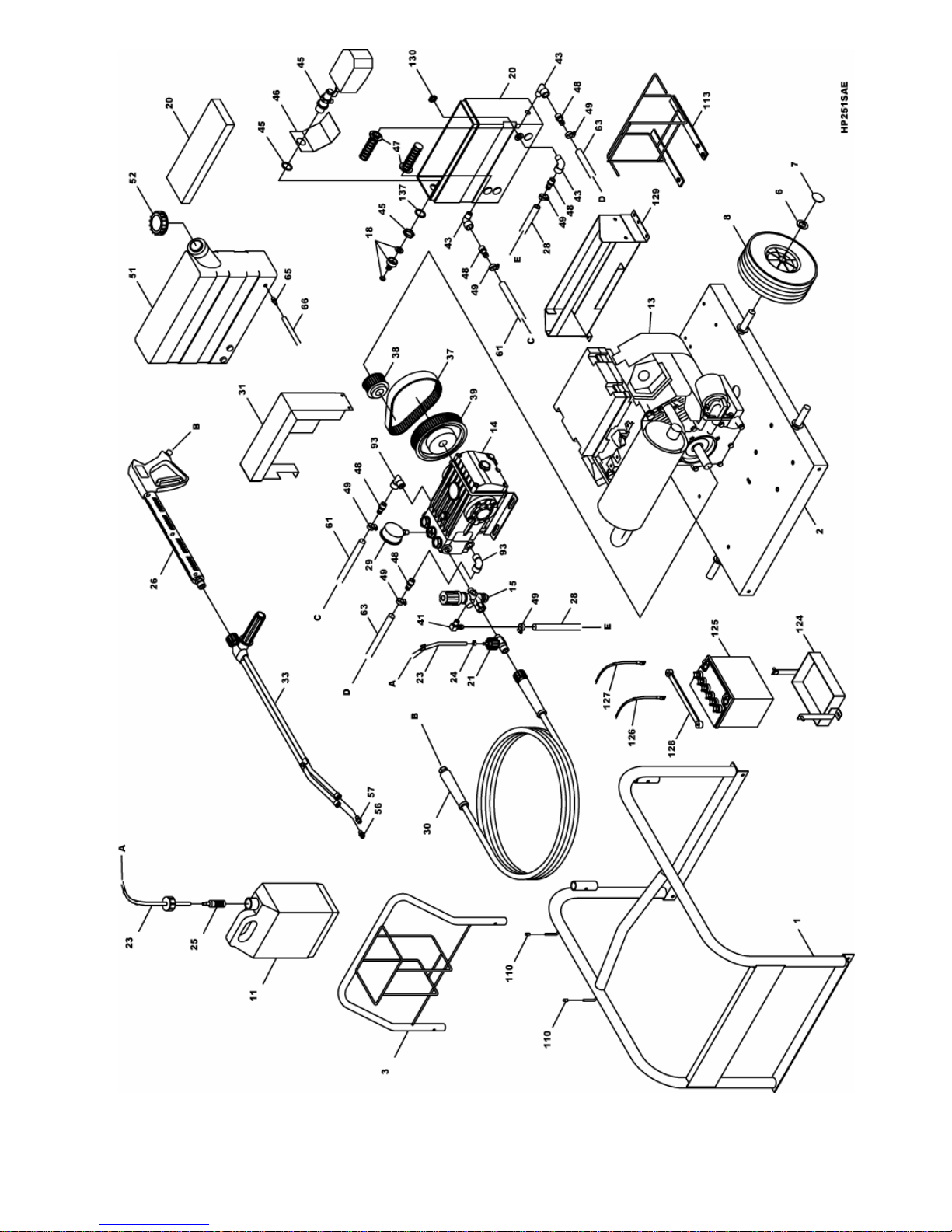
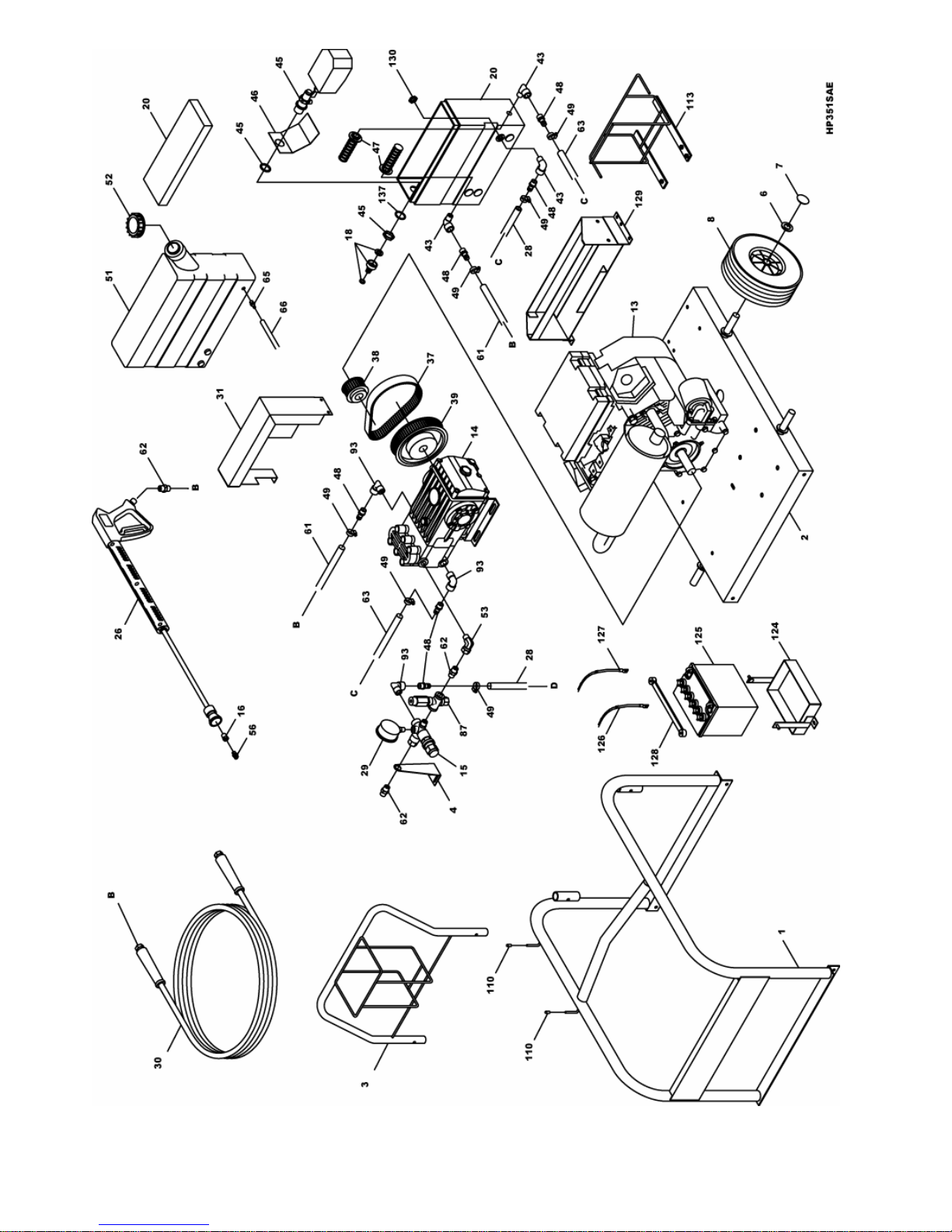
PARTS LISTING
NO DESCRIPTION 11-140P 13-200P 152/A 251/A 201SAE 251SAE 351SAE 2430AE
SLD04/A SLD15 SCWA50/A SCWA60 SCWA62 SCWA61 SCWA59 SCWA63
1 ROLL FRAME = = = = 1 48015/A 1 48015/B 1 48015/B 1 48015/C 1 48015/C 1 48015/C
2 FRAME 1 48987 1 48989 1 48023 1 48024/A 1 48024/A 1 48024/C1 1 48024/E1 1 48024/E1
3 HANDLE 1 48988 1 48990 1 48110/A 1 48110/B 1 48110/B 1 48110/C 1 48110/C 1 48110/C
4BRACKET ============140552==
6 WASHER 2 70200/P 2 70200/P 4 70200/P 4 70200/P 4 70200/P 4 70200/P 4 70200/P 4 70200/P
7 HUB CUP 2 47044 2 47044 4 47044 4 47044 4 47044 4 47044 4 47044 4 47044
8 WHEEL 2 47045 2 47045 4 47045 4 47045 4 47045 4 47045 4 47045 4 47045
11 DETERGENT BOTTLE = = 1 47002 1 47002 1 47002 1 47002 1 47002 = = 1 47002
13 MOTOR 1 48328/A 1 47153 1 47151 1 48330 1 48830/A 1 48902 1 48901 1 48901
14 PUMP 1 IPP142 1 IPP143 1 IPP83/A 1 IPP150 1 IPP44/A 1 IPP151 1 IPP137/A 1 IPP146
15 BY PASS = = = = 1 48236/C 1 48238/C 1 48236/C 1 48238/C 1 PA60180000 1 48238/C
16 BRASS REDUCER 1 47013 1 47013 = = = = = = = = 1 48945 = =
18 TAILP I ECE COMPLETE AU/NZ 1 70559 1 70559 1 70559 1 70559 1 70559 1 70559 1 70559 1 70559
20 BREAK TANK = = = = 1 48033/D 1 48033/G 1 48033/A 1 48033/A 1 48033/A 1 48033/A
21 CHEMICAL INJECTOR = = = = 1 47018/B 1 48235 1 48259 1 48259 = = 1 48259
23 DETERGENT HOSE 1 44539/C 1 44539/C 1 44539/A 1 44539/B 1 44539/B 1 44539/B = = 1 44539/B
24 HOSE CLAMP = = = = 1 46240 1 46240 1 46240 1 46240 = = 1 46240
25 DETERGENT FILTER 1 46241 1 46241 1 46241 1 46241 1 46241 1 46241 = = 1 46241
26 LANCE-B/PART WITH GUN 1 SWA05 1 SWA05 1 SWA05 1 SWA05 1 SWA05 1 SWA05 1 PA30455008 1 SWA05
28 BY PASS HOSE = = = = 1 48790/A 1 48796 1 48796 1 48790/D 1 48790/D 1 48790/D
29 PRESSURE GAUGE 1 47104 1 47105 1 47105 1 44390 1 44390 1 44390 1 44390/B 1 47105
30 HI GH PRESS. HOSE 1 48749 1 46604 1 44331 1 46605 1 46605 1 46605 1 46605 1 46605
31 BELT GUARD = = = = 1 1 48758 1 48758 1 48798 1 48800 1 48800/A
33 FRONT PART LANCE 1 SWA12 1 SWA12 1 SWA12 1 SWA07 1 SWA12 1 SWA07 1 = 1 SWA07
37 BELT = = = = 1 70630 1 70630 1 70630 1 70630 1 70631 1 70631
38 PULLEY = = = = 1 70600/A 1 `70600 1 70600 1 70600 1 70601 1 70601
39 PULLEY = = = = 1 70602 1 70602 1 70602 1 70602 1 70602 1 70602
40 THERMAL PROTECTOR 1 47400 1 47400/A = = = = = = = = = = = =
41 ELBOW 1/4M-1/2BARB = = = = 1 48333 1 48333 1 48333 1 48333 = = 1 48333
42 FLANGE 1 I10034622 1 I10061722 = = = = = = = = = =
43 ELBOW 3/8M-3/8F = = = = 48774 = = = = 3 48774 3 48774 3 48774
45 CISTERN COCK VALVE = = = = 1 48531 1 48531 1 48531 1 48531 1 48531 1 48531
46 SPLASH PROTECTION = = = = 1 48875 1 48875 1 48875 1 48875 1 48875 1 48875
47 WATER FILTER W/ADAPTOR 1 I92892500 1 I92892500 1 48767 1 48784 2 48784 2 48784 2 48784 2 48784
48 TAILP I ECE 3/8 = = 3 48775 3 48775 5 48775 5 48775 6 48775 5 48775
49 HOSE CLAMP = = 4 70597/C 4 70597/C 6 70597/C 6 70597/C 6 70597/C 6 70597/C
50 TAILPIECE 1/2 = =
51 FUEL TANK = = = = = = = = = = 1 48030/A 1 48030/A 1 48030/A
52 CAP = = = = = = = = = = 1 48750 1 48750 1 48750
53SWIWEL M/F 3/8 ======= ==== = 148991==
56 HI G H PRESSURE NOZZLE 1 I98663200 1 I98663200 1 I98663200 1 47021/0415 1 I98682000 1 47021/5515 1 47021/0415 1 47021/0825
57 LOW PRESSURE NOZZLE = = = = = = 1 46217 = = 1 46217 = 1 46217
59 HIGH PRESS. HOSE = = = = 48709/A
61 SUCTION HOSE = = = = = = = = 1 48791/C 1 48791/D 1 48791/D 1 48791/D
62 NIPPLE M/M 3/8-3/8S = = = = = = = = = = = = 3 48992 = =
63 SUCTION HOSE = = = = 1 48791/A 1 48795 1 48795 1 48796/C 1 48796/C 1 48796/C
65 TAILP I ECE 1/8 = = = = = = = = = 1 44541 1 44541 1 44541
66 FUEL HOSE = = = = = = = = = = 1 48907/B 1 48907/B 1 48907/B
67 REDUCER M/F 3/8-1/4 1 48766 1 48766 = = = = = = = = = = 1 48766
85 CUSHION 1 48939 1 48939 = = = = = = = = = = = =
87 SAFE TY VALVE = = = = = = = = = = = = 1 PA60058000 = =
93 ELBOW M/F 1/2-3/8 = = = 2 48772 3 48772 2 48772 3 48772 2 48772
96 PIVOT WHEEL = = = = = = = = = = = = = = = =
97 PIVOT/W. W/BRACKET = = = = = = = = = = = = = = = =
110 PVC CUP 1 48443 1 48443 1 48443 2 48443 2 48443 2 48443 2 48443 2 48443
113 BRACKET BREAK TANK = = = = = = 1 48548 1 48548 1 48548 1 48548 1 48548
115 BASE PLATE PUMP = = = = = = = = = = = = = = = =
124 BATTERY HOLD ER = = = = = = = = 1 48912/A 1 48912 1 48912 1 48912
125 BATTERY = = = = = = = = 1 48911/A 1 48911 1 48911 1 48911
126 BATTERY CABLE = = = = = = = = 1 48983 1 48993 1 48993 1 48993
127 BATTERY CABLE = = = = = = = = 1 48984 1 48994 1 48994 1 48994
128 RUBBER STRAP = = = = = = = = 1 48981 1 48982 1 48982 1 48982
129 DIESEL TANK HOLDER = = = = = = = = = = 1 48909 1 48909 1 48909
130 LOCK NUT = = = = = = = = = = 1 48978 1 48978 1 48978
137 WASHER ALLOY = = = = 1 70200/Z 1 70200/Z 1 70200/Z 1 70200/Z 1 70200/Z 1 70200/Z
142 SAFETY VALVE HOSE = = = = = = = = = = = = = =
 Loading...