

Spitfire Aeronaut Instructions Manual
We recommend our aero-pick modelling
pins, Order No. 7855/02, for holding
parts together during construction.
Introduction:
The model should be assembled following the sequence of the stages of construction described in these instructions.
The laser-cut components are individually numbered. The manufacturing method leaves small tabs on some parts which
have to be cut away using a thin-bladed modelling knife. The dark edges of the laser-cut parts should be rubbed off using
abrasive paper in order to obtain sound glued joints. Check that all components fit accurately before reaching for the glue,
and carry out any minor trimming required. Allow all glued joints to dry out fully before starting the next stage of
construction. We recommend a fast-setting white glue for all joints. If water-soluble glue is used, corrections are possible
simply by moistening the appropriate area, even after the joint has dried. Once painted over, the glue becomes waterproof
in any case. Please take care to prevent adhesive running onto the untreated mahogany parts and any external surfaces
which will be visible on the finished model, as the glue will show up through the final painted finish. We recommend that
you apply a thin coat of sanding sealer (Order No. 7666/02) to the mahogany components before gluing, followed by
rubbing down with 320-grit abrasive paper. The whole of the boat - inside and out - must be given several coats of clear
waterproof boat lacquer before it is placed in the water, as this seals the wood and the glued joints. If you have to glue
parts to areas which have already been lacquered, use two-pack adhesive for those joints.
5
6
6.1
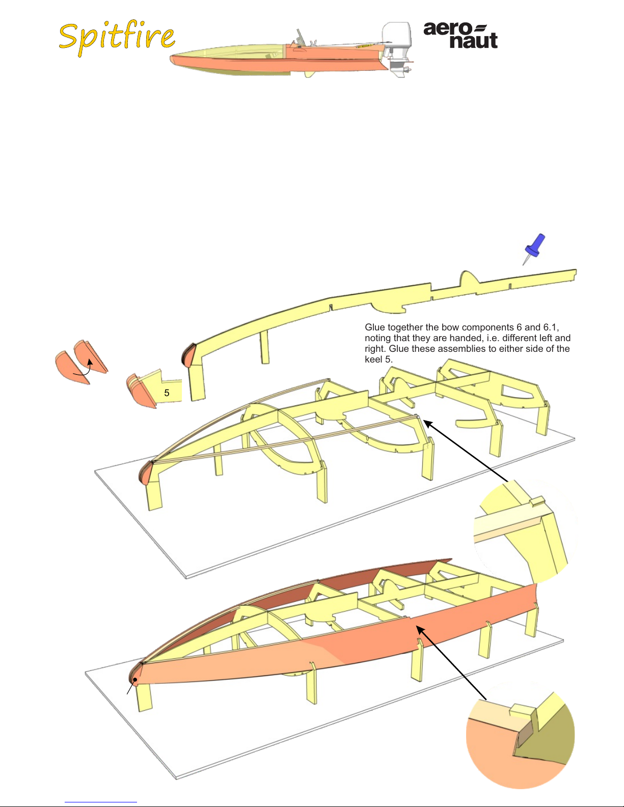
Glue together the bow components 6 and 6.1,
noting that they are handed, i.e. different left and
right. Glue these assemblies to either side of the
keel 5.
8
8
7
Fit the hull sides 8 in the notches of frames 1 to
4, aligning them with the step in frame 3 - as
shown in the detail view - before gluing them to
the stepped shoulder of parts 6.1. Glue the hull
sides 8 to the frames and the stringers 7.
3
6.1
5
Power system:
Aqua Race 60 outboard motor Order No. 7005/01
without electric motor and propeller
28 mm Ø outrunner motor / 3.17 mm shaft / 3000 KV
Two-blade boat propeller, 29 - 31 mm Ø
actronic 40 speed controller Order No. 7002/51
Prog-Card for actronic 40 Order No. 7002/49
2 x 2S 1800 mAh LiPo or 7 NiMH cells
1
2
3
4
5
0
7
7
7
3
Insert frames 1 to 4
in the slots in the
Depron jig 0. Insert
the keel 5 in the
notches in the
frames and the jig 0,
and glue the parts
together. Allow the
glue to set hard, then
glue the stringers 7
in place as shown.
Order Number
1
2
3
3052/00
3
Gluing the internal part 4.1 of frame 4 to the structure
produces a buoyancy chamber in the bow which
renders the boat unsinkable.
Tip
9
11
8
11
8
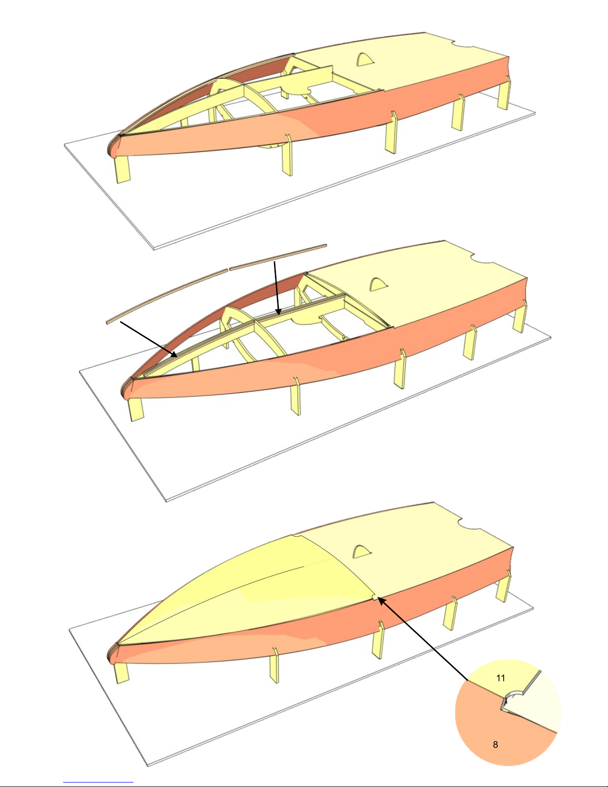
Glue the aft bottom panel 9 to
frames 1 to 3.
1
2
3
Glue the half-frame 10 to the bottom
panel 9, flush with frame 3 and the
step in the hull sides 8.
Glue the reinforcements 5.1 + 5.2 to
both sides of the keel 5.
Glue the forward bottom panel 11
to frame 10, aligning it with the
step in the hull sides 8, then glue it
to the stringers 7.
10
9
3
8
5.1
5.2
5
4
5
6
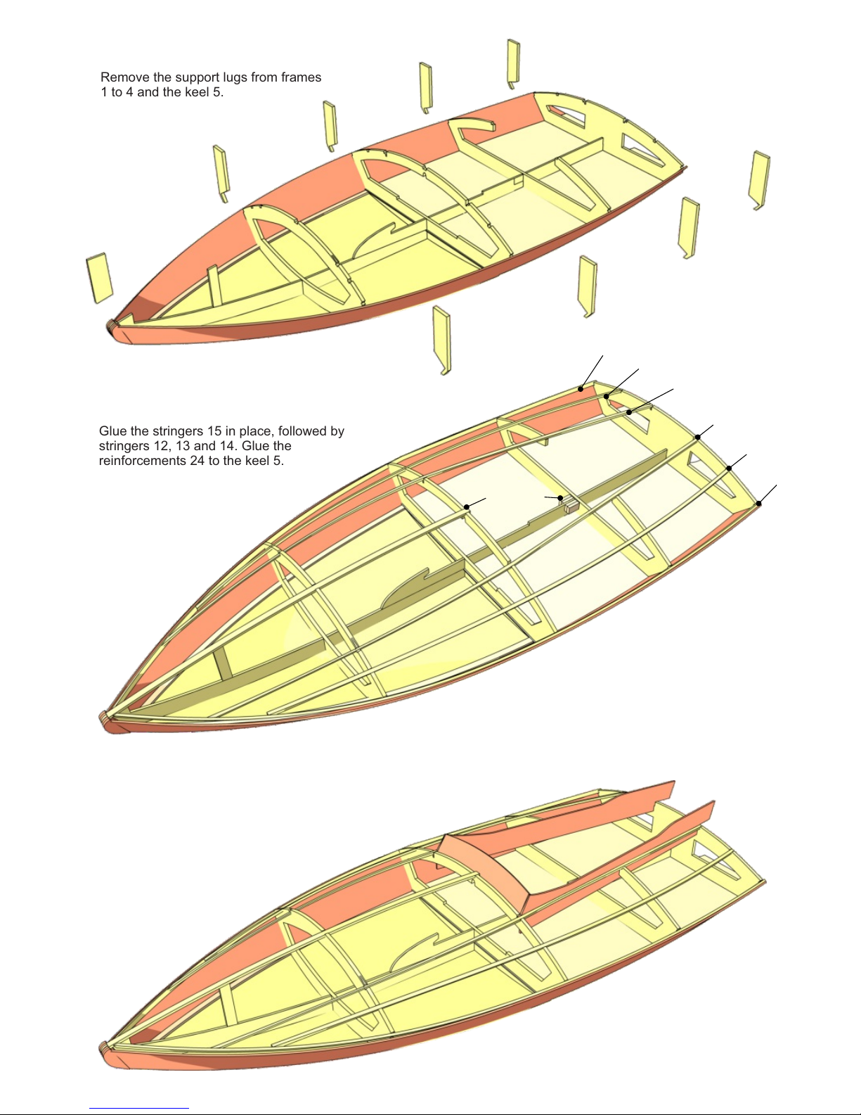
Remove the support lugs from frames
1 to 4 and the keel 5.
5
1
2
3
4
1
2
3
4
Glue the stringers 15 in place, followed by
stringers 12, 13 and 14. Glue the
reinforcements 24 to the keel 5.
16
16
17
Glue the cockpit sides 16 and
the cockpit front panel 17 in
place.
12
13
14
14
13
12
15
24
5
7
8
9
Apply several coats of sanding sealer or
boat lacquer to the inside of the hull to
waterproof it, but do not apply the lacquer
to the top edge of the frames and stringers.
10
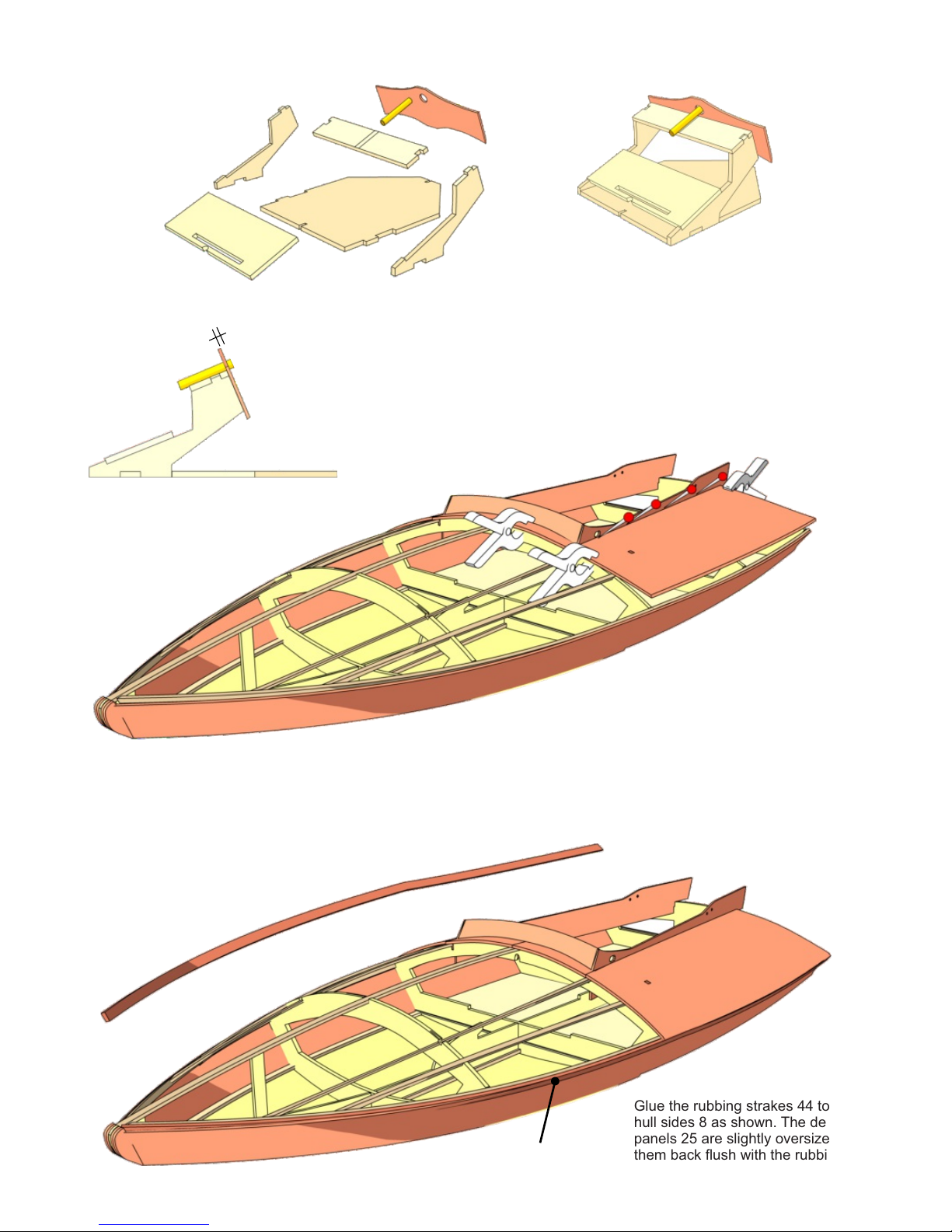
Assemble the control stand, which supports the steering
wheel and servo, from parts 18 to 23. Note that parts 18
and 19 must be at right-angles to each other. The brass
bush 22 should project out of the instrument panel 23 by 1
mm. Place the completed control stand in the hull, but do
not glue it in place; it needs to be detachable.
18
19
19
20
21
22
23
25
8
3
Glue the rubbing strakes 44 to the
hull sides 8 as shown. The deck
panels 25 are slightly oversize; sand
them back flush with the rubbing
strakes when the glue has set hard.
44
44
25
11
12
13
The right and left aft deck panels 25 can now be glued
to the frames and stringers: start by gluing them only to
the area bounded by the stringers 13 and 14, and
secure the panels with spring clips and pins as shown.
Allow the glue to dry out for at least twelve hours, as
the next stage places the glued joints under stress.
Now glue the aft deck panels 25 to the frames and the
hull sides 8, securing them with strips of adhesive tape.
23
22
1 mm
 Loading...