

Page 1
User Guide
Version 1.0.22
1
Page 2

CONTENTS
1. Safety
2. Introduction
3. Installation
4. Wiring
5. Configuration
6. First flight
7. Problems and solutions
8. Thanks
2
Page 3

1. SAFETY
R/C models such as helicopters are not toys! It is necessary to check all
instructions of the manufacturer of the model, comply with local laws, carry
out preventive checking of the model and repair all deficiencies
immediately.
Rotor blades and propellers rotate at high speed and, if used incorrectly,
can lead to serious injury to persons or damage to the model.
If you encounter any problems, contact your model shop or experienced
modelers.
Especially, pay attention to your own safety and the safety of others. Never
fly among humans, or animals, or on private property without authorized
access.
Fly only in safe places where no additional damage is possible to other
objects, because the model can become unmanageable for various
reasons, such as failure of electronics or wear parts, pilot error or
interference.
Do not try to control crashed models nor repair the damaged parts, replace
them with new ones.
Never fly the model with vibrations, it may be even uncontrollable. Also,
flight characteristics can be much worse. Find the source of the vibrations
and fix the problem.
Spirit is not an autopilot, it is necessary to have knowledge of flying R/C
models. The system is only designed to improve flight performance.
We recommend using R/C simulators designed for training before the first
flight.
User takes full responsibility for any damage or injury, because the
manufacturer is not able to guarantee correct conditions in which the unit is
being used.
3
Page 4

2. INTRODUCTION
Spirit is a device for stabilizing R/C models such as flybarless helicopters,
which features an electronic paddle simulation and a rudder gyro.
Thanks to flybarless mechanics, the system improves the efficiency and
maneuverability of the helicopter, while also extending flight time.
Flight characteristics are easily customizable according to your preference
from stable flight for beginners to demanding acrobatics with maximum
agility for experts.
Because the Spirit uses the most advanced technology, the model can be
controlled very precisely even under harsh conditions such as strong wind
while maintaining a constant pirouette.
This user guide will help you to properly mount the unit on a model and carry
out configurations step by step to prepare it for the first flight. It is very
important to carefully adjust everything to make your flight as pleasant as
possible.
Please check our website spirit-system.com for downloading new firmware
and software updates.
You can also raise your questions in our forum.
4
Page 5
3. INSTALLATION
The mounting of Spirit plays an important role for the correct operation of
your model.
Find a suitable location where vibration is as low as possible - that location is
usually given by the manufacturer for mounting the gyro.
A very significant factor is that the unit should be positioned exactly
perpendicular to each rotational axis.
The unit can be mounted in two different positions. Depending on your
preferences it can be:
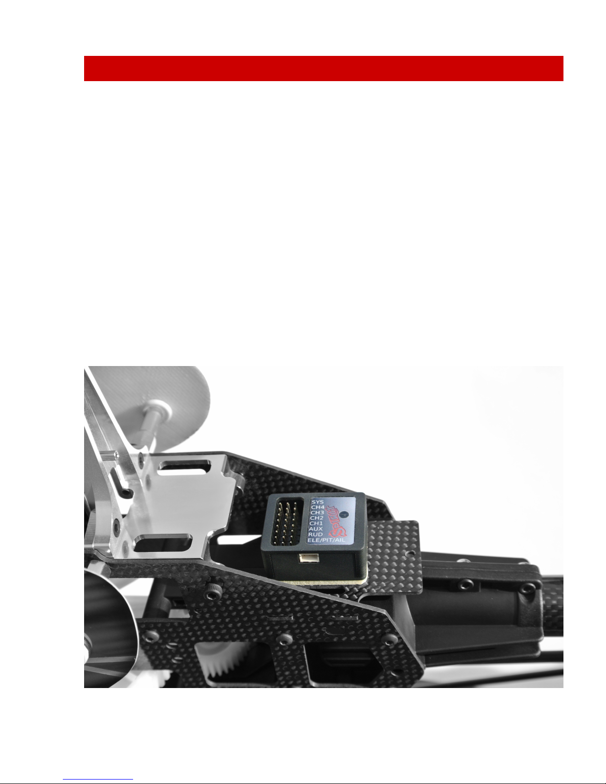
Horizontal
The unit is attached to its lower part so the connectors face upwards. It can
be rotated by 180° in yaw axis so that the connectors can be closer to the
front or rear of the model.
The unit is always positioned parallel to the longitudinal axis of the model.
5
Page 6
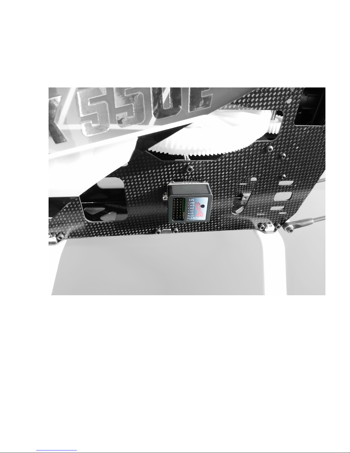
Vertical
The unit is located on the side so the connectors are also at one of the sides.
It can be rotated by 180° in yaw axis so that the connectors can be closer to
the front or rear of the model.
The unit is always parallel to the longitudinal axis of the model.
In order to better avoid vibrations on the model, it is necessary to choose the
right double-sided tape. It should prevent the transmission of vibrations from
the model, which are undesirable for the unit.
Vibrations may be not only created by incorrectly balanced blades or
propellers, but also by damaged bearings, bent shafts and other
mechanical issues.
6
Page 7

4. WIRING
Wiring to the unit depends on the type of used receiver.
Spirit can be connected as a standalone tail gyro or flybarless system.
WARNING
Spirit is pre-programmed to 1520us servo neutral impulse and 50 Hz
frequency – get servo parameters from the manufacturer.
If the neutral impulse is different such as 760us, do not connect this servo yet,
it could be destroyed!
Some connectors have non-standard dimensions. They could interfere with
neighboring positions after plugging in the unit. As a solution, we
recommend to replace it for JR or Futaba connector.
Never plug a connector for powering the unit to SYS or ELE/PIT/AIL positions!
4.1. STANDALONE GYRO
Owners of a flybared helicopter can take advantage of the head-lock gyro,
which keeps the tail in the direction given by the transmitter irrespective of
effects from wind or any unwanted forces.
It is required to connect rudder servo into position CH4 of Spirit unit.
In case you use a standard receiver, you will need to connect GEAR (or AUX)
from receiver with AUX position on the unit.
Secondly, connect cable from receiver position RUD to position RUD on the
unit.
4.2. FLYBARLESS
Owners of a flybarless helicopter can take advantage of the head-lock gyro
and also cyclic stabilization. This will stabilize the model in all axes; moreover,
it should be less prone to wind, extend flight time and make the model more
agile.
Flight characteristics should be more pleasant which allows the pilot to carry
out even the most challenging maneuvers.
7
Page 8
Rotor blades are directly linked to the cyclic servos, so demands for servos
are significantly higher. They should be faster and stronger to respond as
quickly as possible to any change.
Even flybarless rotor blades are different in some aspects. For better flight
characteristics it is recommended to use them.
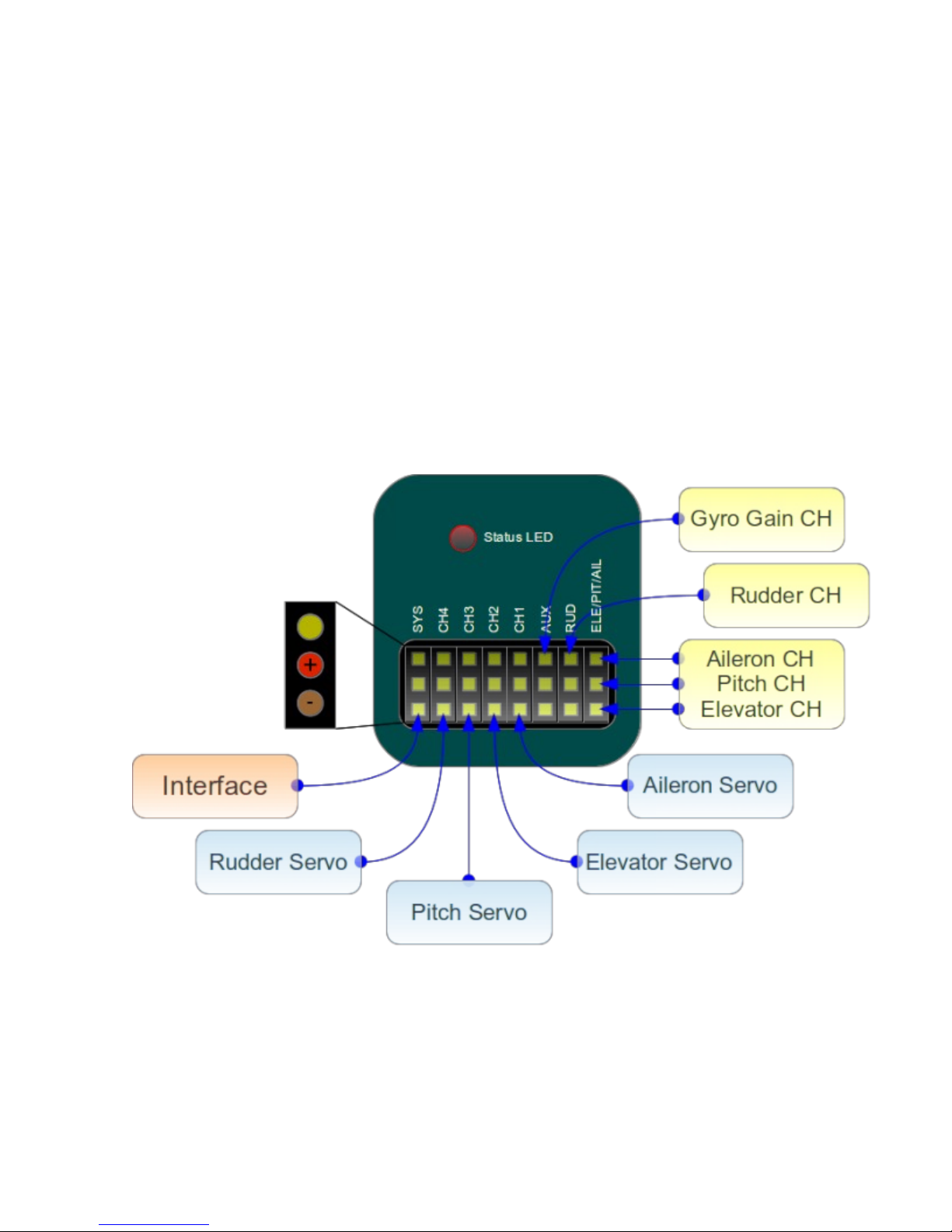
In case you intend to use Spirit as flybarless system all servos should be
connected in the corresponding positions:
CH1 (aileron), CH2 (elevator), CH3 (aileron/pitch), CH4 (rudder).
For standard receivers it is necessary to use two normal and one special
cable. Three connectors should be plugged into the receiver and the end of
this cable to the unit.
4.3. CONNECTION OF STANDARD RECEIVER (PWM)
The unit is powered by two cables from the receiver connected to AUX and
RUD positions.
Never plug a connector for powering the unit to SYS or ELE/PIT/AIL positions!
8
Page 9
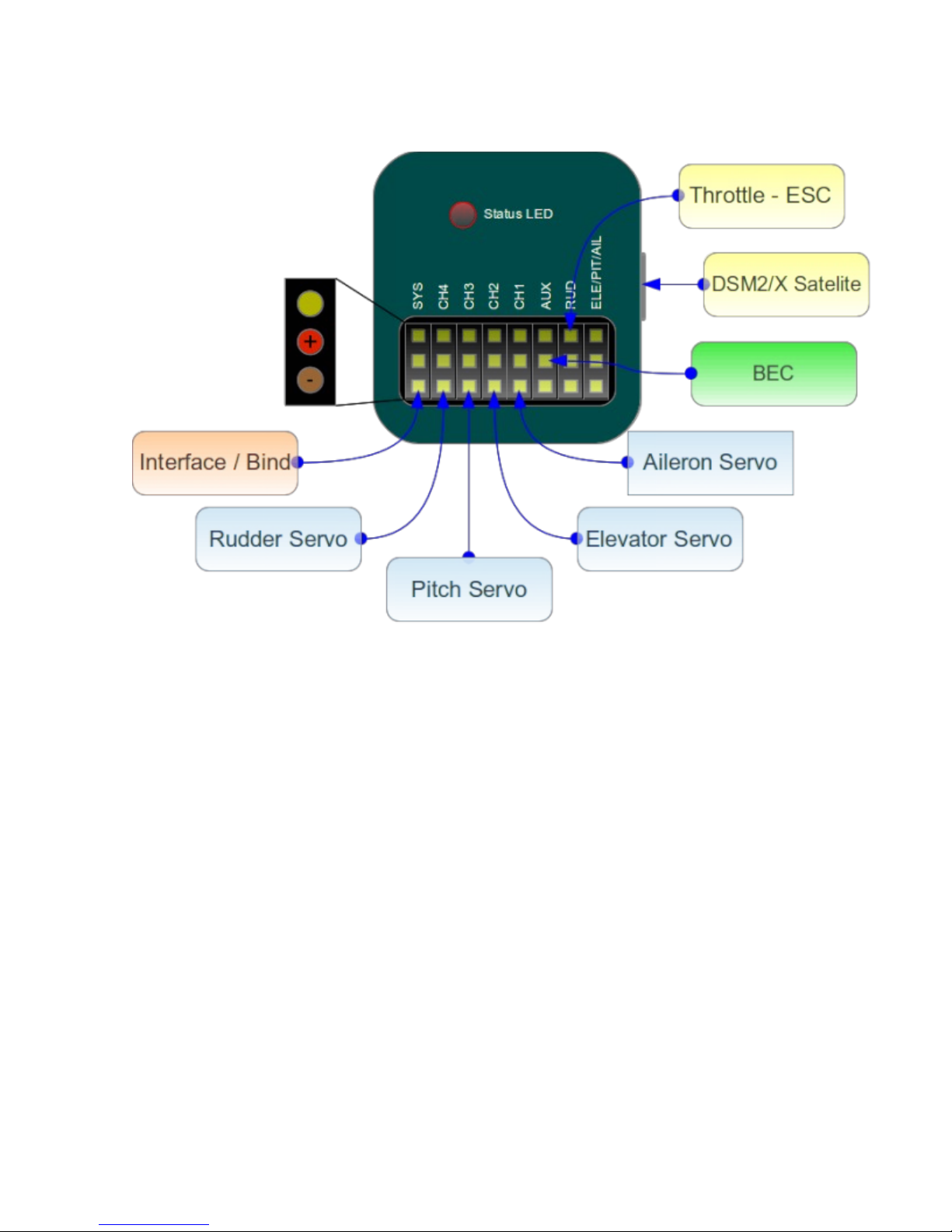
4.4. CONNECTION OF SPEKTRUM DSM2/X SATELLITE
Connection to BEC is optional. In case that the model is powered by an
external power supply (other than internal BEC) BEC must be connected to
AUX position.
Never plug a connector for powering the unit to SYS or ELE/PIT/AIL positions!
9
Page 10
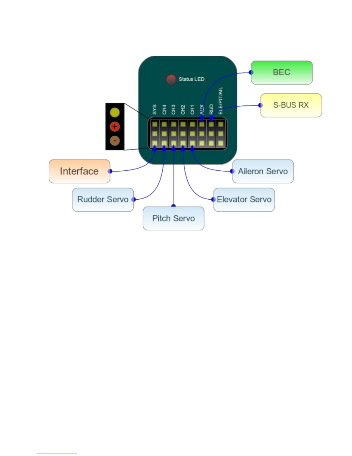
4.5. CONNECTION OF FUTABA S-BUS RECEIVER
WARNING
When using S-BUS it is necessary to have an INVERTER which can be
purchased separately. Inverter replaces cable between receiver and unit in
RUD position.
Connection to BEC is optional. For models of class 500 and larger it is
recommended to use dual power supply cables due to increased power
consumption. That means besides the inverter, additional power supply
cable should be connected to AUX position.
Never plug a connector for powering the unit to SYS or ELE/PIT/AIL positions!
4.6. UNIT
All cables connected to the unit must be oriented so that the signal wire
(orange) is closer to the connector pin labels, respectively to center of the
unit.
10
Page 11

5. CONFIGURATION
Configuration is one of the next important steps for correct operation of the
system.
Configuration is performed using the software, which combines efficiency
and simplicity, while offering a set of adjustable parameters, including
advanced options.
5.1. CONNECTION WITH PC
Before you begin the actual configuration it is necessary to connect the
system to a computer.
This connection allows so-called USB interface comprising a serial converter
and interface cable.
Depending on the operating system a driver must be installed after
connecting the converter to USB port.
In case a driver is installed successfully a new virtual COM port should be
visible in the software and device manager.
MS WINDOWS
Install a driver from software installer. This process will be described in
following section.
APPLE MAC OS X
Download and install a driver from following URL:
http://spirit-system.com/dl/driver/SiLabsUSBDriverDisk.dmg
GNU/LINUX
Nothing has to be installed.
11
Page 12

5.2. CONNECTION WITH UNIT
If you already have attached a USB interface to your computer, it is
necessary to also connect the interface cable to SYS position in Spirit.
To establish a connection, connect a battery to the model first. To power the
unit a BEC, battery, or receiver's power supply can be used.
Mostly RUD and AUX connector pins are used to power the unit.
The middle wire must be positive voltage potential of the voltage supply, socalled Plus (3 – 15V voltage range supported).
WARNING
If the unit is not configured yet (e.g. new unit) it is advised to not connect a
servo.
5.3. CONFIGURATION SOFTWARE INSTALLATION
Software is capable of running on MS Windows, Apple Mac OS X, GNU/Linux
and Android platforms. If it is not installed yet, you can download it from the
Spirit web site:
spirit-system .com .
Please download software for your platform, then you should proceed with
following guidelines.
MS WINDOWS
Start the downloaded software – installer and go through wizard.
If the driver is not installed yet, please select it in installer to be installed.
Installer should go through all necessary steps to state that your computer is
prepared for the first start of the configuration software. Configuration
software can be launched from your desktop or program list, called „Spirit
Settings”.
APPLE MAC OS X
Install the downloaded software with opening DMG file. Then move the content to
Applications. Configuration software can be launched from Applications menu
with „settings“.
GNU/LINUX
Extract all files from downloaded archive to, for example, home directory.
Configuration software can be launched from the newly created directory
with file „settings.sh“.
12
Page 13

5.4. CONFIGURATION SOFTWARE START
If the previous guidelines are met and unit is turned on and initialized (LED
lights), you can start the software on your computer.
Please start the software; you can do so from e.g. desktop or directory
where it was installed.
WARNING
Configuration software should be started after unit initialization process!
Whenever it is connected and the unit is initialized (status LED is on) you can
perform any settings.
Configuration during flight is forbidden for safety reasons.
PROBLEMS WITH WINDOWS 7/8
In case configuration software is not able to detect valid COM port, start the
software as administrator.
13
Page 14
5.5. SOFTWARE USAGE
After successful connection with the unit, all possibilities should be
accessible, otherwise try to either choose another communication port
(Device) or try to restart the software, disconnect the unit from the power
supply and repeat the procedure. Make sure the software is launched after
initialization is done.
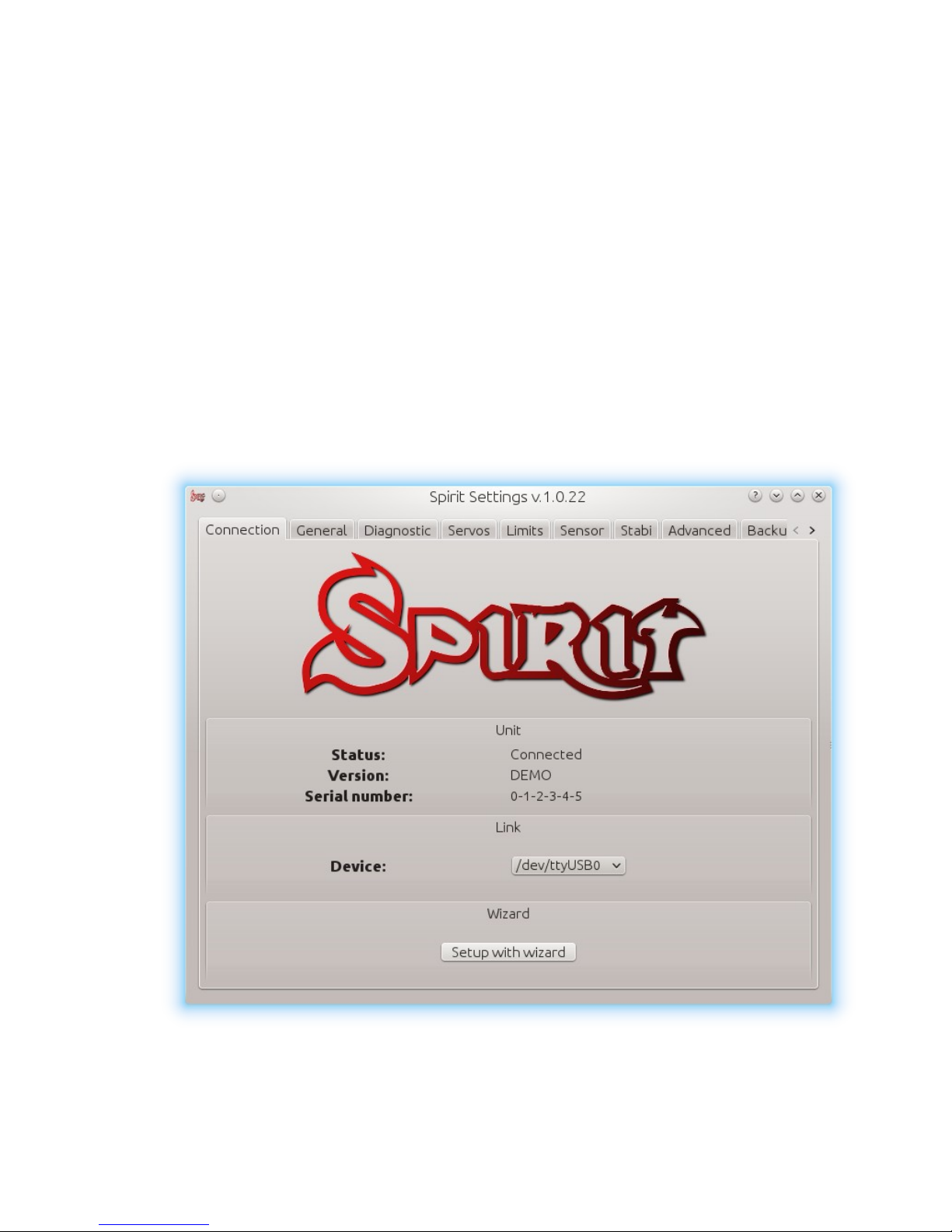
5.5.1 CONNECTION TAB
This tab indicates the current status of connection, informs about the current
version of the firmware, displays the serial number of the unit and allows you
to change communication port. In addition it features a wizard for a first
setup.
We recommend using this wizard, as it guides you through a basic setup in
the easiest way.
14
Page 15
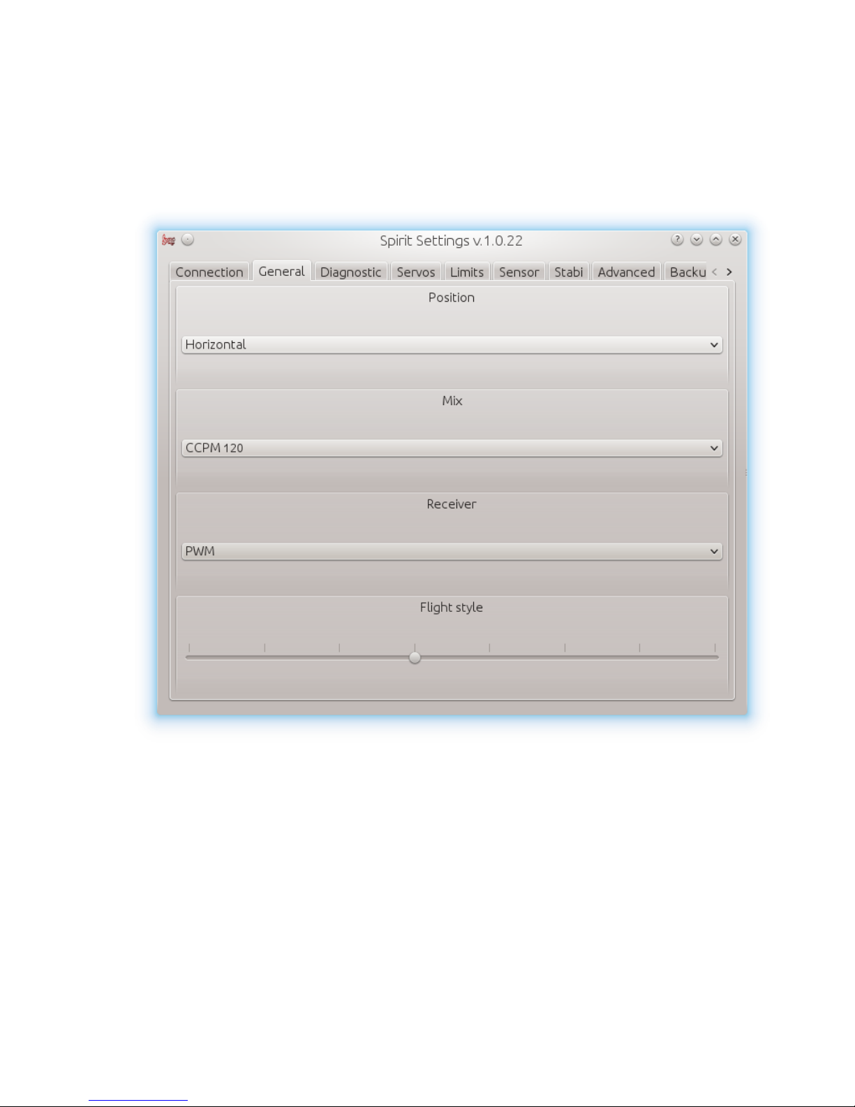
5.5.2. GENERAL
In case you have already set up the unit using the wizard, you can make
additional adjustments. All values here are the same as the ones you have
selected in the wizard and vice versa.
WARNING
Whenever parameters are changed, new value is immediately applied.
Unless settings are saved, after disconnecting the power supply all unsaved
changes are lost, see Backup tab.
15
Page 16

Position
Select a position in which the unit is attached to the model.
See section 3. Installation.
Mix
Select a swash type mixing of your model. In most cases it is CCPM 120°.
Mixing in the transmitter must be turned off. It is necessary to set H1 type.
Receiver
Select the type of receiver you want to use:
PWM – standard receiver.
PPM - single line connection.
Spektrum DSM2/DSMX - DSM2/DSMX satellite.
Futaba S-BUS - receiver connected via S-BUS.
Flight style
Sets how the model will behave in flight.
This parameter is used to control and adapt behavior according to the
requirements of the pilot.
Lower value means that the model will behave more consistently, more
controlled by the unit.
Higher value means more natural behavioral. The response of stick
movements are more flybar-like.
This parameter does not affect how the model will be stable.
Most pilots prefer default value - 4.
16
Page 17
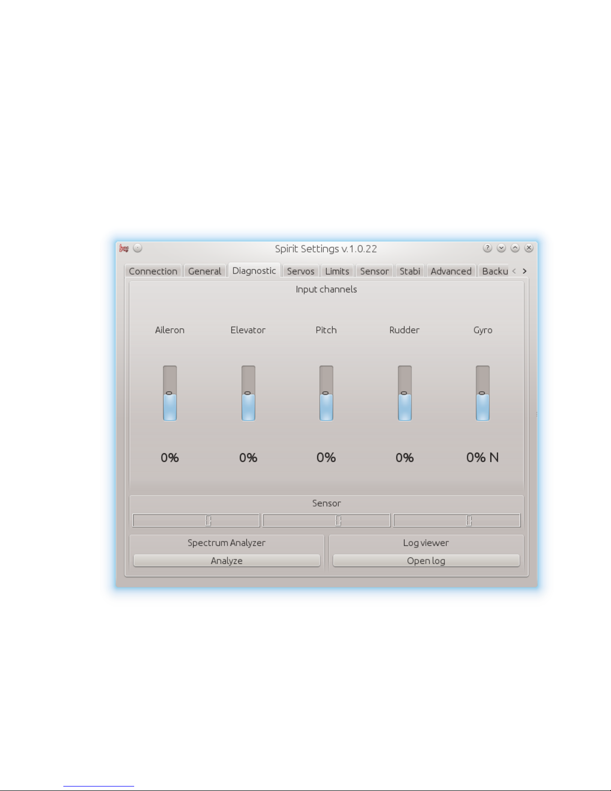
5.5.3 DIAGNOSTIC TAB
If the settings in the previous tab are done it is recommended to do
adjustments in the transmitter at this time.
Each transmitter is different and the center of the channel impulse is never
exactly the same. Even with increasing wear or due to environmental
influences, center of channels can move slightly.
Another factor is the maximum and minimum value of each channel.
Also, there may be greater deviations. Therefore, this software displays these
values. So basically you can unify all transmitters to fulfill requirements.
WARNING
For proper operation of the unit, it is necessary to check values of aileron,
elevator and rudder channels. These three channels must be in neutral stick
deflections at approximately 0%!
17
Page 18

The unit automatically detects the neutral position during each initialization.
Do not ever use subtrim and trim functions on your transmitter for these three
channels, otherwise it will be considered as a command to move.
So make sure all subtrims and trims are zeroed.
It is also recommended to set the maximum and minimum values.
Test the minimum and maximum deviation for all channels.
If these values are not equal to -100% respectively 100% in the diagnostic tab
it is necessary to compensate this difference.
You will need to set this with dual rate or travel adjust function for both
directions.
Besides channels such as aileron, elevator and rudder, it is necessary to
check pitch channel, too. For this channel it is allowed to use subtrim
function to achieve the center value as precisely as possible
When collective pitch curve is in range between -100 and 100%, the middle
of the stick should be equal to 0%.
After these settings, everything should be configured with regards to the
transmitter.
But if some channel oscillates around the center too much, it may mean
wear of the transmitter, respectively potentiometers. This can be
compensated by increasing stick deadband, described later in Advanced
tab.
If you see that values in channel aileron, elevator, or rudder are marked in
bold, it is recognized as a command to move/rotate the axis.
18
Page 19
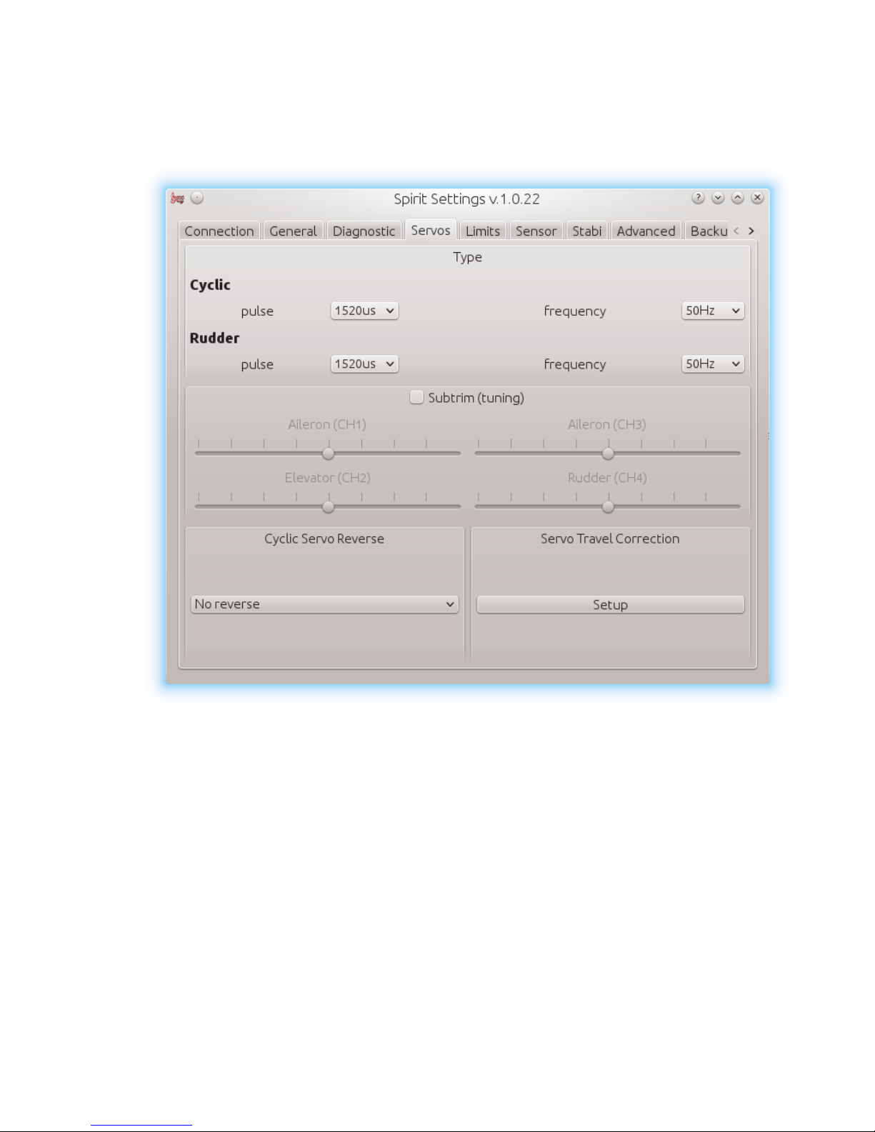
5.5.4 SERVOS TAB
This tab is used for servo configuration, you should be especially careful here.
Type
In this section, set values according to servo specifications for neutral pulse
and frequency.
For analog servo frequency is usually max. 60Hz.
Subtrim (tuning)
Ideally, without rotor head, use cyclic leveler to align servo horns so the
swashplate will be in horizontal position as accurately as possible,
respectively perpendicular to main shaft while servo horns are
perpendicular, too.
19
Page 20

This is done by ticking item Subtrim (tuning). Then the unit should be switched
into a special mode where the collective position should be neutral all the
time. In addition, stabilization will be turned off.
Servos can be easily adjusted at this time. When all is completed, a
swashplate should be exactly perpendicular to the main shaft and in
addition collective pitch must be at 0° (it is possible to measure the angle
with a pitch gauge with rotor head and blades now).
There is also requirement for servo horns – they should be perpendicular to
servo cases, too.
All servos, i.e., CH1, CH2, CH3 and CH4, are set separately on individual
sliders. CH1 and CH3 are the aileron servos. CH2 controls the elevator and
CH4 controls the rudder.
It is also recommended to set subtrim and mechanics of rudder so that servo
horn is perpendicular to its case and simultaneously rudder pitch is at 0°.
This setting will affect rudder stop performance.
If all is set up, it is necessary to untick the Subtrim (tuning) item to turn off the
special mode.
WARNING
After exiting the special mode stabilization, steering should work again.
Be sure your collective pitch channel is configured correctly in the
transmitter.
That means you should see -100% to 100% in the diagnostic tab.
Double check that 0% in diagnostic tab corresponds with neutral position of
a collective/throttle stick (with linear -100% - 100% collective pitch curve).
Cyclic servos reverse
Choose which servos should be reversed – reversed direction of motion.
While changing the collective pitch all servos should move in same direction.
It is possible to set correct direction of collective travel in the transmitter.
Without reverse - all servos without reversing
CH3 - CH3 servo reversed
CH2 - CH2 servo reversed
CH2 & CH3 – CH2 and CH3 are reversed
20
Page 21
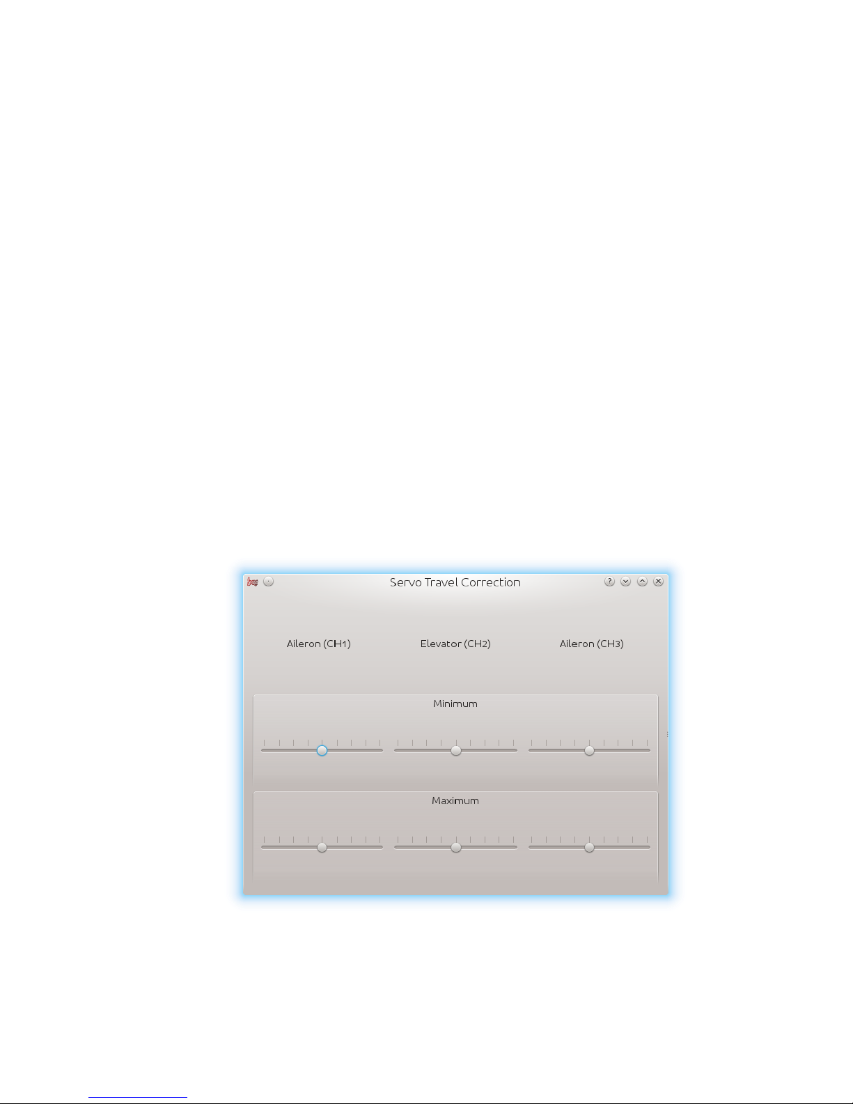
Servo travel correction
If you click the button anew, a window should appear. There, you are able
to modify and correct travel proportion for each servo individually. Some
servos are not very accurate regarding travelling in both directions.
This inaccuracy may have a negative impact on flight characteristics. If the
window is open, the unit switches to the mode for doing these corrections.
It is expected that in the previous step Subtrim (tuning) the swashplate was
set at zero collective (0° rotor blades pitch).
The procedure is such that you should use cyclic leveler to determine
whether there is a deviation on any of the servos in the lowest and highest
collective position.
For both positions, it is necessary to set the values separately – this is the
reason for 6 sliders. If the travel deviation is less than necessary, increase the
value. Otherwise, decrease.
This correction is also useful, if there is asymmetric geometry on the
helicopter. This phenomenon is observable if you cannot achieve same
collective pitch in both directions. In this case, it is necessary to modify the
minimum or maximum for three servos to the same value.
If you are unsure about your settings, it is better to leave the sliders in the
middle, position 0.
If you are unsure about your settings, it is better to leave the sliders in the
middle, position 0.
21
Page 22
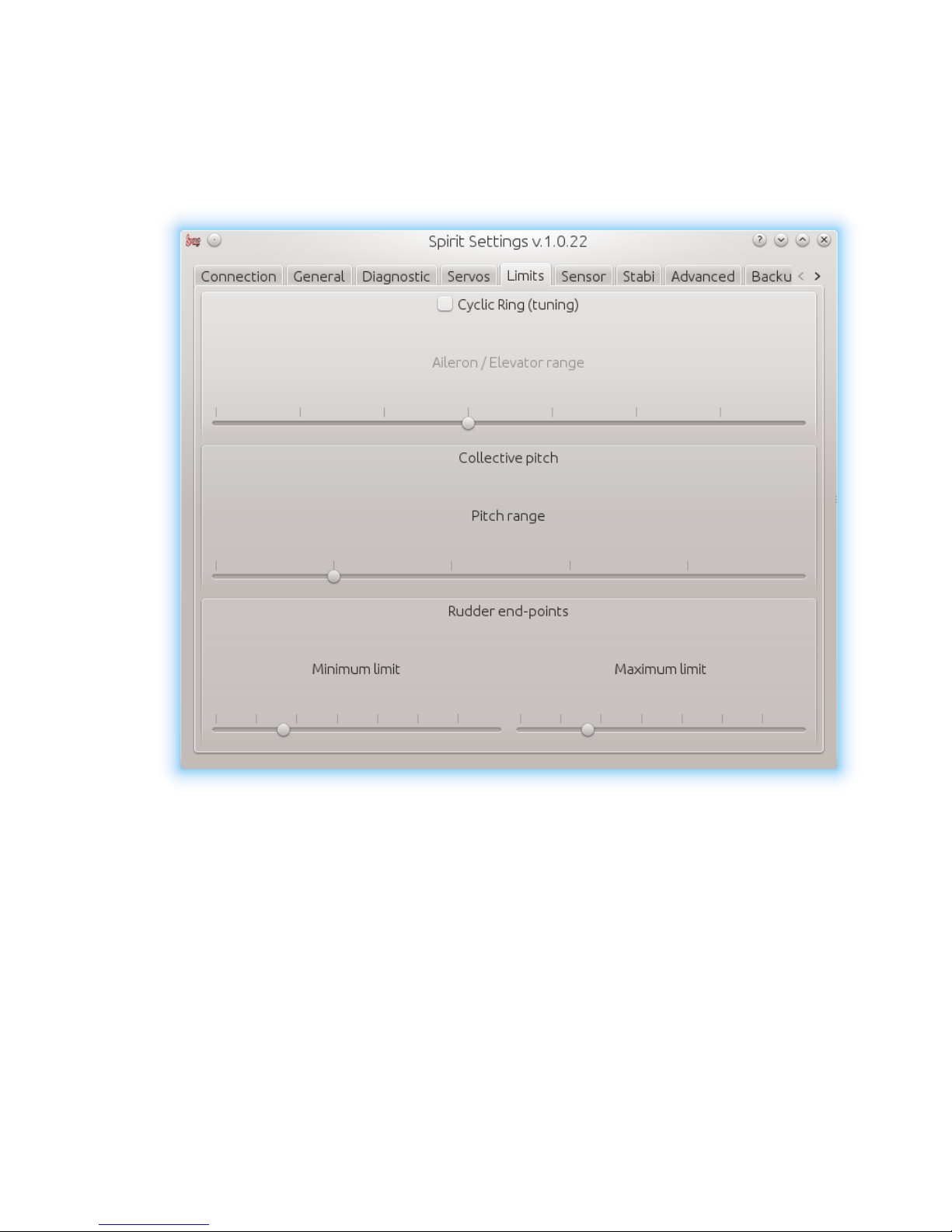
5.5.5 LIMITS TAB
This tab affects limits and servo travel ranges.
Cyclic Ring (tuning)
This parameter sets the electronic implementation of cyclic ring, which is the
function to achieve the highest deflections without mechanical binding
(binding of servo horns, pushrods, etc).
WARNING
The settings here should be done very carefully to avoid damage of the
model.
22
Page 23

First, set collective range parameter to, for example, +-12°. We recommend
using -100% to 100% linear collective pitch curve in the transmitter.
Now it is time to set Ail/Ele – max. cyclic tilt range. Try to set the largest
possible deflection. This parameter does not directly affect the speed of
rotation, but if it is too low, the model may not rotate constantly at all times.
This setting should be ideally done with 0° collective, i.e., the servo arms
should be perpendicular to main shaft. Then carefully check, with the sticks
deflections in all directions, that mechanical binding does not occur.
You should also check min. and max. collective position.
This parameter acts as a so-called electronic Cyclic Ring.
If you enlarge the travel of the collective, this parameter must, in some
cases, be adjusted.
In case the cyclic ring range is insufficient, it is possible that pitch-up can
happen during fast forward flight (even if the pitch-up compensation is on its
maximum value). This is because the model will not be able to keep up
direction with the configured range.
Rudder Limit
Min/Max - Sets the minimum and maximum deflection of rudder rotor
blades.
We recommend setting these values for both directions to the maximum
allowed range by the manufacturer of the helicopter. Otherwise, rudder
cannot be able to keep the yaw direction during demanding maneuvers.
23
Page 24
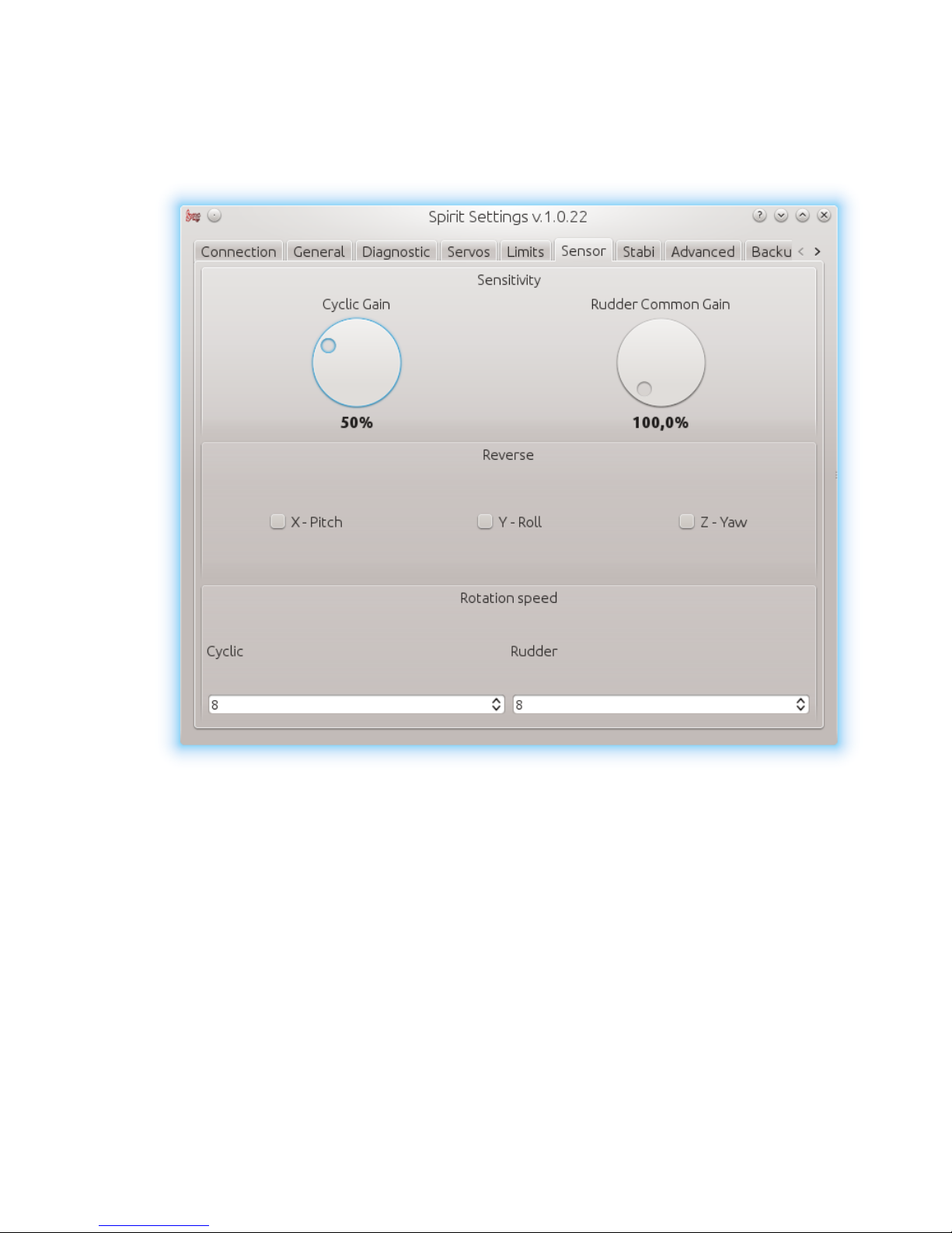
5.5.6 SENSOR TAB
This tab is the last important part of the settings which must be configured.
Sensitivity
The rotary manipulator adjusts the gyro sensitivity for aileron, elevator and
rudder axes.
Cyclic gain - the higher the value is, the higher the accuracy.
The default value is preconfigured to 50% gain.
For most models optimal value is around 60%.
Rudder Common Gain - 100% means no multiplication. Mostly, it is good
value for 550-class helicopters and smaller. For bigger helicopters it is often
higher – 130% could be fine.
24
Page 25

Reverse
Sets compensation direction for each axis separately.
Swashplate should tilt as it is copying horizon.
Rudder blades should compensate to opposite direction as you rotate with
the model.
WARNING
This parameter is the most important one, it is necessary to carefully check
the orientation of compensation and set it correctly. As a result of improper
compensation, model will be completely out of control and can cause
serious damage.
Rotation speed
The default values should favor beginners more, model should behave
slowly. This factor also depends on the mechanical linkage ratio or D/R (Dual
Rate) in the transmitter and also on Ail/Ele limit.
The larger the value, the greater the rotation speed.
8 - default
We recommend to set this parameter within range of 6 -12. Mostly, the DFC
rotor heads tend to rotate faster so start at lower values.
25
Page 26
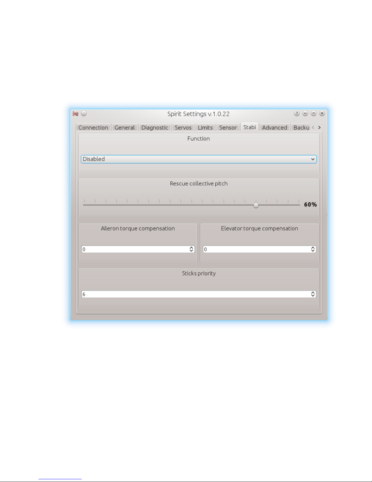
5.5.7 STABI TAB
Spirit offers you the possibility of model stabilization and rescue mode.
In the case of activation of stabilization, model should recover horizontal
position without additional corrections. This feature can greatly simplify
maneuvering and help with learning process.
Rescue mode ccomplements the normal operation of the system.
If activated, the model should recover to horizontal position and ascend
according to configuration. This function can be used any time when pilot is
disorientated or is not able to control the model in current situation.
Spirit allows you to assign a stabilization or rescue mode at the gyro gain
channel. 0 - 100% gain in the transmitter is always Head Lock-gyro mode and
with -100 – 0% gain, selected mode is activated (parameter function).
26
Page 27

This means that instead of normal (rate) mode it will stay in Head-Lock gyro
mode, plus, rescue/stabilization is activated.
So while special mode is activated gyro gain for example -70% is considered
as 70%.
This behavior can be also observed in Diagnostic tab.
WARNING
Some transmitters have a gyro range between 0 to 100% where 50% is the
middle - zero gain (e.g. Spektrum DX6i).
Function
Select function which should be activated at -100% to 0% gyro gain,
respectively. 0% - 50% gain in the transmitter.
Disabled - Normal (Rate) gyro mode
Rescue (normal) - Rescue mode recover the model to horizontal position –
skids always to ground.
Rescue (acro) - Rescue mode recover the model to horizontal position to
inverted or non-inverted state.
Stabilization – Stabilization of the model.
Rescue mode collective
Determines how quickly the model will recover to horizontal position.
100% means the maximum deflection of the blades, which was configured in
Servos tab.
It is very important to check whether the rescue mode works correctly
before the first flight (without spinning rotor), i.e., whether the direction of
collective pitch is correct. If collective pitch is not positive while helicopter is
on the ground, you have to change negative value for this parameter.
Aileron / Elevator torque compensation
If stabilization is activated and the model moves to any side in aileron /
elevator axis you can correct it with this parameter. This value may vary for
each model. You can also change the direction of compensation for both
sides.
Sticks priority
Specifies the amount of control while special function is active, i.e.; the
higher the value, the more the model will react to stick deflections.
27
Page 28
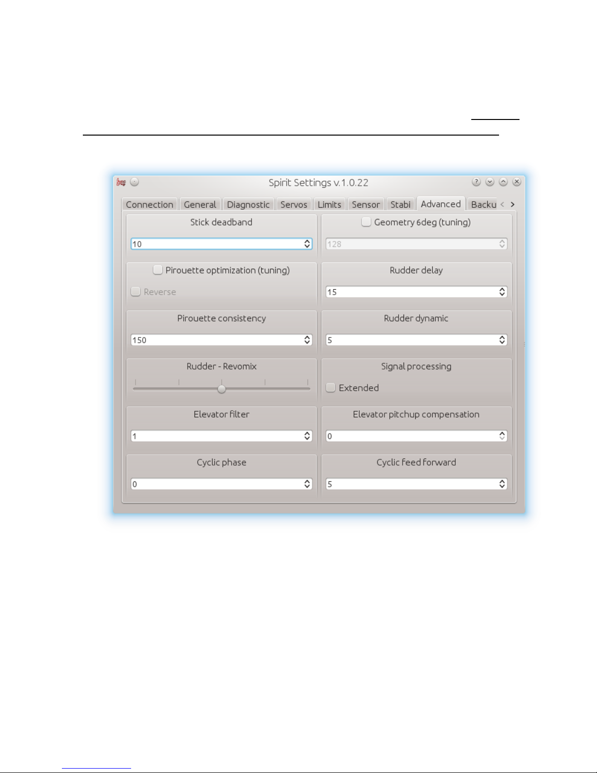
5.5.8 Advanced tab
This tab is addressed especially for advanced pilots. It is highly
recommended to understand these parameters. However, the correct
settings of pirouette optimization and geometry are necessary here, other
parameters, however, depend on the preferences of the pilot.
Stick deadband
Determines the dead area where the system does not recognize any stick
movement - depends on the preferences and transmitter accuracy.
Geometry 6deg (tuning)
For the proper operation of the unit, it is necessary to set this parameter
correctly. When enabled, unit is switched to special mode for settings of 6°
angle on the main blades. It is necessary to set the value so that the blades’
28
Page 29

angle is at 6° in aileron axis. You need to rotate your rotor head with blades
to be parallel to the longitudinal axis of the model.
A higher value increases the angle; a lower one decreases the angle.
Optimal head geometry should be in the range of about 90 – 160. If not in
this range, it is recommended to adjust the distance of a ball joint on the
servo horns or perform other mechanical adjustments.
Pirouette optimization (tuning)
If this parameter is ticked, the unit enters into a special mode in which you
should test and simultaneously set correct compensation direction.
It is possible to determine correct direction, if you rotate the model around
the yaw axis in the same manner as if you were doing stationary pirouettes.
The swashplate should stay tilted in this mode, in this case, it should behave
as a compass. That means, the swashplate should be tilted at all times to
one direction with respect to ground even when you rotate with the
helicopter.
If this is not the case, it is the wrong direction. You have to reverse it with this
parameter. If this is not correctly configured, your model cannot do
stationary pirouettes without additional movements.
When settings are completed, you can easily untick this parameter to
disable the special mode.
Tail delay
This is a parameter to smooth rudder movements. It also helps to stabilize the
rudder – it is a kind of dampening. It can handle even the smallest
movements when value is higher. The faster the servo is, the lower the tail
delay should be. For analog servos it is recommended to set value around
25. For usual digital servos it is mostly between 15 – 20. For very fast servos
(~0.04s/60°) the value is 5. If the value is too high, rudder could start to
oscillate fast and could be shaky or can cause slow rudder stop.
Pirouette consistency
This parameter determines the consistency of pirouettes and holding
performance – fast recovery of correct angle. If pirouettes are not so
constant, i.e., pirouette speed is changing during some maneuvers, it is
necessary to increase this parameter.
29
Page 30

The value is individual for every model. It depends on many factors of your
rudder mechanics, head speed, etc. Before settings of this parameter are
performed it is recommended to set the gyro gain first.
If the value is too high, the rudder can oscillate in a bigger range. It can
cause even bad stopping performance. The value should be between 150
and 175.
Rudder dynamic
If the rudder does not stop correctly, for example with overshoot, this
behavior can be changed with this parameter.
5 – default value
The larger the value, the more aggressive behavior of the tail.
In case the rotor will overshoot, the value is too high.
This parameter affects, among others, response speed of the stick
movement - higher value means a faster response.
If you cannot reach symmetric stop on both sides you will need to set center
of the tail to 0° angle.
Rudder - Revomix
Revomix improves tail response, mainly to aggressive changes in collective
pitch, when you need more power to hold. Revomix is operating
dependently on the collective pitch curve in the transmitter.
By default it is turned off, because the user must set the proper portion and
direction of the pre-compensation.
The correct direction is such that the rudder blades at full positive or
negative position are moved to make force in same direction as the main
rotor - in most cases clockwise. At 0% of the collective pitch, blades should
be at 0° angle.
Allowed values: -10 to 10, default 0 – disabled; in most cases it is not
necessary to use this parameter. Mostly, rudder without mechanical issues is
able to perform very well without revomix.
Cyclic phase
The value indicates the angle by which swashplate is virtually rotated.
For example, value 90 will swap the elevator to aileron and vice versa. This
feature is recommended for models with multi-blade rotor head. For the
most models, we recommend zero value.
30
Page 31

Elevator filter
This parameter compensates the elevator bouncing while aggressive
movements are performed. The larger the value, the less compensation.
A too large value can lead to smooth elevator movement.
We recommend setting default value first. Default is 0.
Pitch-up compensation
In case steering in fast forward flight is inaccurate, i.e., small movement
reacts too rapidly or model pitches up during fast forward, we recommend
to increase this parameter gradually until the phenomenon disappears.
If the helicopter pitches up abruptly, this could be caused by too low cyclic
tilt range and high collective pitch.
In this case, you will need to increase Ail/Ele range as high as the model can
handle without any binding. If that does not help, try to increase this
parameter too.
31
Page 32
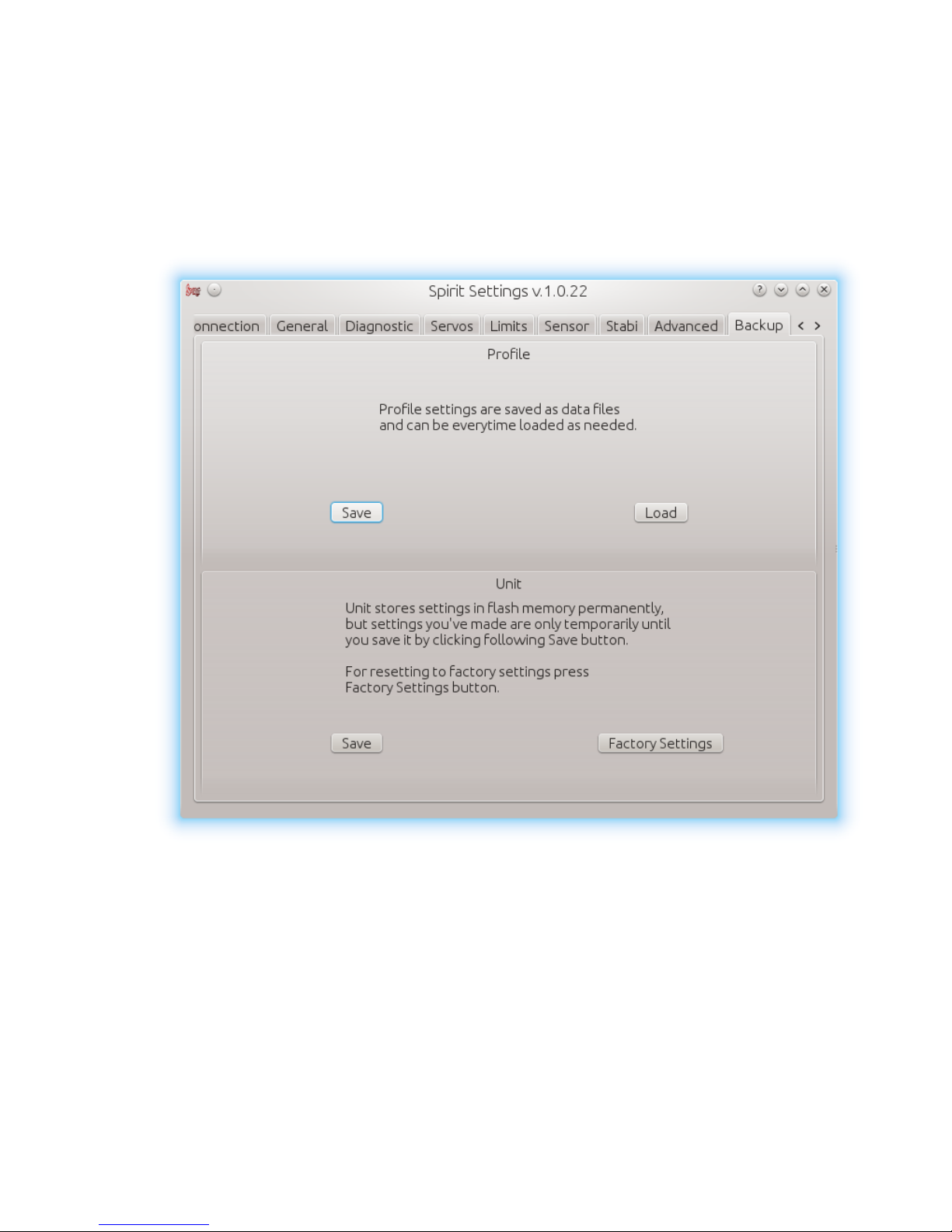
5.5.9 BACKUP TAB
You must enter here whenever you want to store the settings permanently to
the unit, i.e., settings remain stored even after the power is disconnected.
You can also save the settings to your computer here, but also, there is the
possibility to load these settings back to the unit at any time.
Profile
This section allows you to Save and Load complete settings of the unit to
specified file.
If you have more models, it is not necessary to carry out the settings again,
but just load stored settings easily with Load button.
32
Page 33

Unit
Any changes to the configuration can be saved at any time in the internal
flash memory of the unit.
To put all settings to a factory defaults, click Factory Settings.
WARNING
Remember to save the settings each time you want to store the settings
permanently. You must press Save button, otherwise the changes will be lost
after the power is turned off!
33
Page 34
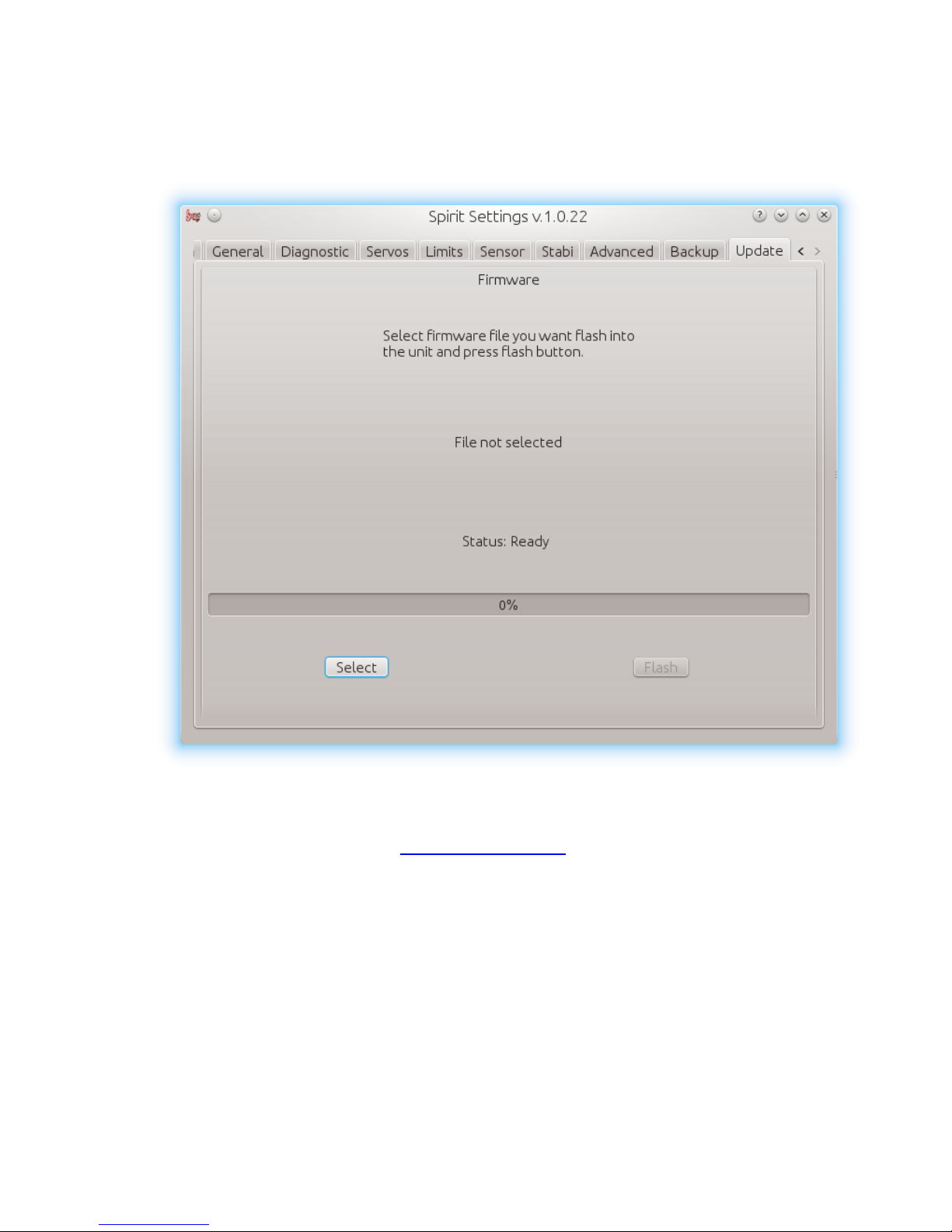
5.5.10 UPDATE TAB
If you want to change the firmware version you can do so in this tab.
Firmware
First select data file containing the firmware (*. bin) – Select button.
You can get firmware from spirit-system.com.
Once you select a file, press Flash.
The upgrade progress will be displayed here. After completion, confirmation
dialog box should indicate a successful update.
Then, unplug the unit from a power source.
Next time it will start with newly flashed firmware.
Configuration of the unit is untouched, so you do not need to save/load it.
34
Page 35

6. FIRST FLIGHT
If you are sure that the unit is correctly configured, you are ready for first
flight.
6.1. Pre-flight control
1. Turn on the transmitter and connect the battery to the model.
2. Wait for the initialization – swashplate jumps.
3. Tilt the model, i.e., tail boom up. Swashplate should compensate for
this movement and tilt in the opposite direction - keep the horizon.
4. Similarly, tilt it sideways, even in that position swashplate should
maintain the horizon.
5. Move the tail boom to any direction, tail slider/rudder blades should go
to the opposite side.
6. Check that the sticks of the transmitter react properly - correct
direction.
7. Place the model on a flat surface, and align the swashplate to run in
the event that it is not. Tail slider should be approximately in the
center of its travel range.
WARNING
If you've encountered a problem at some point, do not try to take off!
6.2. TAKEOFF
1. Spin main rotor to the desired speed - we recommend to start with
slightly lower RPM.
2. Slowly increase the collective pitch from neutral value.
3. Try to steer the rudder and check whether it has sufficient gain and
stop performance is good.
4. If control is not very precise, slowly add cyclic and rudder gain as
needed.
35
Page 36

7. PROBLEMS AND SOLUTIONS
Problem description Solution
Swashplate or tail rotor drifts after
initialization
Steering is not precise Increase cyclic gain and/or increase
Aggressive cyclic pitch movement
leads to rapid tail oscillation in a large
angular range
Model oscillates in elevator or aileron
axis
Tail oscillates rapidly Decrease gyro gain in the transmitter.
Model pirouette rotation is too slow/fast Increase/decrease rotation speed for
Servos jitters randomly without external
influences
Check trims and subtrims. Sticks neutral
position must be 0%, see the Diagnostics
tab. Increase Stick deadband in
Advanced tab.
the gyro gain in the transmitter.
Add exponentials in the transmitter.
Decrease pirouette consistency in
Advanced tab gradually by 10 until the
phenomenon disappears. Check the tail
mechanics, it is necessary that
everything runs smoothly.
Decrease cyclic gain in Sensor tab.
rudder in Sensor tab.
Check the cable connection between
the receiver and the unit.
During stationary pirouettes model drifts Check the correct direction of pirouette
optimization in Advanced tab.
Agressive elevator stick movement
leads to bouncing
Cyclic steering is delayed Increase cyclic feed forward in
Increase elevator filter in Advanced tab.
If the result is unsatisfactory, decrease
cyclic feed forward in Advanced tab.
Advanced tab.
36
Page 37

8. THANKS
To all who in any way participated and are participating in the development
of Spirit, many thanks!
Special thanks to:
Adam Kruchina
Daniel Beneš
Dušan Habada
Elke Lalanza
Jens Lalanza
Martin Přinda
Martin Štvrtňa
Milan Křivda
Milan Pěchovič
Petr Čada
Petr Koťátko
René Štefánik
37
Page 38

Declaration about conformity
It is hereby confirmed that Spirit unit is being produced according to EMC
directive 2004/108/EC, electromagnetic compatibility.
Tomáš Jędrzejek © Spirit System
38
 Loading...