

Spirit Fitness CE900ENT Owner's Manual

CE900ENT ELLIPTICAL TRAINER
OWNER’S MANUAL

Spirit Fitness

www.spirittness.com
TABLE OF CONTENTS
3 IMPORTANT SAFETY INSTRUCTIONS
3 IMPORTANT ELECTRICAL INSTRUCTIONS
4 IMPORTANT OPERATION INSTRUCTIONS
5 PRODUCT REGISTRATION
6 CE900ENT ASSEMBLY INSTRUCTIONS
11 CONSOLE OPERATION
20 TOUCH SCREEN OPERATION
27 PROGRAMMING THE CONSOLE
34 GENERAL MAINTENANCE
35 MANUFACTURER’S LIMITED WARRANTY
Thank you for purchasing our product, please save these instructions. Please do not perform or attempt any
customizing, adjustments, repair or maintenance that is not described in this manual.

2
Spirit Fitness
Congratulations on your new elliptical trainer and welcome to the Spirit Fitness family!
Thank you for your purchase of this quality elliptical trainer from Spirit Fitness. Your new elliptical
trainer was manufactured by one of the leading tness manufacturers in the world and is backed by
one of the most comprehensive warranties available. Through your dealer, Spirit Fitness will do all
we can to make your ownership experience as pleasant as possible for many years to come. If not
purchased directly from Spirit Fitness, the local dealership where you purchased this elliptical trainer
is your administrator for all Spirit Fitness warranty and service needs. Their responsibility is to provide
you with the technical knowledge and service personnel to make your experience more informed and
any difculties easier to remedy.
Please take a moment at this time to record the name of the dealer, their telephone number, and the
date of purchase below to make any future, needed contact easy. We appreciate your support and we
will always remember that you are the reason that we are in business.
Yours in Health,
Spirit Fitness
NAME OF DEALER _____________________________________
DEALER PHONE # _____________________________________
PURCHASE DATE _____________________________________

www.spirittness.com
IMPORTANT SAFETY
INSTRUCTIONS
WARNING
• Read all instructions before using this appliance.
• Do not operate elliptical trainer on deeply padded,
plush or shag carpet. Damage to both carpet and
elliptical trainer may result.
• Keep children away from the elliptical trainer. There
are obvious pinch points and other caution areas that
can cause harm.
• Keep hands away from all moving parts.
• Never operate the elliptical trainer if any of the parts
are damaged. If the elliptical trainer is not working
properly, call your dealer.
• Do not operate where aerosol spray products are
being used or where oxygen is being administered.
Sparks from the motor may ignite a highly gaseous
environment.
• Never drop or insert any object into any openings.
• Do not use outdoors.
• Do not attempt to use your elliptical trainer for any
purpose other than for the purpose it is intended.
• The hand pulse sensors are not medical devices.
Their purpose is to provide you with an approximate
measurement in relation to your target heart rate. Use of
a chest transmitter strap is a much more accurate method
of heart rate analysis . Various factors, including the user’s
movement, may affect the accuracy of heart rate readings.
The pulse sensors are intended only as exercise aids in
determining heart rate trends in general.
• Wear proper shoes. High heels, dress shoes, sandals or
bare feet are not suitable for use on your elliptical trainer.
Quality athletic shoes are recommended to avoid leg
fatigue.
• Maximum User Weight: 450 lbs
IMPORTANT ELECTRICAL
INSTRUCTIONS
WARNING
NEVER expose this elliptical trainer to rain or moisture.
This product is NOT designed for use outdoors,
near a pool or spa, or in any other high humidity
environment. The operating temperature specication
is 40 to 120 degrees Fahrenheit, and humidity is 95%
non-condensing (no water drops forming on surfaces).
The operating temperature specication is 40 to
120 degrees Fahrenheit, and humidity is 95% noncondensing (no water drops forming on surfaces).
3

Spirit Fitness
IMPORTANT OPERATION
INSTRUCTIONS
• NEVER operate this elliptical trainer without reading
and completely understanding the results of any
operational change you request from the computer
console.
• Understand that changes in resistance do not occur
immediately. Set your desired resistance level on the
computer console and release the adjustment key.
The computer will obey the command gradually.
• Use caution while participating in other activities
while pedaling on your elliptical trainer; such as
watching television, reading, etc. These distractions
may cause you to lose balance which
may result in serious injury.
• Do not use excessive pressure on console control
keys. They are precision set to function properly with
little nger pressure.
SAVE THESE INSTRUCTIONS - THINK SAFETY!
WARNING
This product can expose you to chemicals including
Toluene and Acrylamide which are known to the State
of California to cause Cancer and birth defects or
other reproductive harm. For more information, go to
www.P65Warnings.ca.gov
RECORD YOUR SERIAL NUMBER
Please record the serial number of this tness product
in the space provided below. The serial number is
located on the front of the elliptical trainer.
SERIAL NUMBER:
4

www.spirittness.com
REGISTER YOUR PURCHASE
The self-addressed product registration card must be completed in full and returned to Spirit Fitness. You can
also go to www.spirittness.com/commercialwarrantyregistration.html under the Support tab to register online.
5

Spirit Fitness
CE900ENT PRE-ASSEMBLY
UNPACKING
1. Cut the straps, then along the dotted line on the bottom of the box; lift the box over
the unit and unpack.
2. Locate the hardware package. The hardware is separated into four steps. Remove
the tools rst. Remove the hardware for each step as needed to avoid confusion.
The numbers in the instructions that are in parenthesis (#) are the item number from
the assembly drawing for reference.
TOOLS INCLUDED:
17mm Wrench (2)
Phillips Screwdriver
5mm Allen Wrench
6mm Allen Wrench
8mm Allen Wrench
PARTS INCLUDED:
1 Main Frame
1 Console
1 Console Mast
1 Center Handle Bar
2 Side Handle Bars
1 Handle Bar Bracket
1 Cup Holder
2 Console Mast Covers
2 Console Bracket Covers
1 Hardware Kit
2 Swing Arm Hinge
Covers
6
www.spirittness.com
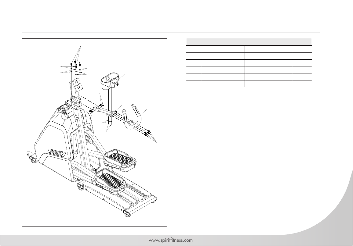
CE900ENT STEP ONE
54
54
57
65
9
57
65
54
58
54
46
10
99
11
HARDWARE FOR STEP 1
PART TYPE DESCRIPTION QTY
46 SELF-TAPPING SCREW
54 BOLT
57 LOCK WASHER
58 WASHER
65 WASHER
3.5x12
M10x1.5x20
10x16.5x2
4x14x1.0
10.2x19x1.5
2
12
4
2
4
1. Unwind wiring harness and run wires up through
CONSOLE MAST (9). Bolt CONSOLE MAST (9)
to MAIN FRAME (1) using 4 BOLTS (54), 4 LOCK
WASHERS (57), and 4 WASHERS (65). Do not
pinch wires.
2. Run wires from CENTER HANDLEBARS (11)
through HANDLEBAR BRACKET (10), into
CONSOLE MAST (9) and out the top.
3. Install CENTER HANDLEBARS (11) to
HANDLEBAR BRACKET (10) using 4 BOLTS (52).
4. Install HANDLEBAR BRACKET (10) to CONSOLE
MAST (9) using 4 BOLTS (54).
5. Attach CUP HOLDER (99) to HANDLEBAR
BRACKET (10) using 2 SELF-TAPPING SCREWS
(46) and 2 WASHERS (58).
7
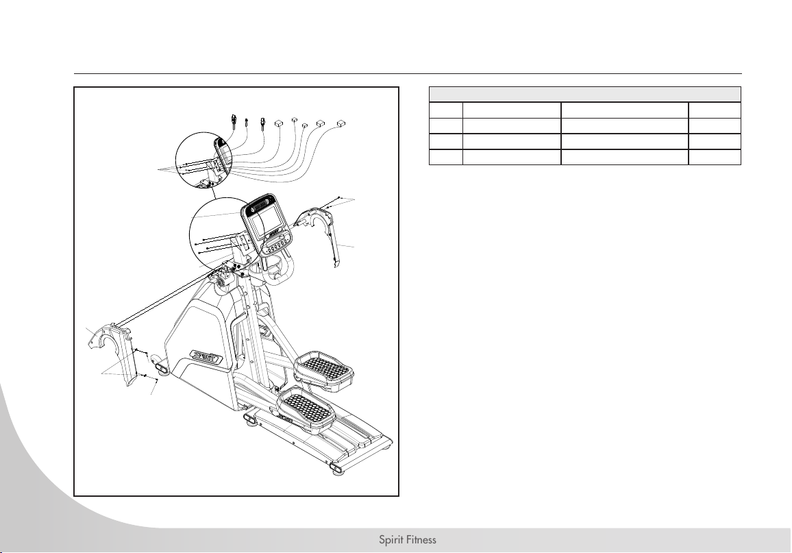
Spirit Fitness
101
100
78
47
47
49
130
121123 124 122
49
111
9
117
125
CE900ENT STEP TWO
HARDWARE FOR STEP 2
PART TYPE DESCRIPTION QTY
47 SELF-TAPPING SCREW
49 SCREW
78 U-NUT
5x16
M5x12
M5
2
6
2
1. Install 2 U-NUTS (78) to LEFT CONSOLE MAST
COVER (100).
2. Attach CONSOLE MAST COVERS (100 & 101) to
MAIN FRAME (1) using 2 SELF-TAPPING SCREWS
(47). Use 2 SCREWS (49) to connect covers to
each other.
3. Plug in all wires from wiring harness to CONSOLE
(111).
4. Install CONSOLE (111) to CONSOLE MAST (9)
using 4 SCREWS (49). Be careful not to pinch any
wires.
8
www.spirittness.com
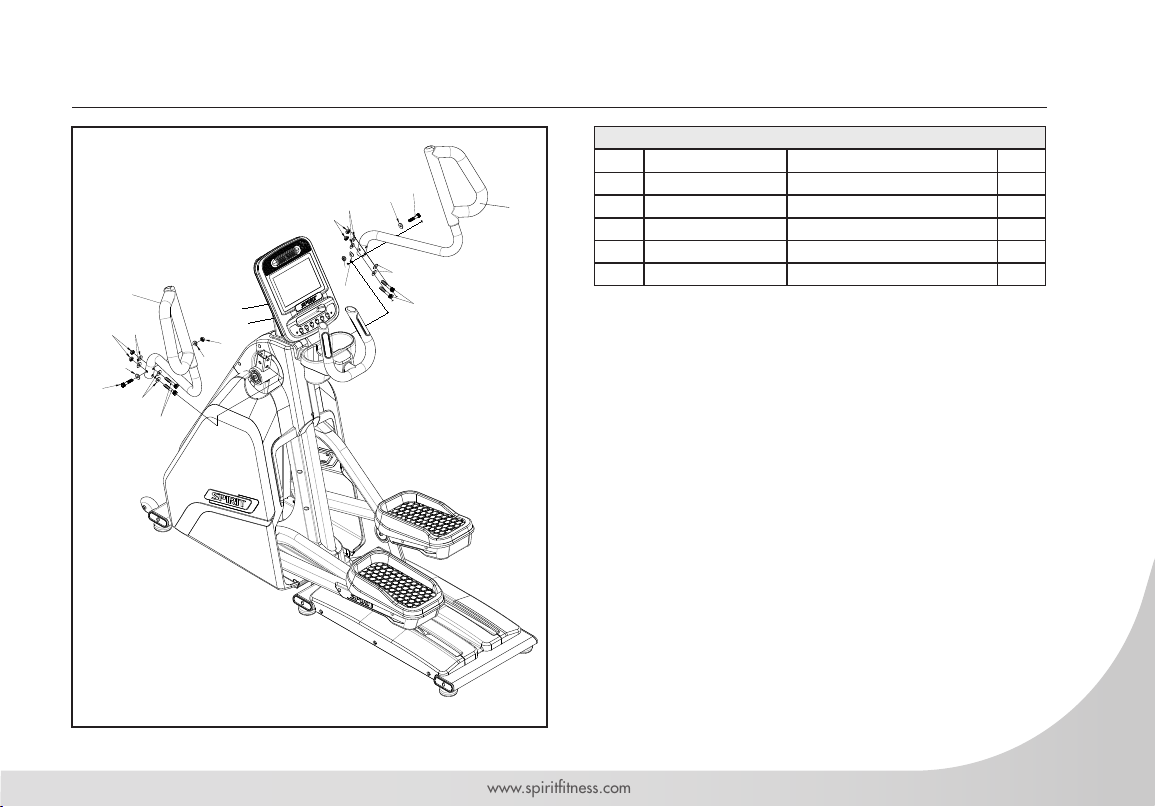
43
CE900ENT STEP THREE
43
71
63
2
63
63
44
68
71
71
71
68
63
63
63
44
3
HARDWARE FOR STEP 3
PART TYPE DESCRIPTION QTY
43 BOLT
44 BOLT
63 WASHER
68 CURVED WASHER
71 NUT
M10x5.5x
M10x6.0
10x25x1.5
10x23x1.5
M10x8
10
1. Install LEFT SIDE HANDLEBAR (2) to SWING
ARM (12).
a) First install 2 longer BOLTS (44) with a WASHER
(63) on both sides of SWING ARM (12) and a
NUT (71). Do not tighten yet.
b) Then install 1 SHORTER BOLT (43) with a
WASHER (63) through the SWING ARM (12)
and CROSSTRAINING HANDLEBAR (2), using
a CURVED WASHER (68) and a NUT (71) on
the back side.
c) Tighten after all hardware is installed.
2. Repeat process for RIGHT SIDE HANDLEBAR (3).
2
4
2
6
9
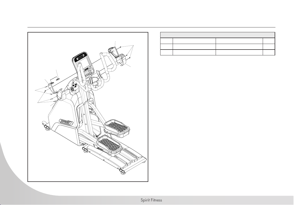
Spirit Fitness
91
92
93
93
98
49
46
49
CE900ENT STEP FOUR
HARDWARE FOR STEP 4
PART TYPE DESCRIPTION QTY
46 SELF-TAPPING SCREW
49 SCREW
3.5x12
M5x12
1. Attach CONSOLE BRACKET COVERS (91 & 92)
to CONSOLE MAST (9) using 2 SCREWS (49).
Connect covers together using 2 SELF-TAPPING
SCREWS (46).
2. Attach left SWING ARM HINGE COVER (93) to
SWING ARM (12) using 2 SCREWS (49). Repeat
for right side.
2
6
10
 Loading...