

Spirit Fires FR920HE Technical Installation Manual

Page 1 of 60
Spirit Fires Limited. 4 Beaumont Square, Aycliffe Industrial Park, Newton Aycliffe, County
Durham, DL5 6XN. Tel : 01325-327221 Web : www.spiritfires.co.uk
TECHNICAL INSTALLATION MANUAL
FR920HE
(HIGH EFFICIENCY GAS FIRE)
CE Approval: BSEN613:2001+A1:2003+C1:2008 & BS7977-
1:2009+A1:2013
CE Pin Number: 0558CP1693
The FR920HE is suitable for Natural Gas only.
Serial Number ………………………………
Please quote this serial number when calling to discuss your fireplace. To register your
installation please return the warranty card supplied with the fire.
This booklet contains the Instructions for Installation and
Maintenance and the User Instructions must be handed to
the User once the appliance has been commissioned. The
booklet should be retained for future reference.

Page 2 of 60
Spirit Fires Limited. 4 Beaumont Square, Aycliffe Industrial Park, Newton Aycliffe, County
Durham, DL5 6XN. Tel : 01325-327221 Web : www.spiritfires.co.uk
Contents
Page 3 Technical Data
Page 3 Appliance Efficiency Declaration
Page 4 Introduction and Installation Requirements
Page 7 Remote Control System
Page 8 Unpacking the Appliance
Page 8 Parts List
Page 8 Important Notes About the FR920HE Design
Page 9 Removing/Fitting the Glass Panel
Page 12 Removing/Fitting the Vanity Cover
Page 13 Installing the Gas Fire
Page 14 Version # 1 : BS-7977 : 2009
Page 22 Version # 2 : EN613 : 2001
Page 28 Commissioning Checklist
Page 29 Commissioning the Fire
Page 31 Log Set Layout
Page 35 Final Safety Check
Page 35 Warning Fire Guards and Hearths
Page 36 Fault Diagnosis/Troubleshooting
Page 38 Remote Control Components
Page 39 Remote Control – Error Codes
Page 39 Remote Control – Access/Heat Shields
Page 40 Service and Aftercare Requirements
Page 41 Servicing Instructions
Page 42 Spare Parts/Optional Extra
Page 43 Gas Fire User Instructions

Page 3 of 60
Spirit Fires Limited. 4 Beaumont Square, Aycliffe Industrial Park, Newton Aycliffe, County
Durham, DL5 6XN. Tel : 01325-327221 Web : www.spiritfires.co.uk
Technical Data
Approval EN613 : 2001
Approval BS7977 : 2009
Pilot Assembly Marking ERTA-82-650 [AC012]
Injector
82-600 (AC061) x1pc
Gas connection 8mm O.D. tube
Minimum flue diameter 125.0mm
Minimum flue height 2.0m
Room Ventilation [PAV] Not Required
Approximate weight 25kg
Gas Type* G20 – I2H – Natural Gas
Gas Pressure 20mBar
Nominal Heat Input 6.1 kW, Gross
Gas Flow Rate 0.581m3/hour
Nox Class Class 5
Efficiency Class Class 2
Efficiency Rating [Net] 77.7%
Efficiency Rating [Gross] SAP 70.0%
When replacing the Injector or Pilot assembly this must be purchased from the
manufacturer. Review the sections in the booklet relating to replacement parts
by the user and qualified installer.
Appliance Efficiency Declaration
The efficiency of this appliance has been measured as specified in EN
613:2001 - Independent gas-fired convection heaters. The Gross calorific
value of the fuel has been used for this efficiency calculation. The test data
from which it has been calculated has been certified by Gastec at CRE Limited
[notified body number 0558]. The efficiency value may be used in the UK
Government’s Standard Assessment Procedure (SAP) for energy ranging of
dwellings

Page 4 of 60
Spirit Fires Limited. 4 Beaumont Square, Aycliffe Industrial Park, Newton Aycliffe, County
Durham, DL5 6XN. Tel : 01325-327221 Web : www.spiritfires.co.uk
Introduction & Installation Requirements.
Consumer Protection Information
As the manufacturer and supplier of heat products, we take every care, as far
as is reasonably practicable, that these products are so designed and
constructed as to meet the general safety requirement when properly used and
installed. To this end, our products are thoroughly tested and examined before
dispatch. IMPORTANT NOTICE: Any alteration that is not approved by the
appliance manufacturer could invalidate the approval of the appliance,
operation of the warranty and could affect your statutory rights.
Health and Safety Notice
Important: This appliance could contain some of the materials, indicated
below, that could be interpreted as being injurious to health and safety. It is
the users / installers responsibility to ensure that the necessary personal
protective clothing is worn when handling these materials, see below for
information.
Artificial Fuels, Mineral Wool, Insulation Material, Refractory/Ceramic
Fibres, Glass Yarn – may be harmful inhaled, may be irritating to skin, eyes,
nose and throat.
When handling avoid inhaling and contact with skin or eyes. Use disposable
gloves, facemasks and eye protection. After handling wash hands and other
exposed parts. If a vacuum is used for cleaning the coals or cleaning after
servicing / installation it is recommended that it be of the type fitted with a
HEPA filter.
• The FR920HE has been designed and tested to the requirements of EN613
and BS7977-1:2009 and is suitable for use in all EU countries with matching
gas categories.
• The FR920HE is a high efficiency gas fire for use with a chimney or flue
system.
• The FR920HE incorporates a single gas control, which selects ignition pilot,
with variable setting between low and high settings and is operated via
remote control hand set. The system is powered by a battery pack therefore
no mains electrical supply is required.
• Like all appliances incorporating an aerated burner a low frequency noise
may be heard, this may be more noticeable on the low setting.
• The FR920HE incorporates a safety device in the form of an Oxygen
Depletion System, which constantly monitors the oxygen in the room and
will cause the fire to switch off if the oxygen level reduces, for instance due
to a blocked flue. If this regularly occurs do not attempt to relight the
appliance until a qualified engineer has checked it.
• The installation must be carried out by a Gas Safe registered engineer in
accordance with National Regulations.

Page 5 of 60
Spirit Fires Limited. 4 Beaumont Square, Aycliffe Industrial Park, Newton Aycliffe, County
Durham, DL5 6XN. Tel : 01325-327221 Web : www.spiritfires.co.uk
• Clearances between the fire and all combustible materials must conform to
National Regulations.
• This appliance is supplied as a complete fireplace package including gas fire
burner unit, enclosure and fascia. This fire must be installed and used in
accordance with these instructions.
• The builders opening or fireplace opening must be constructed of a non-
combustible material.
• For some countries a non-combustible hearth must be fitted in front of the
fire in accordance with National Regulations (e.g. United Kingdom).
• Flue System: The FR920HE can be used with a brick/precast chimney or
using a flue liner with a minimum diameter of 125mm (5”). If installing in a
chimney this should be inspected prior to installation to ensure it is working
correctly. If the chimney has previously been used with a solid fuel
appliance it will also require sweeping. Consult a flue specialist to inspect
and test the flue prior to installation. The chimney must have a minimum
effective height of at least 2 metres. This is not necessary if the flue has
previously been used with a gas appliance or if it is a new installation. (see
technical section for full details on the flue requirements). Any flue damper
plate or flue restrictor must be removed.
• Gas Supply: This appliance is intended for use on a gas installation with a
governed meter. The FR920HE is available for Natural Gas only. Inlet is via
an 8mm connection via the isolation valve provided with the fire. The gas
connections must be in accordance with National Regulations. If the gas line
is longer than 1.5mtrs then the gas line should be increased in diameter to
15mm and possibly larger depending on the final length to ensure a steady
gas supply. The fire is supplied with an isolation valve inside the appliance.
This must be used. When closed this will allow the complete burner and
control assembly to be disconnected for maintenance or repair in
accordance with National Regulations.
• The pilot light and flame sensing device fitted to this fire is also an
atmosphere sensing device. If for any reason any part of the pilot assembly
is to be replaced ALL the assembly including the pilot burner, thermocouple,
electrode and injector must be exchanged complete for an original
manufacturer’s pilot assembly only. This atmosphere sensing device is not
adjustable and must not be put out of action. The pilot light shuts off both
the main burner and pilot if evacuation of the combustion products is
interrupted (blocked chimney). If the flame supervision device operates
no attempt should be made to re-light the gas fire until at least 3
minutes have elapsed. To relight the fire consult page 52. If the
device operates again do not use the fire until the reason for operation is
found – consult a Gas Safe Engineer.
• The FR920HE is battery operated; therefore no mains electrical supply is
required. Power to the appliance is provided by 3 high power alkaline 1.5V
batteries (AA size) these batteries can be changed to Nickel Metal Hydride
rechargeable batteries providing they have a minimum capacity of 2200
mAh. A set of high power alkaline batteries (AA size) will last a minimum of
1 year. The life of the battery will depend on how the appliance is used and

Page 6 of 60
Spirit Fires Limited. 4 Beaumont Square, Aycliffe Industrial Park, Newton Aycliffe, County
Durham, DL5 6XN. Tel : 01325-327221 Web : www.spiritfires.co.uk
the battery manufacturer and quality. The fire is operated by the handset
provided. Please take some time to learn the lighting procedure and
operation of the hand set. The handset uses 2 x 1.5v AA batteries. The
handset shows the condition of the batteries. (see section on remote system
and changing batteries).
• The chimney or flue (unless new or previously used with a gas appliance)
must be swept before installation if it has been used for solid fuel.
• The fire is supplied as “frame-less” to create a letterbox style opening in the
wall. If choosing to fit a stone trim around this great care must be taken of
the choice of stone and the bonding method to ensure the stone is safely
fitted to the wall and cannot crack with heat.
• Failure to install the appliance correctly could lead to prosecution. In GB
(Great Britain), the appliance must be installed by a competent person i.e.
GAS SAFE registered, in accordance with the GAS SAFETY (INSTALLATION
AND USE) REGULATIONS, the building regulations (or the building
regulations (Scotland) or the building regulations (Northern Ireland). In IE
(Ireland), the appliance must be installed by a competent person and
installed in accordance with the current edition of I.S.813 Domestic Gas
Installation, the current building regulations.
• Glass: The glass front of this fire acts as a dress guard, conforming to BS
1945 (1997) however, a fireguard conforming to BS6539 (1997) must be
used to protect young children, the elderly or infirm. The appliance MUST
NOT be used if the glass safety screen is broken, removed or is open.
• Smells: During initial usage, an odour may be evident. This is the starch
binder used during the manufacture of the fibre components of the fire, and
there are no harmful effects produced.
• Flame: During initial starting of the appliance condensation may be seen on
the glass and the flame may be unstable or blue. This is normal with this
type of appliance and will disappear when the fire and flue system are
warm.
• During the normal operation of the fire some staining may appear on some
parts of the fire burner. This is quite normal due to the heat generated by
the appliance.
• This is a high efficiency gas fire and generates a considerable amount of
heat from the top of the appliance. Care must be taken to prevent any
damage being caused to surrounding soft furnishing or decoration, e.g.
many embossed vinyl wall coverings may become discoloured if placed too
close to the appliance. Combustible material i.e. wall panelling or wallpaper
must be removed from behind the fire and fire trim.
• It is advised that this appliance is serviced annually (every 12 months), as it
is more likely to provide trouble-free operation.
• The fire does not require purpose built permanent ventilation as it conforms
to BS 5871-2: 2005 +A1: 2007 – Annex B (has a net heat input of ≤7kW
and a flue flow of ≤70m3/h
• This appliance becomes hot during operation therefore all areas must be
considered to be working surfaces.
Page 7 of 60
Spirit Fires Limited. 4 Beaumont Square, Aycliffe Industrial Park, Newton Aycliffe, County
Durham, DL5 6XN. Tel : 01325-327221 Web : www.spiritfires.co.uk
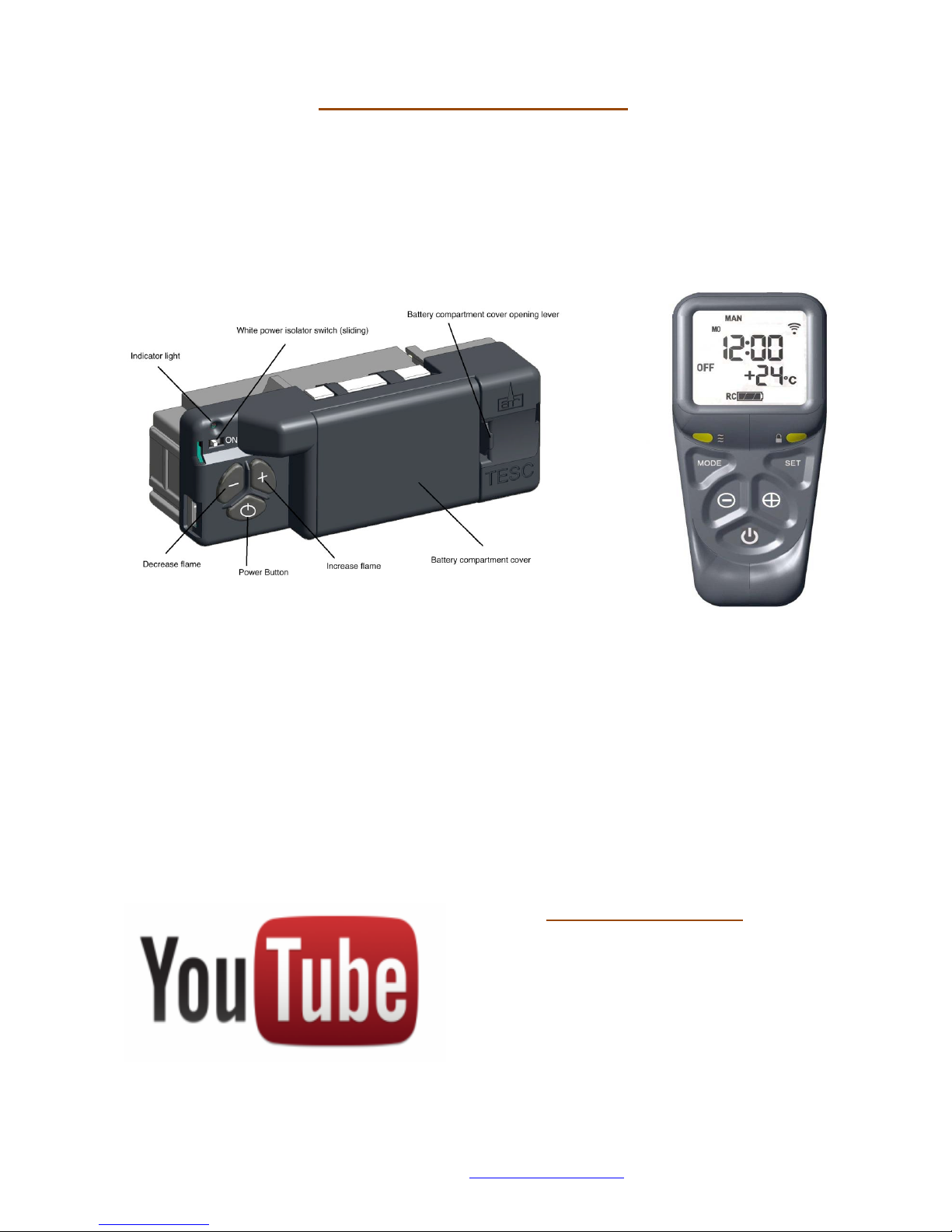
Remote Control System
Take some time to learn about the remote system fitted to this fire.
The remote system features an RF (radio frequency) handset. The handset and
the remote black box must be matched together to work correctly. Read the
full section later in this manual to ensure you understand how the remote
system works. The handset with a screen will also show any error codes which
occur.
The Handset is powered by 2 x AA batteries; the Main remote system has 3 x
AA batteries. Always use high quality alkaline batteries to ensure a long life
and reliable performance. The batteries will last a minimum of 12 months or
longer however it is advised to ask you gas installer to replace the batteries on
each 12 month service. The handset will switch the fire on/off and regulate the
flame up/down. The hand set has a child safe feature to avoid accidental
lighting. YOU MUST HOLD THE HANDSET IN THE PALM OF YOUR HAND TO
SWITCH ON THE HANDSET. THIS IS INDICATED BY A GREEN LIGHT ON THE
RIGHT HAND SIDE.
Please read “lighting the fire” section later in this handbook before operating
the appliance.
HELP IS AVAILABLE
There are videos on YouTube that
can be used to help you set up and
use this remote system. Search on
YouTube for “TESC GAS CONTROL”
and you will find a series of
instructional videos on how to set up
and use the hand set.

Page 8 of 60
Spirit Fires Limited. 4 Beaumont Square, Aycliffe Industrial Park, Newton Aycliffe, County
Durham, DL5 6XN. Tel : 01325-327221 Web : www.spiritfires.co.uk
Unpacking the Appliance
Read these instructions fully before starting to install the fire.
Carefully examine the carton for any exterior transport damage, if in doubt
consult the manufacturer before proceeding. Remove the gas fire and examine
its general condition. If it has any damage is visible contact the supplier to
get instructions on how to proceed. If fully satisfied by the condition of the
appliance then proceed with the installation.
Please Note that no claims will be accepted for damaged or marked
goods once the appliance has been installed.
Parts List
• The gas fire is supplied as a self contained gas fire including:
o Gas Appliance
o Ceramic Set [logs or pebbles as purchased]
o Installation Booklet.
o Remote Handset.
o Battery Pack.
o Fitting Kit.
If any of the above are missing please consult the supplier before proceeding.
Important Notes about the FR920HE Design
Gas Burner : The FR920HE has a modern gas burner with a ribbon of flame.
It is supplied with a log set and special wool to create a sparkling ember effect.
The logs and wool must be positioned exactly as shown in the manual. The gas
burner features a sensitive pilot assembly. Never tamper with the pilot
assembly or shield. Only use manufacturer supplied parts. When performing
repairs on this gas appliance.
Installation Style : The FR920HE is a high efficiency gas fire built to the
latest approval standards. The fire is tested to different approval standards
depending on how it will be installed. Review the paperwork supplied with the
fire to identify which version has been purchased by the customer. Each
version has a different set of installation instructions. The fire is supplied from
the factory pre-set for the type of install. It cannot be converted at a later
date. For this reason the fire is supplied to site as the following models:
• FR920HE-BS7977
• FR920HE-EN613

Page 9 of 60
Spirit Fires Limited. 4 Beaumont Square, Aycliffe Industrial Park, Newton Aycliffe, County
Durham, DL5 6XN. Tel : 01325-327221 Web : www.spiritfires.co.uk
Remote Control System: The fire uses an RF remote system to operate this
is a new and modern design new to the market.
The hand set supplied must be held in the palm of your hand for a few seconds
until the safety lock is removed and the green light comes on. The hand set will
indicate room temperature, the current flame setting – high to low – the
battery levels in the main unit and the hand set and also the error codes when
there is an issue. The error codes are shown in the troubleshooting section of
the manual.
Take some time to read how the remote handset operates before
trying to use the appliance.
Glass Panel: The design has been created to hide the fixings for the glass. At
first it may seem difficult to remove the glass however it is very
straightforward if the instructions are followed. Take some time to learn how
the glass is removed and fitted.
Before starting to install the fire the glass panel must be removed. Once
removed from the fire ensure the glass is stored safely until it is required.
Removing/Fitting the Glass Panel
The glass is easy to remove as long as the steps set out below and images are
followed.
To remove the glass a 13mm open ended spanner is required. DO NOT
REMOVE THE BOLTS. DURING THE REMOVAL PROCESS THERE SHOULD BE
NO NEED TO TOTALLY REMOVE THE BOLTS. IF THE BOLTS ARE REMOVED IT
WILL BE DIFFICULT TO REFIT THEM TO THE FIRE.
When removing the glass great care needs to be taken with handling of the
glass. Ceramic glass is very brittle and is easily cracked or chipped. If the glass
is damaged in any way then a replacement piece must be purchased from the
manufacturer of the gas fire. No other glass is allowed to be used on the fire.
Using non-manufacturer glass on the fire will negate the CE approval and
render the appliance dangerous. The warranty is also void.
Ensure that the seal around the glass is not damaged or broken. If any damage
exists a new seal will be required from the manufacturer before fitting the glass
to the fire.
Page 10 of 60
Spirit Fires Limited. 4 Beaumont Square, Aycliffe Industrial Park, Newton Aycliffe, County
Durham, DL5 6XN. Tel : 01325-327221 Web : www.spiritfires.co.uk
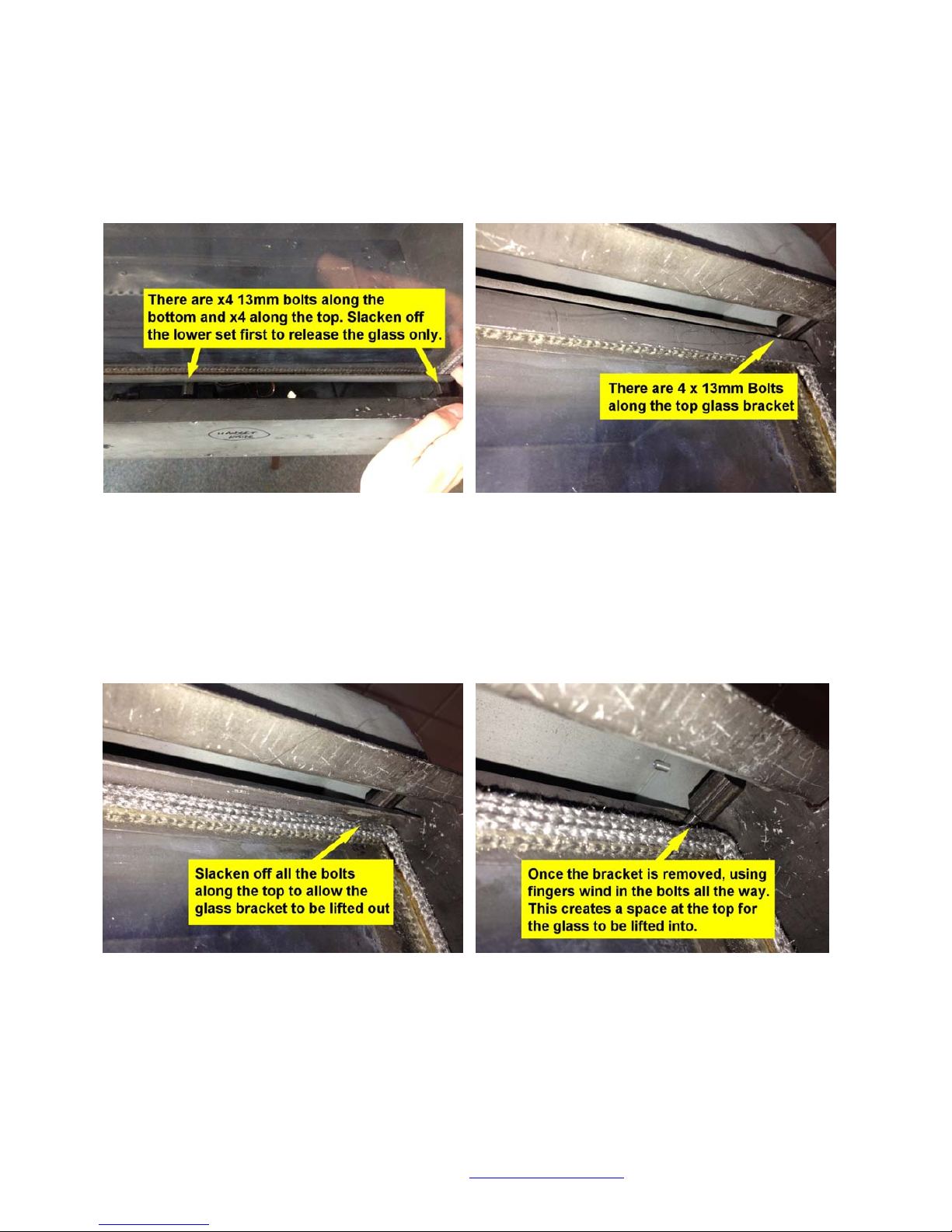
Glass Removal
1. Remove the side pieces and front air grille.
2. Slacken off the bottom row of bolts to loosen the lower glass bracket and
the hold on the glass.
3. Slacken off the top row of bolts until the top bracket is loose enough to be
flipped forward and pulled out.
4. The glass will now fall forward.
5. Screw the top bolts back in using fingers until seated – they do not have to
be tight. This creates a gap at the top.
Page 11 of 60
Spirit Fires Limited. 4 Beaumont Square, Aycliffe Industrial Park, Newton Aycliffe, County
Durham, DL5 6XN. Tel : 01325-327221 Web : www.spiritfires.co.uk
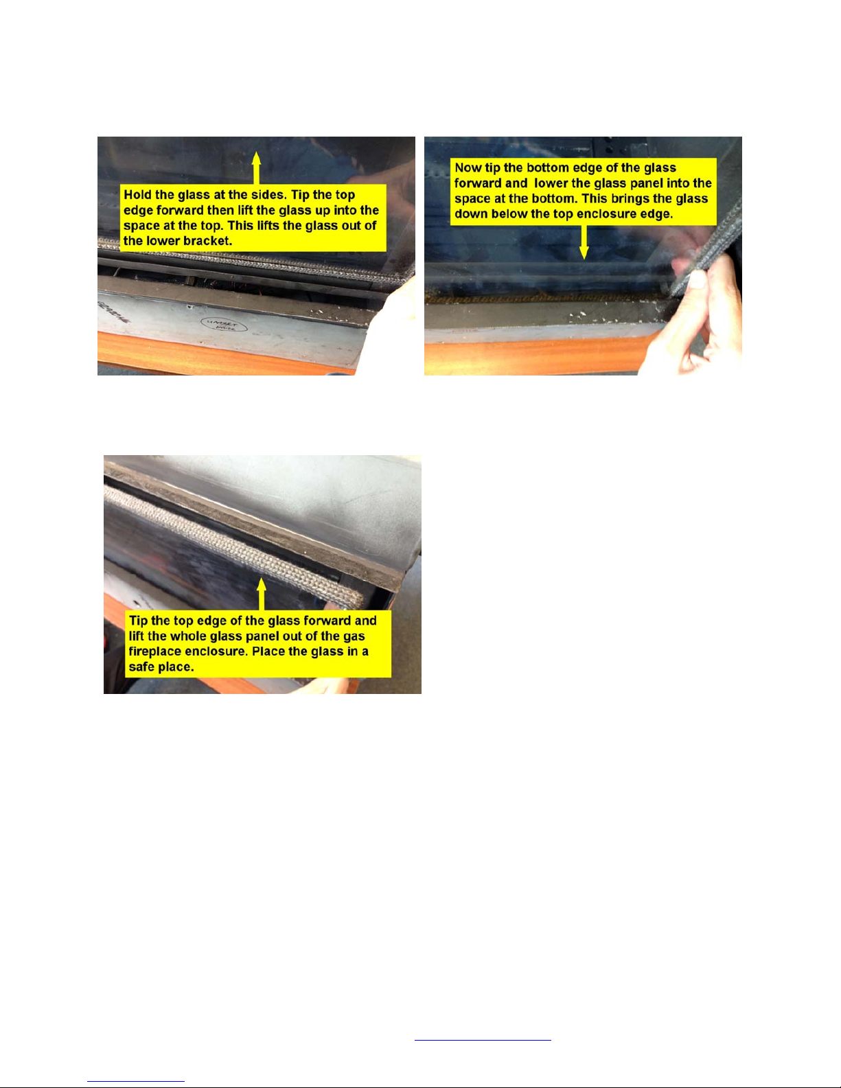
6. By holding the glass on both sides lift the glass out of the lower bracket by
moving it up into the gap between the top row of bolt heads and the
fireplace front.
7. Once the glass is clear of the lower bracket it can be lowered down again
into the gap created at the bottom between the lower bolt heads and the
fireplace front.
8. While holding the glass flip the glass top forward and lift out the glass panel.
9. Ensure the glass is stored in a safe place.
Fitting the Glass
Refitting the glass is a reversal of the above procedure.
Page 12 of 60
Spirit Fires Limited. 4 Beaumont Square, Aycliffe Industrial Park, Newton Aycliffe, County
Durham, DL5 6XN. Tel : 01325-327221 Web : www.spiritfires.co.uk
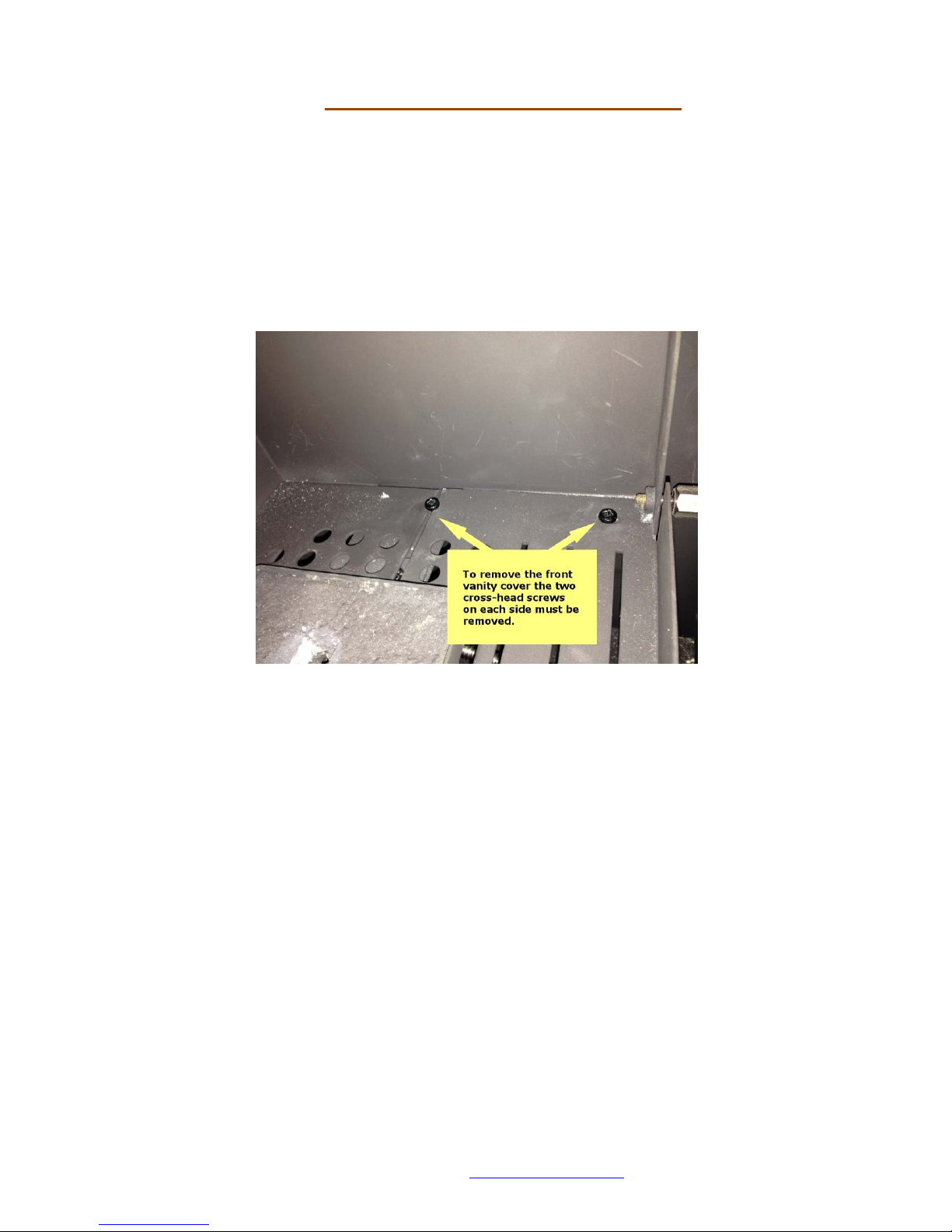
Removing the Vanity Cover
Once the glass is removed the front section of the vanity cover can be taken
out by removing the front machine screws on either side. The vanity cover can
then be lifted on one side and removed from the enclosure. This then allows
access to the burner tray and remote system.
Do not remove the screws at the back.
To refit the vanity cover just lift the cover back in and fix with the screws.

Page 13 of 60
Spirit Fires Limited. 4 Beaumont Square, Aycliffe Industrial Park, Newton Aycliffe, County
Durham, DL5 6XN. Tel : 01325-327221 Web : www.spiritfires.co.uk
APPLIANCE INSTALLATION
Prior to installation, ensure that the local distribution conditions (identification
of type of gas and pressure) and adjustment of the appliance are compatible.
Installation must be carried out by a Gas safe registered engineer and must
adhere to national and local legislations and regulations.
The appliance installation should be in accordance with the current version of
BS 5871-2, (which is BS5871-2: 2005 +A1: 2007 for the installation and
maintenance of gas fires, convector heaters, fire/back boilers and decorative
fuel effect gas appliances- Part 2: Inset live fuel effect gas fires of heat input
not exceeding 15kW, and fire/back boilers).
As stated in the section above there are two versions of this fire:
Version 1 – BS7977 – the fire is designed to be installed into a fireplace
opening with a brick built or pre-cast chimney. The fire is a cartridge that must
be used in a suitable fireplace chamber and sealed.
Ventilation into the recess is provided via the appliance chassis design and the
debris inspection plate in the lower section of the gas fire. This inspection plate
has a 20mm ventilation hole. This must not be blocked. This plate should be
removed during servicing to clear any debris which has collected in the
chimney during normal use. Once cleaned the plate must be replaced.
If installing this fire to BS7977 go to page 10
Version 2 –EN613 – the fire is designed to be used in a new build property
without a chimney. The fire is pre-fitted with a special flue box. This is then
connected to a 125mm flue liner. The fireplace is then built around using stud
work and boards to create a false chimney breast.
If installing this fire to EN613 go to page 21

Page 14 of 60
Spirit Fires Limited. 4 Beaumont Square, Aycliffe Industrial Park, Newton Aycliffe, County
Durham, DL5 6XN. Tel : 01325-327221 Web : www.spiritfires.co.uk
Installing the BS7977 Version of the Gas Fire
Dimensions
The BS7977 version of the fire is supplied to site as above. Note the
dimensions of the fireplace.
Remove the glass as shown on page 10, ensure the glass is stored
safely.
The fireplace can be damaged by dust and building materials. It is
strongly advised to protect the inside of the fire when doing any building
or construction work while installing the fire.

Page 15 of 60
Spirit Fires Limited. 4 Beaumont Square, Aycliffe Industrial Park, Newton Aycliffe, County
Durham, DL5 6XN. Tel : 01325-327221 Web : www.spiritfires.co.uk
Before Starting
Building work should only commence after a thorough survey of the intended
location of the impending installation has been completed and it has been
established that the unit can be installed and operated without risk to the
owner or tenants of the property or their neighbours.
Chimney
The BS7977 version of the is intended to be used within an brick built chimney
or a brick chimney lined with a flue liner. This must have a minimum diameter
of 125mm [or equivalent area] and a minimum length of 2 metres. If the
chimney has been used previously with a solid fuel fire this must be swept
before installation of the gas appliance. It is advised to perform a smoke test
prior to installation to confirm the chimney is working correctly. The flue must
be sealed to the fireplace enclosure in line with building regulations.
Gas Supply
Consult the Data Plate within the appliance to ensure the correct gas type and
pressure is available within the property. Before commencing to create the
fireplace opening for the inglenook unit note that a gas supply is required. The
gas supply pipe should run into the installed enclosure from either the rear, left
or right hand sides, the gas supply is best run through the left side of the
enclosure.
The fire has an 8mm inlet with an isolation valve and pressure test point within
the appliance. This pressure test point is used when commissioning the
appliance. The gas pipe work should be routed into the enclosure via the
available access holes. If the gas pipe work is over 1.5mtrs in length it is
recommended that the pipe work is increased in diameter from this point to
15mm and possibly 22mm depending on the length to the meter. This will
ensure a stable gas supply.
Hearth
If this appliance is to be fitted above a hearth the base of the opening
must be a minimum of 50mm from the hearth.
If the fire is to be fitted without a hearth the minimum height from the
base of the fire is 100 mm.
When operating the glass on the fireplace becomes very hot. A hearth should
be considered if the fireplace is to be mounted at a height where contact with
the glass may cause injury. See section in manual.
Page 16 of 60
Spirit Fires Limited. 4 Beaumont Square, Aycliffe Industrial Park, Newton Aycliffe, County
Durham, DL5 6XN. Tel : 01325-327221 Web : www.spiritfires.co.uk
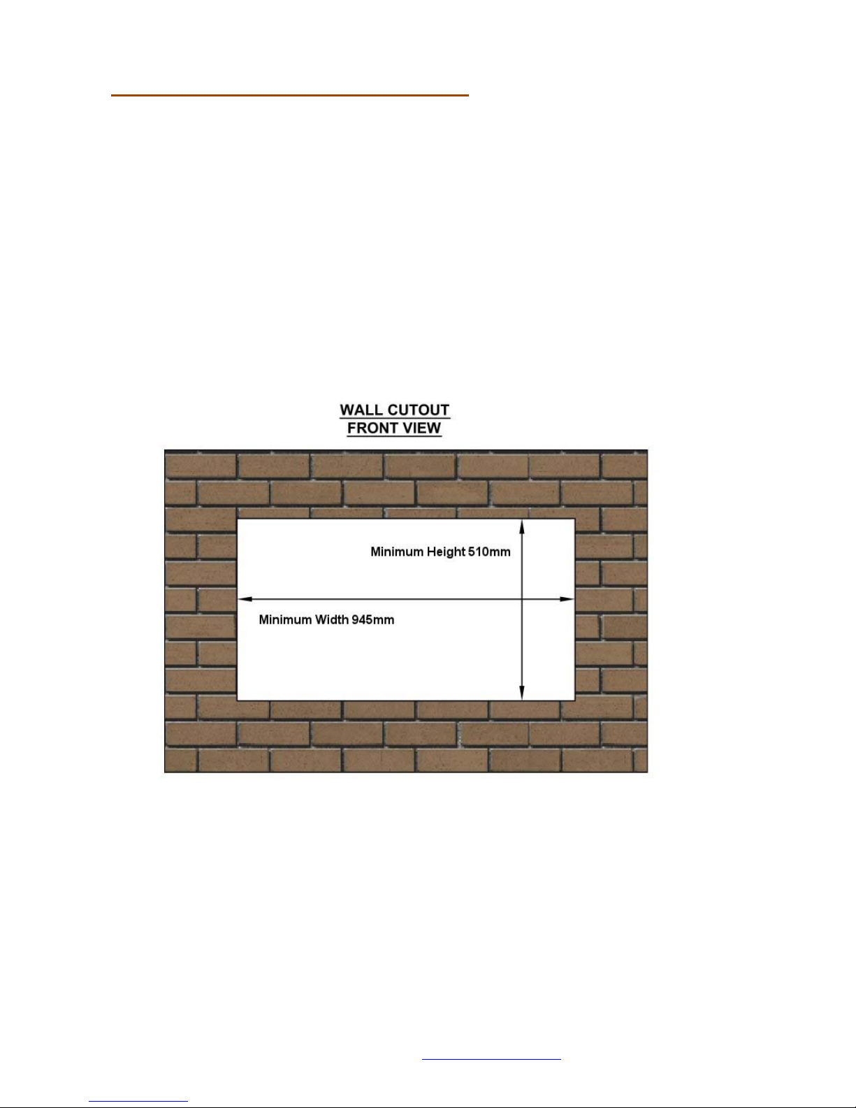
Building Work / Fireplace Opening
Measuring from the floor surface, the intended location of the base of the
enclosure unit is marked onto the wall. The fireplace opening should be located
centrally to the existing flue / chimney at your desired height. The area
indicated on the wall must be removed to create an opening to house the
fireplace. In some installations it may be necessary to install a lintel above the
opening, if so an allowance must be made to accommodate this lintel. (The
Fire does not have its own lintel).
The base of the chamber must be able to withstand the weight of the appliance
and must be sealed to ensure that all combustion products enter the flue.
Note: The base must be level – if the base is not level the flame will not be
central in the fireplace and the user will most likely complain.
Page 17 of 60
Spirit Fires Limited. 4 Beaumont Square, Aycliffe Industrial Park, Newton Aycliffe, County
Durham, DL5 6XN. Tel : 01325-327221 Web : www.spiritfires.co.uk
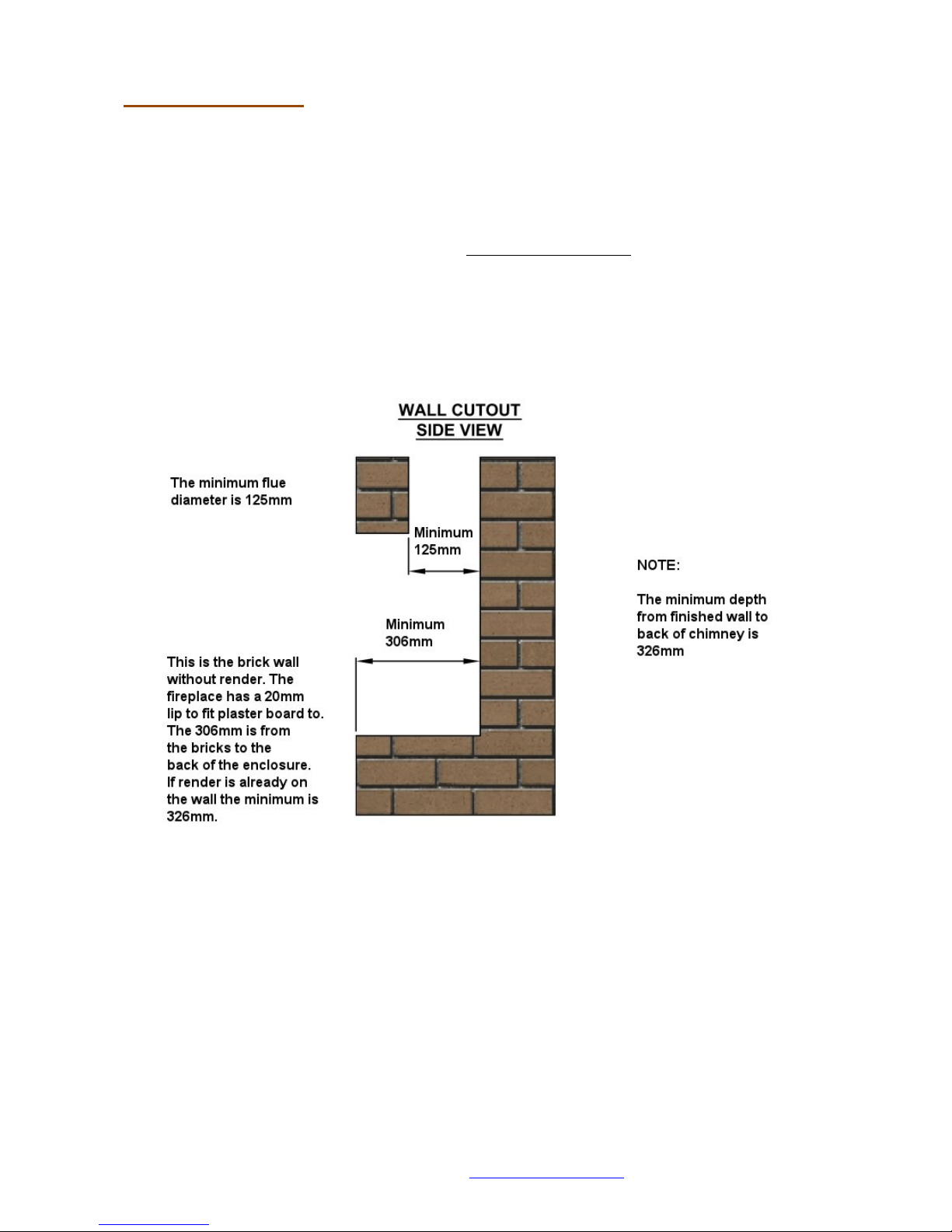
Fireplace Depth
To comply with BS7977-1 a minimum depth of 326mm is required. This
dimension is from the finished wall to the back of the fireplace opening.
See below image for the construction opening size.
Note: The image shows the brick wall without the render. The fireplace has a
20mm lip to allow the plaster board to be fitted flush to the fireplace to create
a letterbox design.
When measuring the fireplace opening the MINIMUM DEPTH FROM
FINISHED WALL TO BACK OF FIREPLACE OPENING IS 326MM
Page 18 of 60
Spirit Fires Limited. 4 Beaumont Square, Aycliffe Industrial Park, Newton Aycliffe, County
Durham, DL5 6XN. Tel : 01325-327221 Web : www.spiritfires.co.uk
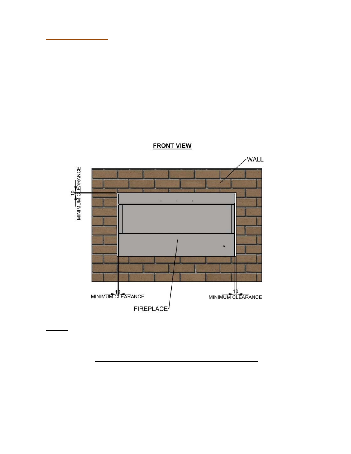
Fitting the Fire
Before fitting the fire run an 8mm gas line into the chamber ready for
connection to the fire. The fire is supplied as a cartridge. Once a noncombustible chamber has been created in line with the required dimensions the
fire can be lifted into the opening and secured to the chamber.
To gain access to the fire box chamber remove the vanity cover as shown on
page 12. Store the vanity cover safely so it cannot be damaged.
The gas pipe should be fed through the appropriate hole in the enclosure ready
to connect to the isolation valve. See images below.
NOTE:
There must be a clearance of 10mm above the fireplace
.
There must be a clearance of 10mm on each side of the fireplace.
 Loading...