

Spirit Fires FR850-NV, FR850-V Technical Manual & User Handbook

Page 1 of 54
PIN NUMBER: 0558CP1695
Rev 4
FR850-V & FR850-NV
[With ANTOSS Remote]
TECHNICAL MANUAL & USER HANDBOOK
CE APPROVAL: BS EN509:2000+A1:2003+A2:2004
Serial Number ………………………………
For use with Natural Gas (G20) or LPG (G31) – refer to dat apl ate
Important: It is recommended, even if you have fitted these appliances
before, that you take the time to r ea d through these instructions and follow
them step by step.
Please quote this serial number when calling to discuss installation and spare
part requests. The Warranty is valid for 1 Year from date of delivery.
To register the appliance complete the warranty card supplied and return to:
Spirit Fires Limited. 4 Beaumont Square, Aycliffe Industrial Park,
Newton Aycliffe, County Durham, DL5 6XN.
This manual must be handed to the owner of the property once the
appliance has been installed and commissioned

Page 2 of 54
Contents
Page 4 Technical Data
Page 5 Description
Page 5 Read This First
Page 6 Unpacking the Appliance
Page 6 Parts List
Page 7 Construction Drawings
Page 8 Gas Burner Construction
Page 9 Remote Control System
Page 10 Installation Requirements
Page 12 Building & Installation Work
Page 20 Commissioning the Appliance
Page 22 Fitting the Logs.
Page 25 Fitting the Pebbles.
Page 26 Final Safety Check List.
Page 27 Commissioning Sheet.
Page 28 Fire Guards & Hearths
Page 29 Technical: Fault Diagnosis & Troubleshooting
Page 30 Hand Set Error Codes
Page 30 Typical Faults and Solutions
Page 31 Pilot Assembly Explained (ODS)
Page 31 Spark or Ignition Failure
Page 32 Burner Flame
Page 32 Remote Control Parts
Page 33 Service and Aftercare Requirements
Page 34 Servicing Instructions
Page 35 Spare Parts / Components List
Page 37 Gas Fire User Instructions
Page 3 of 54
Description of FR-850 Design
This appliance is supplied as a complete suite of gas fire burner unit with
remote control and enclosure, there is an optional gather. To comply with the
approval this fire must be installed as designed. There are two versions which
can be purchased by the customer depending on site specific conditions like
chimney size and room ventilation. Read this booklet carefully and check the
delivery paperwork and data plate inside the fire to confirm which version is to
be installed.
The versions are:
• FR850 – (Natural Gas or LPG) - This version has a minimum flue
requirement of 178mm diameter or Class 1 chimney at 2m in length. This
version needs room ventilation with a 100cm2 air vent to the outside air.
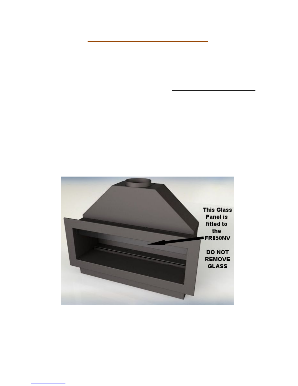
• FR850NV – (Natural Gas Only) - This version has a mi nimum flue size of
127mm diameter flue or Class 2 chimney at 3m in length. This version does
not need room ventilation. The enclosure on this version features a glass
panel to reduce the opening. This glass panel must be fitted at t he factory at
time of order. This version of th e fire must not be operated without the glass
panel fitted.
If the fire has been delivered to site with the glass panel then the
fire must never be operated without the glass in place. Refer to the
Data Plate. If the glass is damaged a replacement must be
purchased from the manufacturer.
Page 4 of 54
Technical Specification
Important Note: This fire is available in various designs, check delivery
paperwork and the data plate on the fire to confirm which version has
been purchased.
MODEL
FR-850-V
FR-850-V
FR-850-NV*
Gas Type
LPG Natural Gas
Gas Category
I3P I2H
Gas Type
G31 G20
Inlet Pressure (mbar)
37 20
Injector 145 x 1pc 600 x 1pc
Oxypilot ERTA PG-82-390 ERTA PG-82-650
Gas Rate, (Gross,
kW) FULL
7.4 kW 7.4 KW
Gas Flow Rate (m3/h)
0.278 m3/h 0.705 m3/h
Gas Connection 8mm
Appliance Mass 20kg
Gas Valve Control Unit
TESC01 RF 868-15
TESC Setup Code 228407
Remote Transmitter RF868D
Countries of
Destination
The FR850 is CE approved for installation in the following
European Countries with I2H Gas @ 20mBar or I3P Gas @
37mBar. AT, BG, CH, CZ, DK, EE, ES, FI, GB, GR, HR, IE,
IT, LT, LV, NO, PT, RO, SE, SI, SK, TR
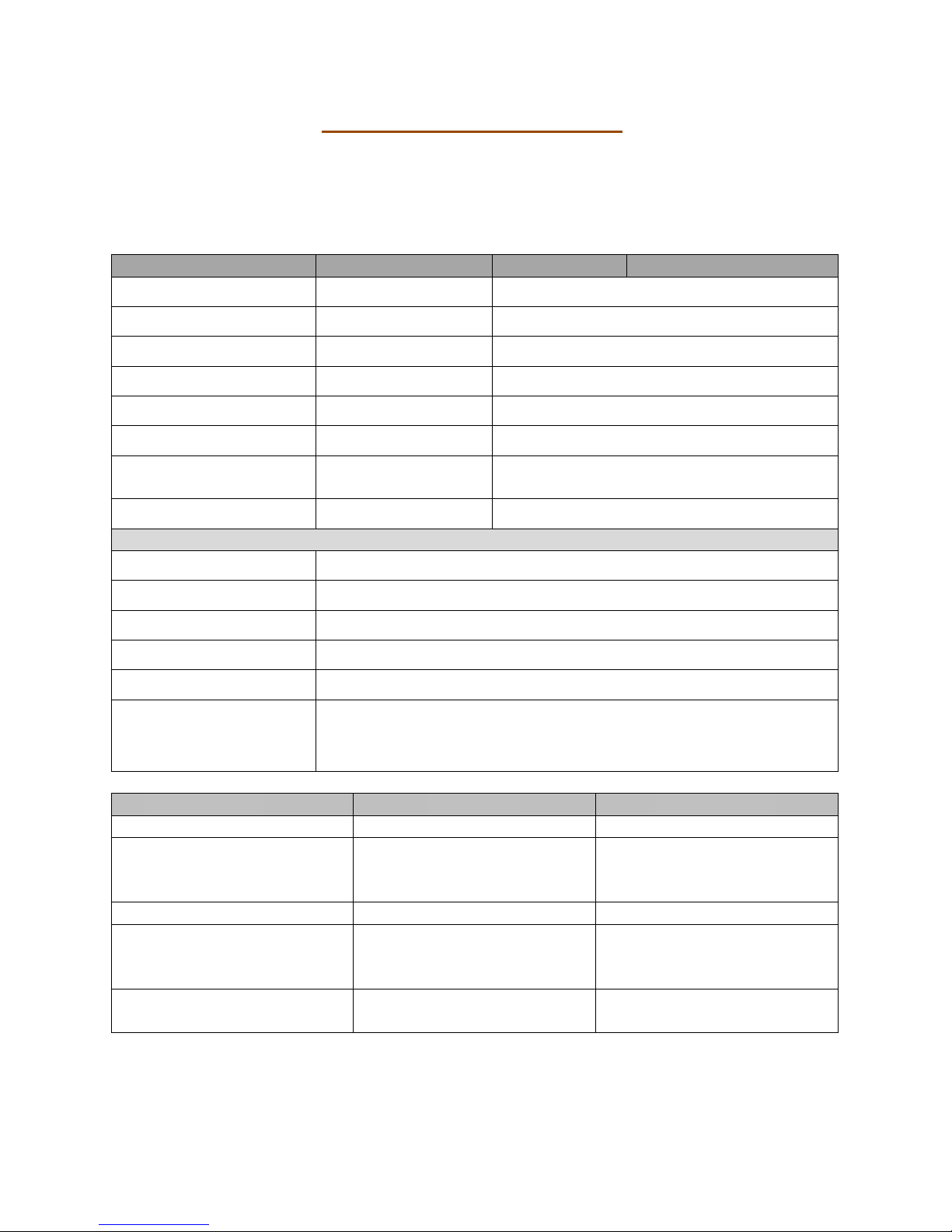
ENCLOSURE
FR-850-V
FR-850-NV*
Enclosure Opening
852 x 265 x 313
852 x 200 x 313*
Minimum Flue
Requirements
Using Flue Liner
177.8mm diameter with
2m length or Class 1
Chimney
127.0mm diameter with
3m length or 177.8mm
with 2m length
Minimum Chimney
Class 1 Chimney
Class 2 Chimney
Room Air
Vent
Required
YES NO
Room Vent Size
[free air]
100cm2
*FR-850-NV is a special version of the fire with glass panel at the
top to reduce the opening size. This fire does not need a room
vent and is only available for Natural Gas.

Page 5 of 54
Description of FR-850 Design
This appliance is supplied as a complete suite of gas fire burner unit, enclosure
and fascia. To comp ly with the approval this fire must be installed as designed.
There are two versions which can be purchased by the customer depending on
site specific conditions like chimney size and room ventilation. Check the data
plate to confirm which version is to be installed. The versions are:
• FR850-V - This version has a minimum flue requirement of 178mm
diameter or Class 1 chimney at 2m in length. This version needs room
ventilation with a 100cm2 air vent to the outside air.
• FR850-NV – This version has a minimum flue size of 127mm diameter flue
or Class 2 chimney at 3m in length. This version does not need room
ventilation. The enclosure on this version features a glass panel to reduce
the opening. This glass panel must be fitted at the factory at time of order.
Read This First
• Gas Supply: Do not in stall the fire until the gas pipework has b een checked
and a flow rate performed to ensure that the minimum flow rate specified in
the technical section can be maintained when the fire operates on full.
Failure to do this may result in the fire failing the commissioning test or
becoming unreliable. This then may require removal of the fire and pipework
to rectify the gas pressure.
Gas Flow Rate: NG = 0.705 m3/Hour
Gas Flow Rate: LPG = 0.278 m3/Hour
• Room Ventilation: The FR850-V version of this fire requires a 100cm2 free
air wall vent in the room in which it is installed.
• Fascia Trim: There is an optional trim which can be fitted to the fire. Only a
trim supplied by Spirit Fires is to be used. Using a non-standard trim will
invalidate the warranty.
• Gather: An optional gather is available to attach the enclosure to a flue
liner. Depending on the model purchased the gather will have either a
130mm or 180mm spigot (see technical section). If installing the fire in a
brick built chimney we advise buying the gather as this will stop debris
falling into the fire and improve efficiency.
• Flue System:
o FR-850-V – Class 1 or 180mm flue of minimum 2 metres.
o FR-850-NV – Class 2 or 130mm flue of minimum 3 metres (this
model can also be used with the same flue as the FR-850-V)
• Flame: It is normal with this type of appliance for the flame to be directed
towards the back of the enclosure. This will be worse where the fire is
installed without the official gather and with a longer flue.
• Remote Heat Shield: This fire is approved with the heat shield in place.
The fire should never be operated without the heat shield; any resulting
damage caused by heat is not covered by the warranty.

Page 6 of 54
Unpacking the Appliance
Carefully examine the carton for damage before proceeding. If it is obviously
damaged, please contact supplier to discuss whether to proceed.
Please check your delivery note. Any missing parts must be notified within 48
hours of delivery and prior to installation.
If the carton is undamaged remove the gas fire from the packaging and
examine its general condition. If satisfied by the condi tion, proceed with the
installation. Please note no claims will be accepted for any damaged
components once the appliance has been installed.
Read this installation booklet fully before starting to install the appliance.
Special note should be taken to the different installation requirements of the
two versions (FR-850-V and FR-850-NV). Check the delivery paperwork and
Data Plate inside the fire to confirm which version was purchased by the
customer.
The installation should only be carried out by a GAS SAFE registered engineer,
and in accordance with national and local regulations for gas. The installation
must also be in accordance with relevant parts of local and national building
regulations. Failure to have the fire fitted by a qualified person nullifies ALL
warranties and guarantees and may render the appliance dangerous.
For the Republic of Ireland, reference should be made to IS813 and IC P3 and
any guidance notes from Bord Gais.
FR850 Parts List
Parts List
• The Gas Fire is supplied as a Kit:
o Steel Enclosure.
o Front Vanity Cover/Shelf.
o Gas Burner with Remote Control [pre-fitted]
o Instruction Booklet
o Remote Control Handset
• Optional Parts [if ordered]
o Gather Unit
o Fascia Trim.
o Manual Wall Switch [See supplement]
o Convert from Battery to Mains Supply [ see supplement]
Page 7 of 54
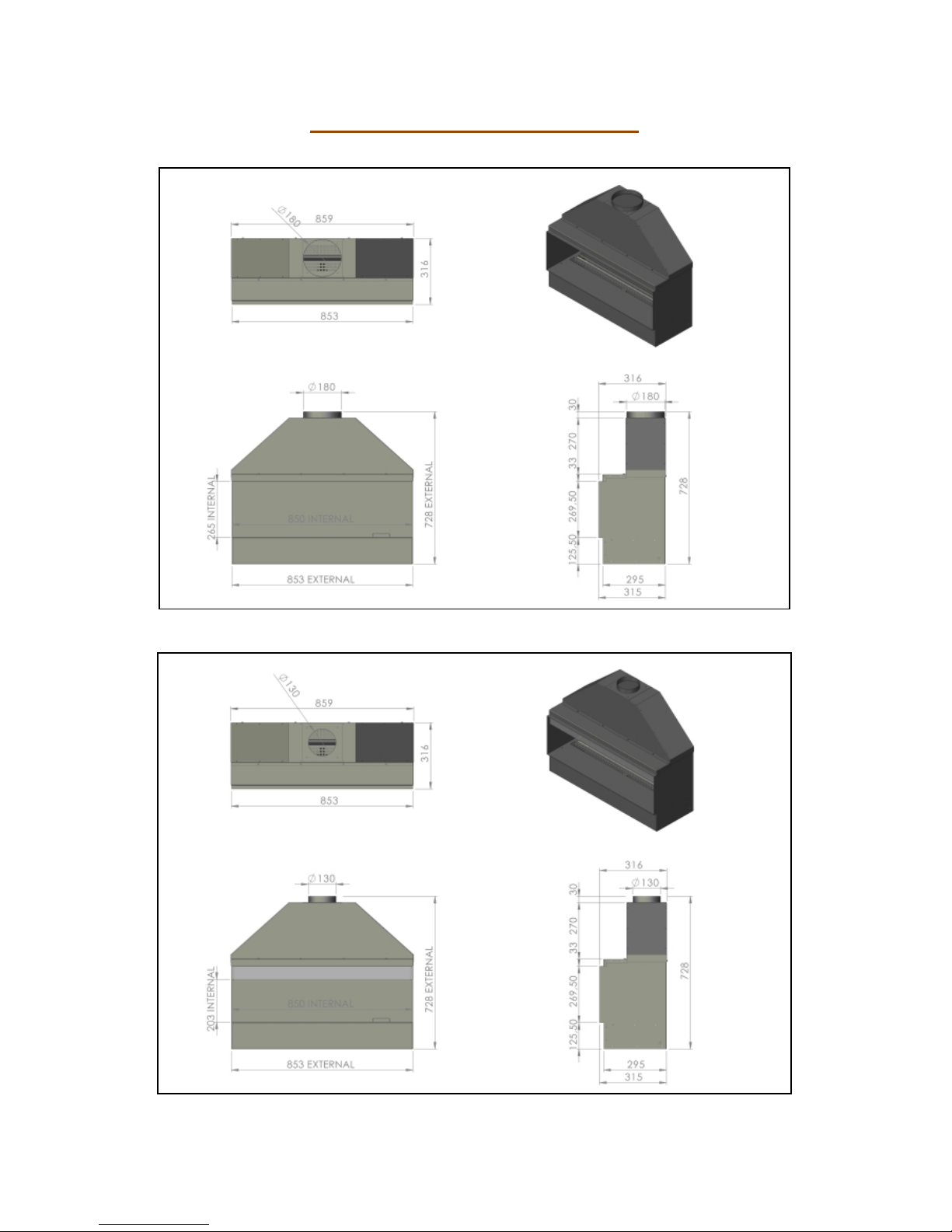
Construction Dimensions
FR-850-V
FR-850-NV
Page 8 of 54
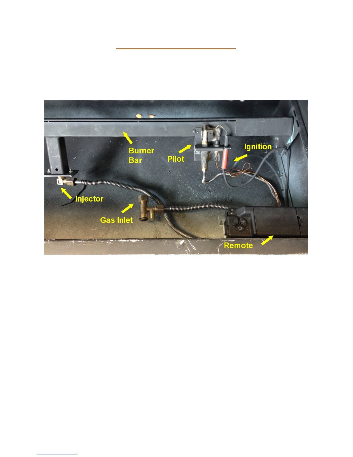
Gas Burner Construction
Use the image below to review the burner construction taking note of
the positions of the main components and the required connections.
The burner bar is pre-fitted to the enclosure. There is no reason why
this should ever be removed.
Before starting to install the appliance review the Data Plate fitted to the
appliance for the gas type and pressure requirements of the appliance. Ensure
these are correct for the property supply.
This Fire has a battery remote control system and requires only the connecti on
of an 8mm gas supply. The remote is operated by a radio frequency remote
system with handset.
All Spirit gas fires are given a 100% fu ll function test at the UK factory before
being shipped. We record over 40 test settings to ensure the fire operates
correctly and inline with the CE approval document.
There are no adjustable parts on this fire. Never remove any wires
from the black box or the remote system. All connections are required.
DO NOT DISMANTLE THE FIRE AS IT WILL INVALIDATE THE
WARRANTY.
Page 9 of 54
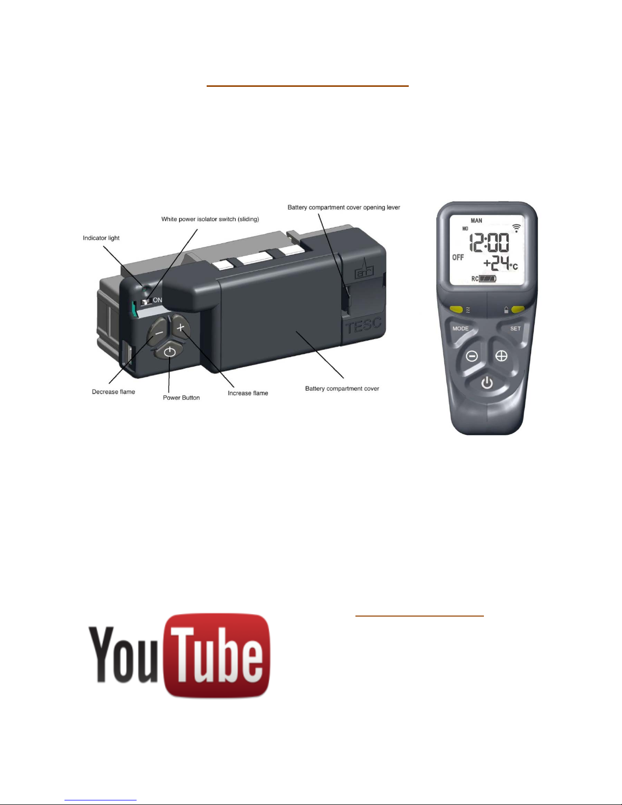
Remote Control System
Take some time to learn about the remote system fitted to this fire.
The remote system features an RF (radio frequency) handset. The handset and
the remote black box must be matched tog eth er to work corre ctl y. Read th e full
section later in this manual to ensure you understand how the remote system
works. The handset with a screen will also show any error codes which occur.
The Handset is powered by 2 x AA batteries; the Main rem ote system has 3 x
AA batteries. Always use high quality alkaline batteries to ensure a long life and
reliable performance. The batteries will last a minimum of 12 months or longer
however it is advised to ask you gas installer to replace the batteries on each
12 month service. The handset will swit ch the fire on/off and regu late the flam e
up/down. The hand set has a child safe feature to avoid accidental lighting. YOU
MUST HOLD THE HANDSET IN THE PALM OF YOUR HAND TO SWITCH ON THE
HANDSET. THIS IS INDICATED BY A GREEN LIGHT ON THE RIGHT HAND SIDE.
Please read “lighting the fire” section later in this handbook before operating
the appliance.
HELP IS AVAILABLE
There are videos on YouTube that can
be used to help you set up and use
this remote system. Search on
YouTube for “TESC GAS CONTROL”
and you will find a series of
instructional videos on how to set up
and use the hand set.

Page 10 of 54
Installation Requirements
This gas fire is intended for decorative purposes. The installation must be in
accordance with National Regulations and must be carried out by a qualified
Gas Safe Registered installer. Building work should only commence after a
thorough survey of the intended location of the impending installation has been
completed and it has been established that the unit can be installed and
operated without risk to the owner or tenants of the property or their
neighbours.
This fire must be installed and used in accordance with these instructions.
Prior to installation, ensure that the local distribution conditions (identification
of the type of gas and pressure and the adjustment of the appliance) are
compatible.
Clearances between the fire and all combustible materials must conform to
National Regulations. The builders opening or fireplace opening must be
constructed of a non- combustible material.
For some countries a non-combustible hearth must be fitted in front of the fire
in accordance with National Regulations (e.g. United Kingdom).
Before the fire is installed a flue test in accordance with National Regulations
should be carried out. Any flue damper plate or flue restrictor must be
removed or fixed permanently in the fully open position, or shall only be fitted
in accordance with National Regulations.
Where existing chimney systems are to be used in conjunction they should
have been swept and undergone thorough examination to ensure that they are
in a sound and safe condition, as well as providing an adequate draw when the
gas fire unit is in operation. A simple smoke test will reveal whether or not the
chimney is working correctly. If the chimney has been used with a solid fuel
appliance in the past it must be swept before the appliance is installed. The
unit must not be installed unless the chimney/flue length is at least the
distance indicated on page 4 (minimum flue height). The fire and flue system
should be checked regularly to ensure that it is free from obstruction.
Check gas pipe work to ensure the correct flow rate for the appliance.
There are two versions (check data plate) and the minimum flue requirements
for the fires are:
o FR-850-V – Class 1 or 180mm flue of minimum 2 meters
o FR-850-NV – Class 2 or 130mm flue of minimum 3 meters (this
model can also be used with the same flue as the FR-850-V)

Page 11 of 54
Once installed all additional gas inlet holes in the enclosure must be sealed
with metal tape to avoid flame reversal which will damage the remote.
The enclosure and flue must be seal e d i n li ne with building regulations.
It is important that the gas supply is disconnected before any old
existing surround and hearth is removed.
The gas connections must be in accordance with National Regulations. An
isolation valve, or valves, has to be fitted adjacent to the appliance which,
when closed, allow(s) the complete burner and control assembly to be
disconnected for maintenance or repair in accordance with National
Regulations. This is supplied with the fire.
The pilot light and flame sensing device fitted to this fire is also an atmosph ere
sensing devise. If for any reason any part of the pilot assembly is to be
replaced ALL the assembly including the pilot burner, thermocouple, electrode
and injector must be exchanged complete for an original manufacturer’s pilot
assembly only. This atmosphere sensing devise is not adjustable and must not
be put out of action. The pilot light shuts off both the main burner and pilot if
evacuation of the combustion products is interrupted. If the fire sh uts itself off,
do not use the fire, and have the flue and fire checked by a suitably qualified
person.
FR-850-V: This version of the gas fire requires an air vent within the room
which will provide a minimum of 100cm2 free air in accordance with National
Regulations. In some countries additional ventilation may be required
It is recommended that a guard be used for the protection of young children,
the elderly or infirm.
A qualified Gas Safe Registered engineer should service the fire at least every
12 months. This will ensure the fireplace operates safely.
After installation, the chimney should be inspected and swept regularl y to keep
the flue clear and free from debris and excessive build up of soot. The fire
needs to be covered up when work is undertaken, to ensure the unit does not
get damaged or gas outlets blocked.
Do not throw rubbish on the unit, as this will render the appliance highly
dangerous.
Due to the newness of the materials, the fire may gi ve off a slight smell for a
period of time after commissioning. This is quite normal and any odours should
disperse within a few hours of operation. Do not operate the appliance if
decorating or using scented candles. The particles will be drawn into the
fireplace and burnt causing staining and further smells.

Page 12 of 54
BEFORE STARTING TO INSTALL CHECK:
1. Gas Pipe Work: is it strong enough to supply this high power applia nc e?
Did you check the flow rates as shown on page 4?
2. Air Ventilation: First check if you are installing FR-850-V by checking the
data plate within the fire. If this model is installed you will need to install a
100cm2 air vent in the same room.
3. Chimney: is it the correct size and length for the fire you are installing?
Check the technical section on page 4. Has it been tested for leaks?
Building and Installation Work
Gas Supply
Consult the Data Plate within the appliance to ensure the correct gas type and
pressure is available within the property. Before commencing to create the fire
opening for the inglenook unit note that a gas supply is required. The gas
supply pipe should run into the installed enclosure from either the rear, left or
right hand sides, the gas supply is best run through the right side of the
enclosure. CHECK GAS SUPPLY RATE BEFORE INSTALLING (SEE PAGE 4)
The fire has an 8mm inlet via an isolation valve. The fire also includes a
pressure test point elbow to test inlet pressure. The gas pipe work should be
routed into the enclosure via the available access holes. If the gas pipe w ork is
over 1.5mtrs in length it is recommended that the pipe work is increased in
diameter from this point to 15mm, 22mm and possibly 28mm depending on the
length to the meter – see technical section for gas consumption. This will
ensure a stable gas supply.
Building Work
It is important that the gas supply is disconnected before any old existing
surround and hearth is removed. Measuring from the floor surface, the intended
location of the base of the enclosure unit is marked onto the wall. Allowances
must be made for the steel gather, if required.
The enclosure should be located centrally to the existing flue/chimney at your
desired height. If the fire is not placed central to the chimney, the flame picture
may pull incorrectly. The area indicated on the wall must be removed to house
the Fire enclosure and burner unit. In some installations it may be necessary to
install a small lintel above the opening, if so an allowance must be made to
accommodate this lintel. (The Fire does not have its own lintel). After removing
Page 13 of 54
the excess brickwork to the required height, the base of the fire op ening (which
the Fire burner and enclosure will sit upon) ha s t o be built.
To create a seal around the appliance and allow correct operation of the flue,
the original fire opening must be closed using bricks or blocks, infill the void
around the enclosure using block work or rubble. (It is advisable to install a
solid base inside the fire opening to sit the steel framework supporting the
burner unit on to.)
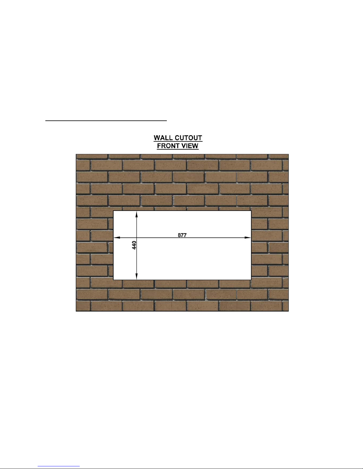
Preparing the Fireplace Opening
Above shows the minimum fireplace opening width and height.
The image shows the fireplace opening required to install the fireplace unit. The
gather can be installed by first inserting this into the fireplace opening. The fire
body is then inserted into the opening and the gather lowered down onto the
enclosure. The gather is then fixed from the inside to the enclosure using the
screws provided.
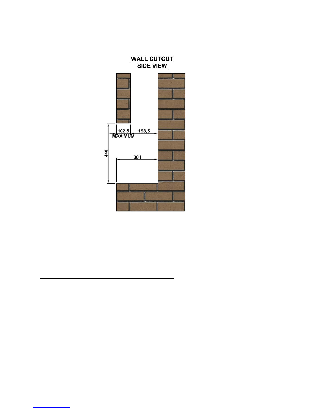
Page 14 of 54
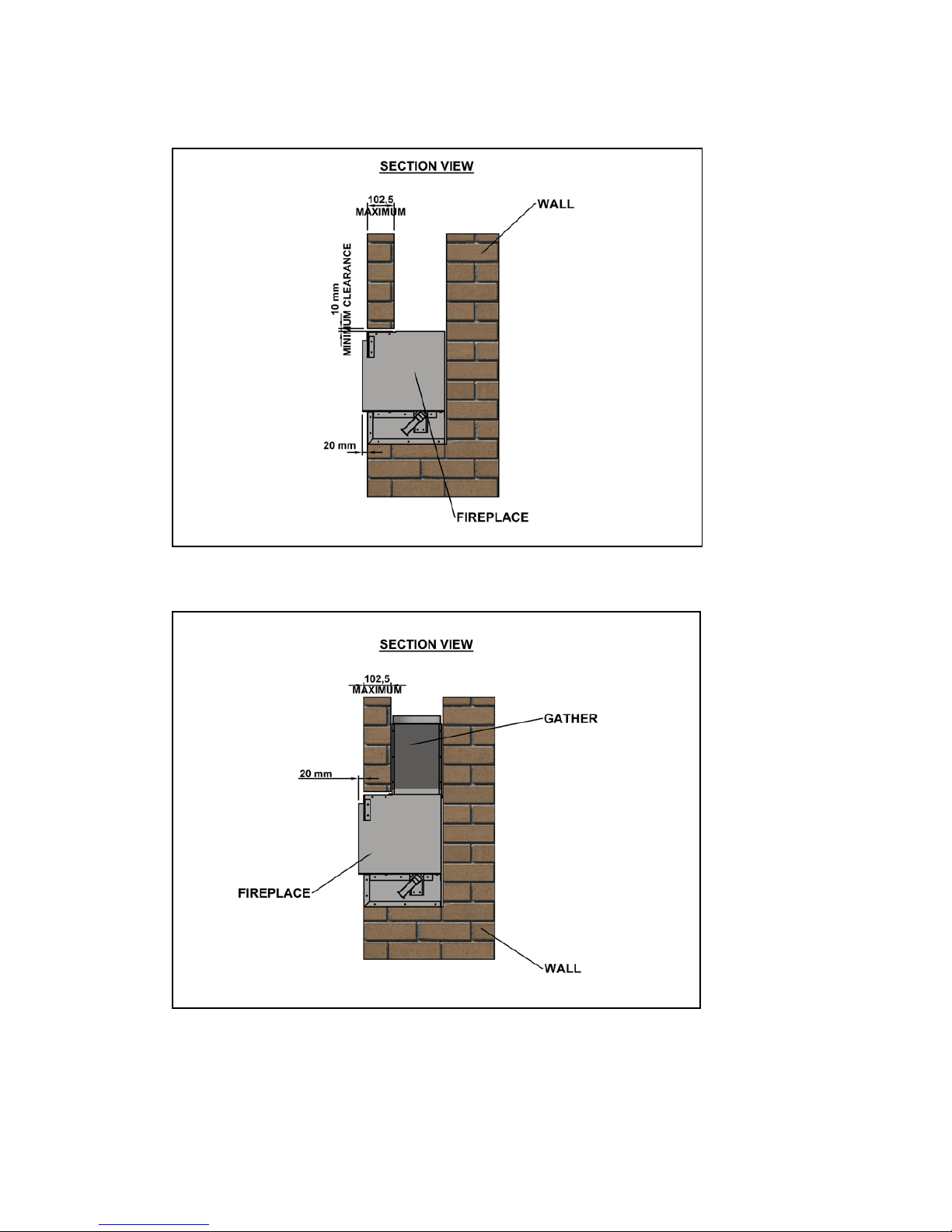
Above shows the minimum depth of the wall and the maximum lintel size when
fitting the fire with the gather. Add 20mm to this for the front face of the
finished wall (plaster board). The enclosure can be deeper however any voids
should be filled otherwise there is a r isk of “banging” when the enclosure
expands and contracts with heat.
Inserting the Fireplace into the Opening.
Once the fireplace opening has been created the appliance can be lifted into the
opening. Feed the gas pipe through the chosen hole into the lower burner area
ready for connection later. See page 18.
Without a Gather – Slide the enclosure into the opening.
With the Gather – Remove the gather from the fire and save the
screws. Insert the gather into the chimney and slide the gas appliance
into the opening. Drop the gather down onto the enclosure and secure
with the screws. Ensure the gather is sealed to the enclosure with fire
cement.
Page 15 of 54
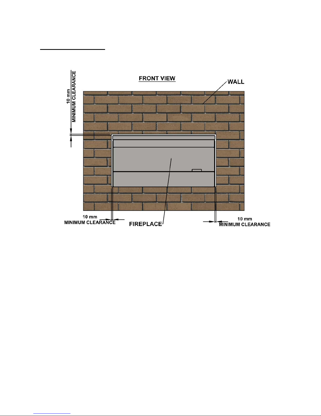
Fireplace Clearance
The fire must sit forward 20mm from the brickwork. This is for the plasterboard
that will be added later to finish the installation and create a letterbox style.
Position the enclosure in the opening so there is a minimum clearance of 10mm
on each side and 10mm at the top. This allows minor adjustment. This void
should be sealed with a suitable fire retardant material to seal the enclosure to
the opening.
Once installed in the opening the fire must be fixed down to the fireplace
opening using screws and plugs. This can be done by removing the vanity cover
and drilling through the base. Take care not to damage the connections or gas
pipes while drilling.
Page 16 of 54
Without Gather
With Gather
The gather has a spigot to allow connection to a suitable flue liner. The
diameter of the gather spigot depends on the model chosen – FR850-V
(180mm) and FR850-NV (130mm) – See data plate.
Page 17 of 54
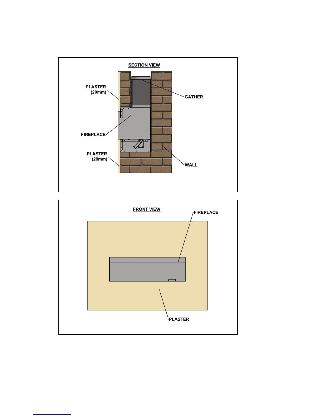
Once the fire is fixed in place the fire can be finished with plasterboard to
create the final look required.
The gas can now be connected and the fire commissioned.
 Loading...