

Spirit Fires ELLIPTICAL TRAINER, 161173795US, XE795 Owner's Manual

PLEASE CAREFULLY READ THIS ENTIRE MANUAL BEFORE
OPERATING YOUR
ELLIPTICAL
!
OWNER’S MANUAL
PLEASE CAREFULLY READ THIS ENTIRE MANUAL BEFORE
OPERATING YOUR ELLIPTICAL!
OWNER’S MANUAL
ELLIPTICAL TRAINER

2
Table Of Contents
Important Safety Instructions……………………………………………...3
Important Electrical Instructions…………………………………………..4
Important Operation Instructions………………………………………….4
Assembly Instructions…………………………………………..................6
Getting on / off your elliptical.…………………….……………………….13
Operation of Your Console……..…………………………………………15
Programmable Features…………………………………………………..18
Using A Heart Rate Transmitter…………………………………………..25
General Maintenance……………………………………………………....27
Exploded View Diagram…………………………………………….……..28
Parts List…………………………………………………………………….29
ATTENTION
This elliptical is intended for residential use only and is warranted for this application. Any
other application voids this warranty in its entirety.
XE810-AE011_1409A(SL)

3
Important Safety Instructions
When using an electrical appliance, basic precautions should always be followed, including
the following:
Read all instructions before using this appliance.
WARNING !
1. Read all instructions before using this appliance.
2. Do not operate elliptical trainer on deeply padded, plush or shag carpet. Damage to
both carpet and elliptical trainer may result.
3. Keep children away from the elliptical trainer. There are obvious pinch points and
other caution areas that can cause harm.
4. Keep hands away from all moving parts.
5. Never operate the elliptical trainer if any of the parts are damaged. If the elliptical
trainer is not working properly, call your dealer.
6. Do not operate where aerosol spray products are being used or where oxygen is
being administered. Sparks from the motor may ignite a highly gaseous
environment.
7. Never drop or insert any object into any openings.
8. Do not use outdoors.
9. Do not attempt to use your elliptical trainer for any purpose other than for the
purpose it is intended. The hand pulse sensors are not medical devices. Their
purpose is to provide you with an approximate measurement in relation to your
target heart rate. Use of a chest transmitter strap is a much more accurate
10. Method of heart rate analysis. Various factors, including the user’s movement, may
affect the curacy of heart rate readings. The pulse sensors are intended only as
exercise aids in determining heart rate trends in general.
11. Wear proper shoes. High heels, dress shoes, sandals or bare feet are not suitable
for use on your elliptical trainer. Quality athletic shoes are recommended to avoid
leg fatigue.
SAVE THESE INSTRUCTIONS - THINK SAFETCAUTION!! Please be careful when
unpacking the carton.
4
Important Electrical Instructions
WARNING!
Be aware that the generator is producing A.C. power while the elliptical trainer is being
used. Do not service the elliptical trainer while the generator is spinning; serious
electric shock could occur.
NEVER expose this elliptical trainer to rain or moisture. This product is NOT designed for
use outdoors, near a pool or spa, or in any other high humidity environment. The
operating temperature specification is 40 to 120 degrees Fahrenheit, and humidity is
95% non-condensing (no water drops forming on surfaces).
I
mportant Operation Instructions
NEVER operate this elliptical trainer without reading and completely understanding the
results of any operational change you request from the computer.
Understand that changes in resistance do not occur immediately. Set your desired
resistance level on the computer console and release the adjustment key. The computer
will obey the command gradually.
Use caution while participating in other activities while pedaling on your elliptical trainer;
such as watching television, reading, etc. These distractions may cause you to lose
balance which may result in serious injury.
Do not use excessive pressure on console control keys. They are precision set to
function properly with little finger pressure.
■
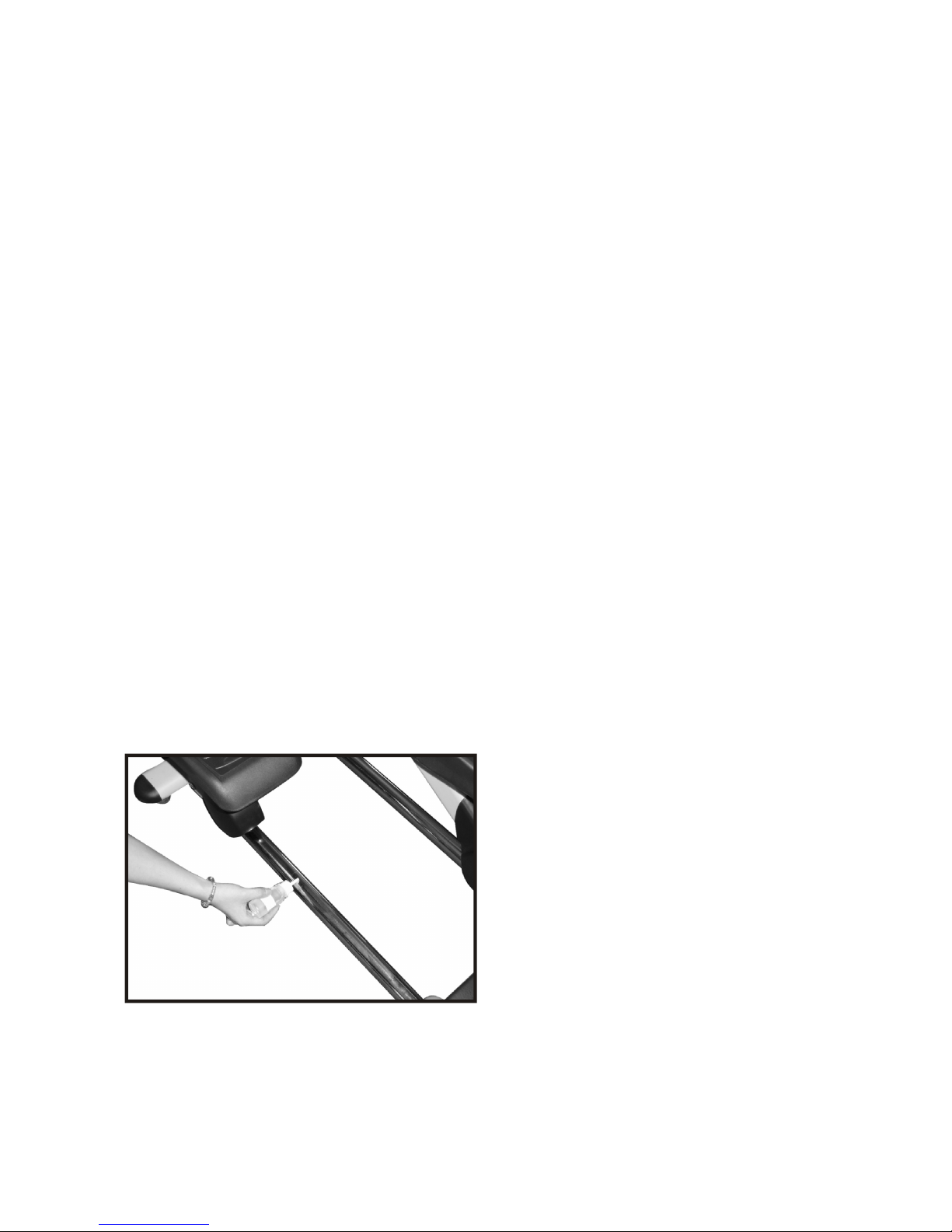
Elliptical Lubrication
1. Pour 2c.c of the lubricant under the middle of the rail. You must lubricate the rails every
three months.
2. If you feel the exercise is not smooth or you hear noise during your exercise, lubricate the
middle rail with 2 c.c.of the lubricant.
Transportation
The elliptical is equipped with transport wheels, which are engaged when the rear of the
elliptical is lifted.

5
Assembly Instructions
PRE-ASSEMBLY
1. Using a razor knife (Box Cutter), cut the banding straps that wrap around the carton.
Reach under the bottom edge of the carton and pull it away from the cardboard
underneath, separating the staples that join the two together. Lift the box over the unit
and unpack.
2. Carefully remove all parts from carton and inspect for any damage or missing parts. If
damaged parts are found, or parts are missing, contact your dealer immediately.
3. Locate the hardware package. The hardware is separated into four steps. Remove the
tools first. Remove the hardware for each step as needed to avoid confusion. The
numbers in the instructions that are in parenthesis (#) are the item number from the
assembly drawing for reference.
Assembly Tools
#94. Phillips Head Screw driver (1 pc)
#93. 13/14mm Wrench (1 pc)
#98. 12/14mm Wrench (1 pc)
#95. 8mm L Allen Wrench (1 pc)
#97. 5mm L Allen Wrench (1 pc)
6
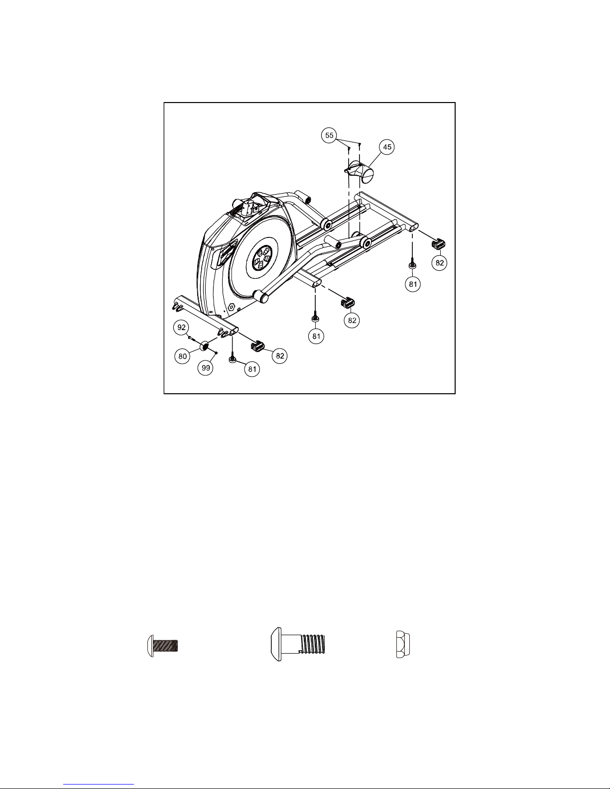
STEP 1
1. Gather HARDWARE FOR STEP 1.
2. Tilt the elliptical trainer to one side (you may want to place a piece of Styrofoam or a block
under the unit for support). Install the 3 LEVELERS (81) to the underside of the unit.
Repeat this lever assembly on opposite side of the unit.
3. Press the 6 END CAPS (82) into the oval stabilizer tubes.
4. Attach the TRANSPORT WHEELS (80) to each bracket with 2 BOLTS (92) and 2 NUTS
(99). Partially tighten with the 13/14mm WRENCH and 5mm L WRENCH. Over tightening
the hardware will prevent the wheels from rotating.
5. Attach the SLIDE WHEEL COVERS (45) with 4 SCREWS (55). Tighten with the screw
driver.
NOTE: When assembly is complete, the transport wheels can be engaged by lifting the rear
of the elliptical trainer.
HARDWARE
#55.
M5 × 10m/m
Phillips Head Screw
(4pcs)
#99.
5/16"
Nyloc Nut
(2 pcs)
#92.
5/16" ×1-3/4" Button
Head Socket Bolt
(2 pcs)
7
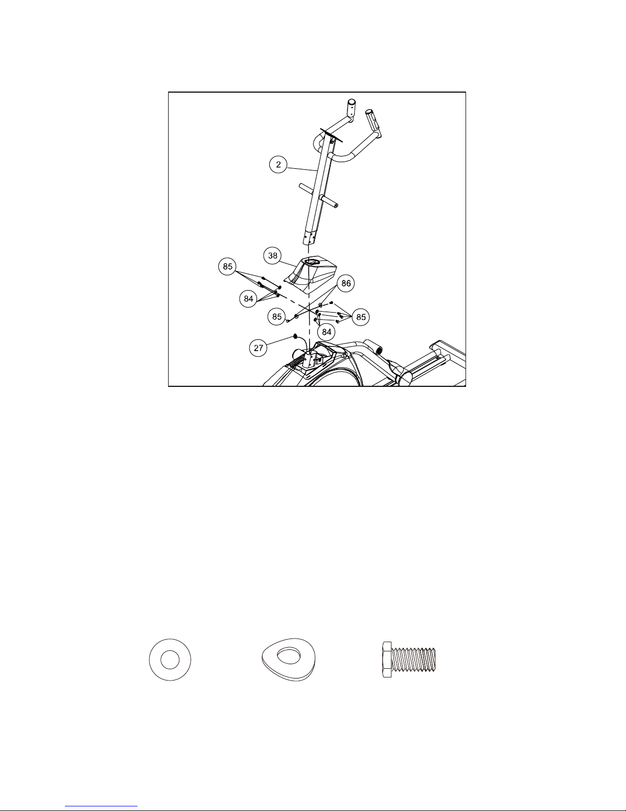
STEP 2
1. Gather HARDWARE FOR STEP 2.
2. Unwind the COMPUTER CABLE (27) from the frame bracket and run it through the
CONSOLE MAST COVER (38). Use the twist tie at the bottom of the CONSOLE MAST
TUBE (2) and wrap around the computer cable. Feed the computer cable up through the
MAST (2) and pull through the top of the mast.
3. Insert the bottom of the CONSOLE MAST (2) into the frame bracket. Be sure not to pinch
the computer cable between the mast and the frame during this step.
4. Slide the CONSOLE MAST COVER (38) up the CONSOLE MAST (2) and secure the
mast to the frame with 3 BOLTS (85) and 3 FLAT WASHERS (84) to each side of the mast.
Secure with a BOLT (85) and CURVED WASHER (86) to both the front and back of the
mast. Tighten all bolts with the 13/14 WRENCH.
5. Snap the CONSOLE MAST COVER (38) in place over the frame covers.
HARDWARE
#86.
5/16" × 23 × 1.5T
Curved Washer
(2 pcs)
#84.
5/16" × 18 × 1.5T
Flat Washer
(6 pcs)
#85.
M8x15mm
Hex Head Bolt
(8 pcs)
8
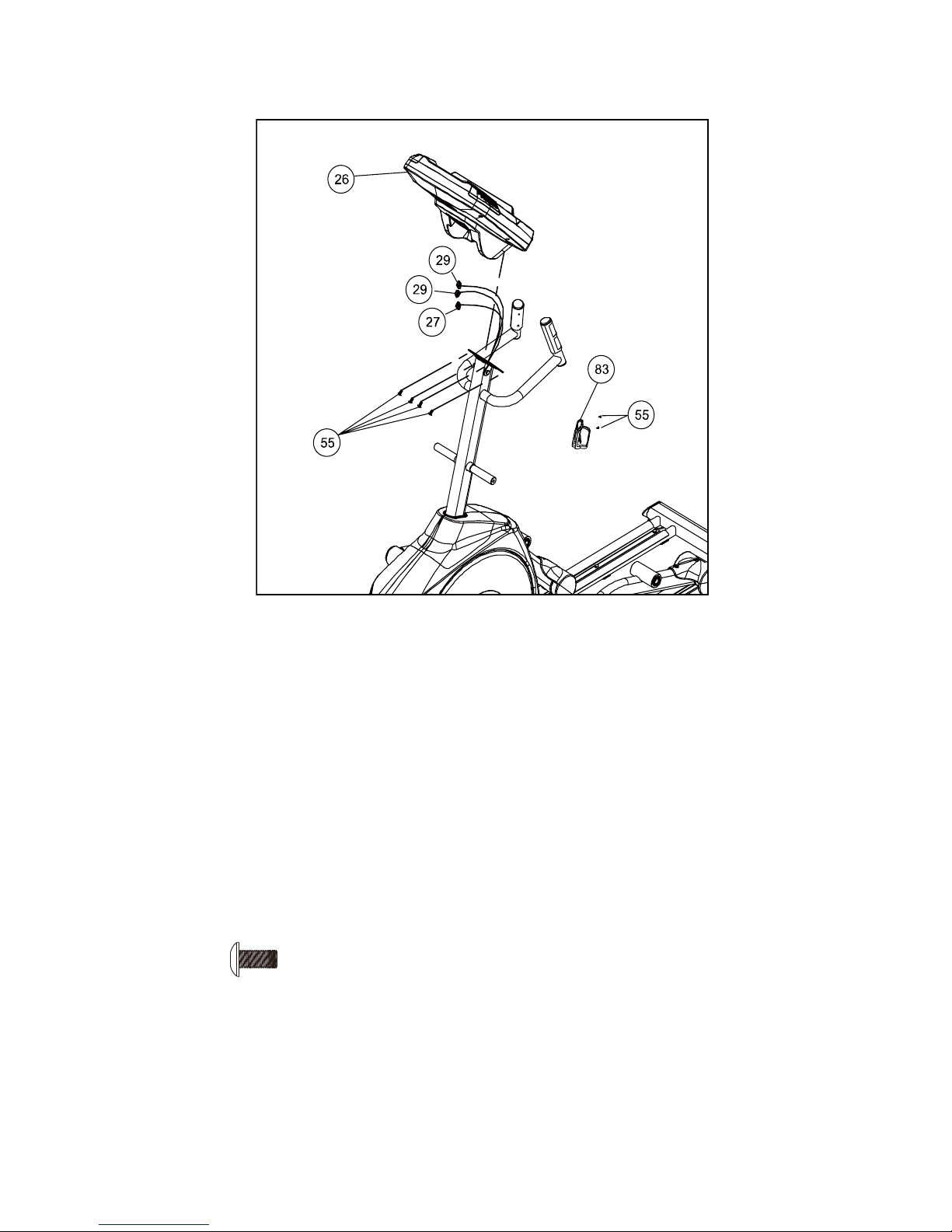
STEP 3
1. Gather HARDWARE FOR STEP 3.
2. Plug the COMPUTER CABLE (27) and the HANDPULSE W/ CABLES (29) into the
backside of the console.
3. Secure the CONSOLE (26) to the CONSOLE MAST with 4 SCREWS (55). Tighten with
the SCREW DRIVER.
4. Secure the WATER BOTTLE HOLDER (83) to the CONSOLE MAST with 2 SCREWS
(55).Tighten with the SCREW DRIVER
HARDWARE
#55.
M5 × 10m/m
Phillips Head Screw
(6pcs)
9
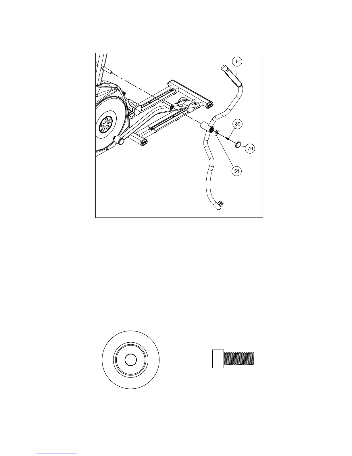
STEP 4
1. Gather HARDWARE FOR STEP 4.
2. Remove the foam from the console mast axles and the plastic ties from the swing arm
tube.
3. The swing arms will be labeled “L” for left and “R” for right. Slide the LEFT SWING ARM (5)
onto the left console mast axle. The swing arms have been preassembled at the factory to
assure a proper fit. The fit will be snug. Please do not force the arm on the axle or use a
hammer, as damage to the bearings could occur.
4. Secure the swing arm to the mast with the BUSHING WASHER (51) and the SOCKET
HEAD CAP BOLT (89). Tighten with the 8mm L WRENCH.
5. Snap on the decorative BUSHING ROUND END CAP (79).
6. Repeat these steps on the right side.
HARDWARE
#51
.
M10
Bushing Washer
(2 pcs)
#89.
M10 × 20m/m
Socket Head Cap Bolt
(2 pcs)
10
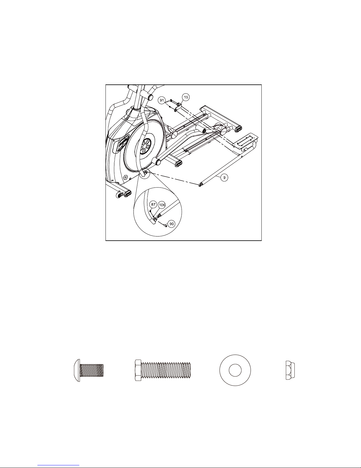
STEP 5
1. Gather HARDWARE FOR STEP 5.
2. Take the LEFT CONNECTING ARM (9) and slide the axle through the rotation tube on the
left pedal arm.
3. Secure the LEFT CONNECTION ARM (9) in place with the 5-WAY PIPE FIXING PLATE
(15) and 3 KEY HEAD SOCKET BOLTS (91).Tighten with the 5mm L WRENCH.
4. Line up the socket joint at the end of the pedal arm to the bracket on the bottom of the
swing arm. Secure together with the BOLT (90) WASHER (106) and NUT (87). Tighten
with the 13/14 WRENCH and the 12/14 WRENCH.
5. Repeat these steps on the right side.
HARDWARE
#106.
5/16" × 20 × 1.5T
Flat Washer (2 pcs)
#90.
5/16" × 1- 1/4"
Hex Head Bolt (2 pcs)
#87.
5/16" × 9T
Nyloc Nut (2 pcs)
#91.
M8 ×15m/m
Button Head Socket
Bolt (6 pcs)

11
STEP 6
1. Gather HARDWARE FOR STEP 6.
2. Install the FOOT PEDALS (L 47) (R 48) with 8 PHILIPS HEAD SCREWS (55). Tighten
with the SCREW DRIVER.
HARDWARE
#55.
M5 × 10m/m
Phillips Head Screw
(8pcs)
 Loading...