

Spirit FOLIO SX mixer User Manual

PAGE 9
PAGE 15
PAGE 15
PAGE 14
PAGE 15
PAGE 9
PAGE 9/12
PAGE 9
PAGE 10
PAGE 10
PAGE 10
PAGE 11
Page 1
PAGE 14
PAGE 14
PAGE 15
PAGE 11
Page 2

INTRODUCTION
Thank you for purchasing a SPIRIT FOLIO SX mixer, brought to you with pride by the SPIRIT team of Andy, Colin,
Chris, James, Simon, Mukesh, Graham, Martin, Paul, Matt and Peter, with the support of many others - we hope you will
have as much fun using it!
Owning a SPIRIT console brings you the expertise and support of one of the industrys leading manufacturers and the
results of over 23 years experience supporting some of the biggest names in the business.
Built to the highest standards using quality components and new surface mount technology, FOLIO SX is designed to
be as easy to use as possible, but some time spent NOW, looking through this manual and getting to know your new
mixer will give you lots of helpful tips and confidence, away from the pressures of a live session. Dont be afraid to experiment to find out how each control affects the sound - this will only extend your creativity and help you to get the best
from your mixer.
Installation and Safety Precautions
Installing the Mixer
orrect connection and positioning of your mixer is important for successful and trouble-free operation. The following
C
sections are intended to give guidance with cabling, connections and configuration of your mixer.
o Choose the mains supply for the sound system with care, and do not share sockets or earthing with lighting dimmers.
o Position the mixer where the sound can be heard clearly.
o Run audio cables separately from dimmer wiring, using balanced lines wherever possible. If necessary, cross audio and
lighting cables at right angles to minimise the possibility of interference. Keep unbalanced cabling as short as possible.
o Check your cables regularly and label each end for easy identification.
SAFETY PRECAUTIONS
For your own safety and to avoid invalidation of the warranty please
read this section carefully.
The FOLIO SX mixer must only be connected through the Power Supply supplied.
The wires in the mains lead are coloured in accordance with the following code:
Earth: Green and Yellow (Green/Yellow - US)
Neutral: Blue (White - US)
Live: Brown (Black - US)
As the colours of the wires in the mains lead may not correspond with the coloured markings identifying the terminals in
your plug, proceed as follows:
The wire which is coloured Green and Yellow must be connected to the terminal in the plug which is marked with the
letter E or by the earth symbol.
The wire which is coloured Blue must be connected to the terminal in the plug which is marked with the letter N.
The wire which is coloured Brown must be connected to the terminal in the plug which is marked with the letter L.
Ensure that these colour codings are followed carefully in the event of the plug being changed.
To avoid the risk of fire, replace the mains fuse only with the correct value fuse, as
indicated on the power supply.
Page 3
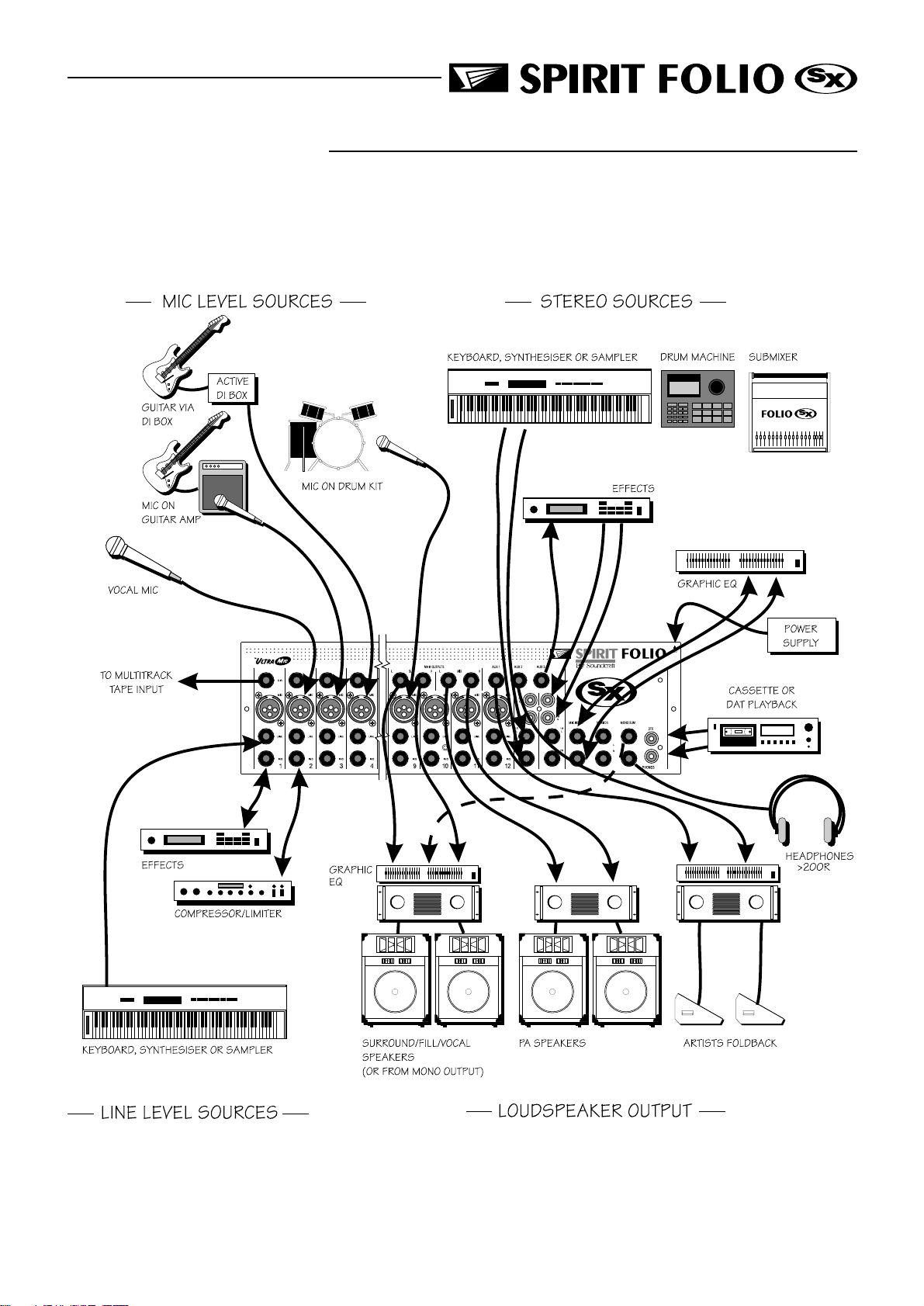
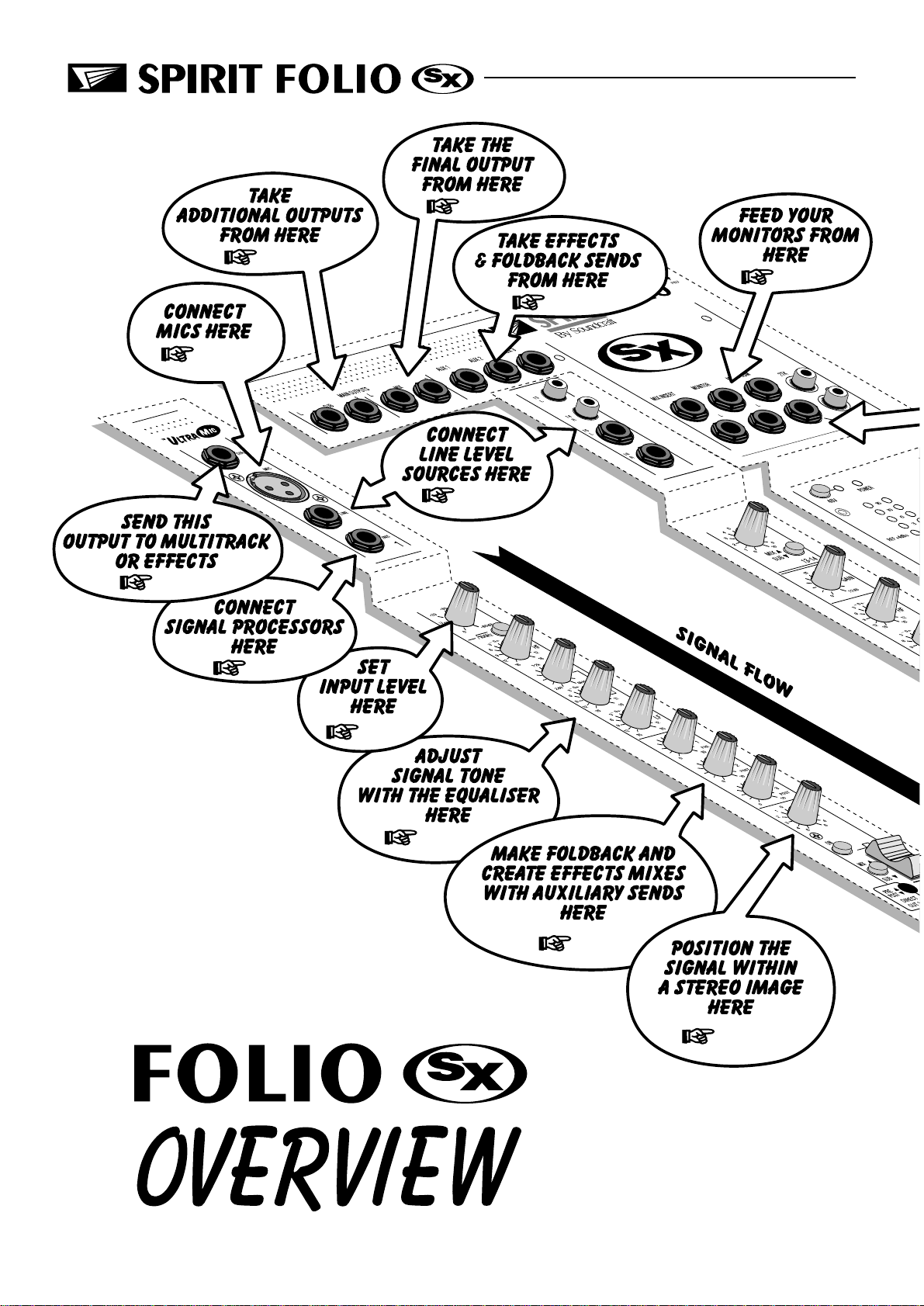
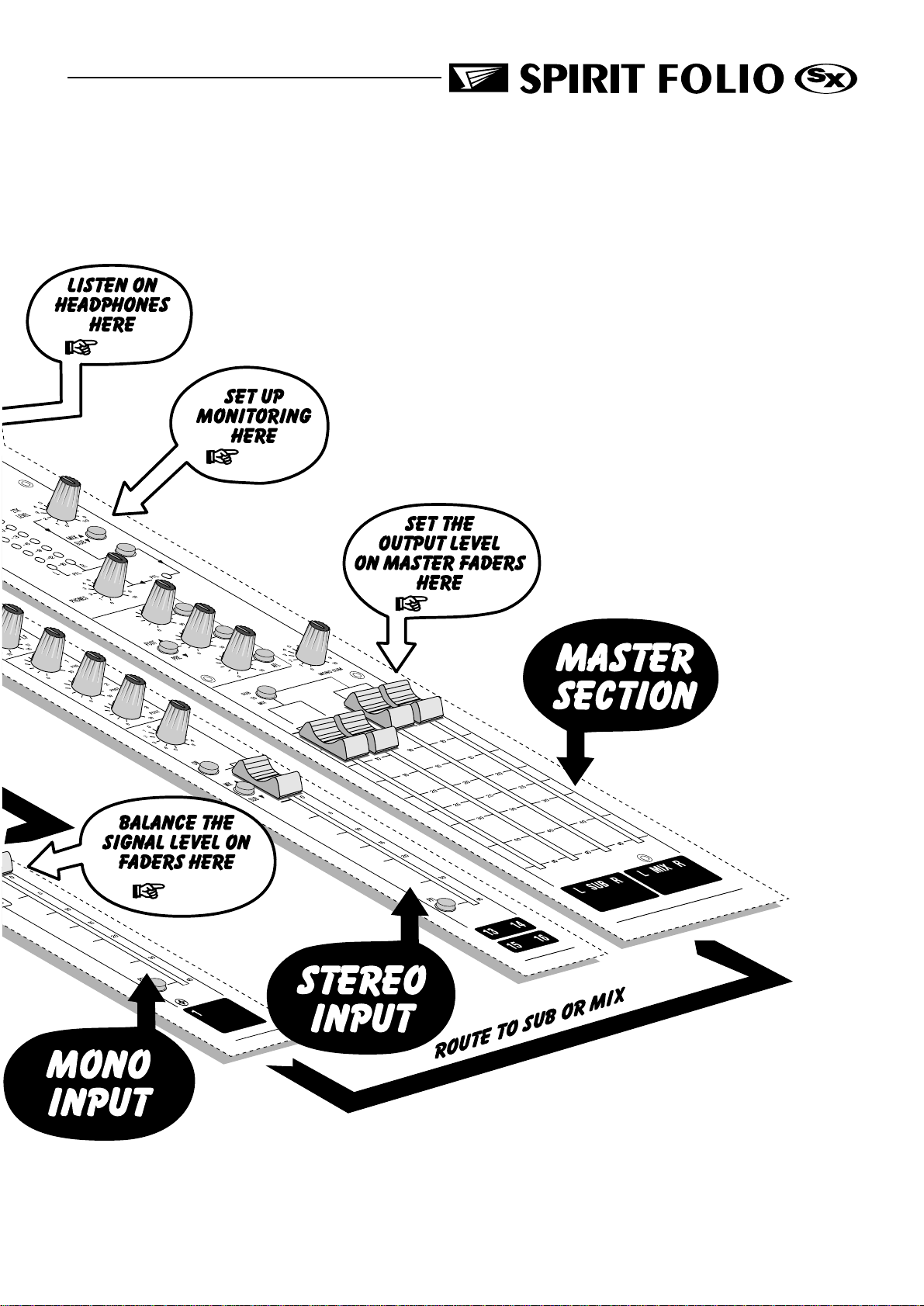
CONNECTING IT UP
Page 4
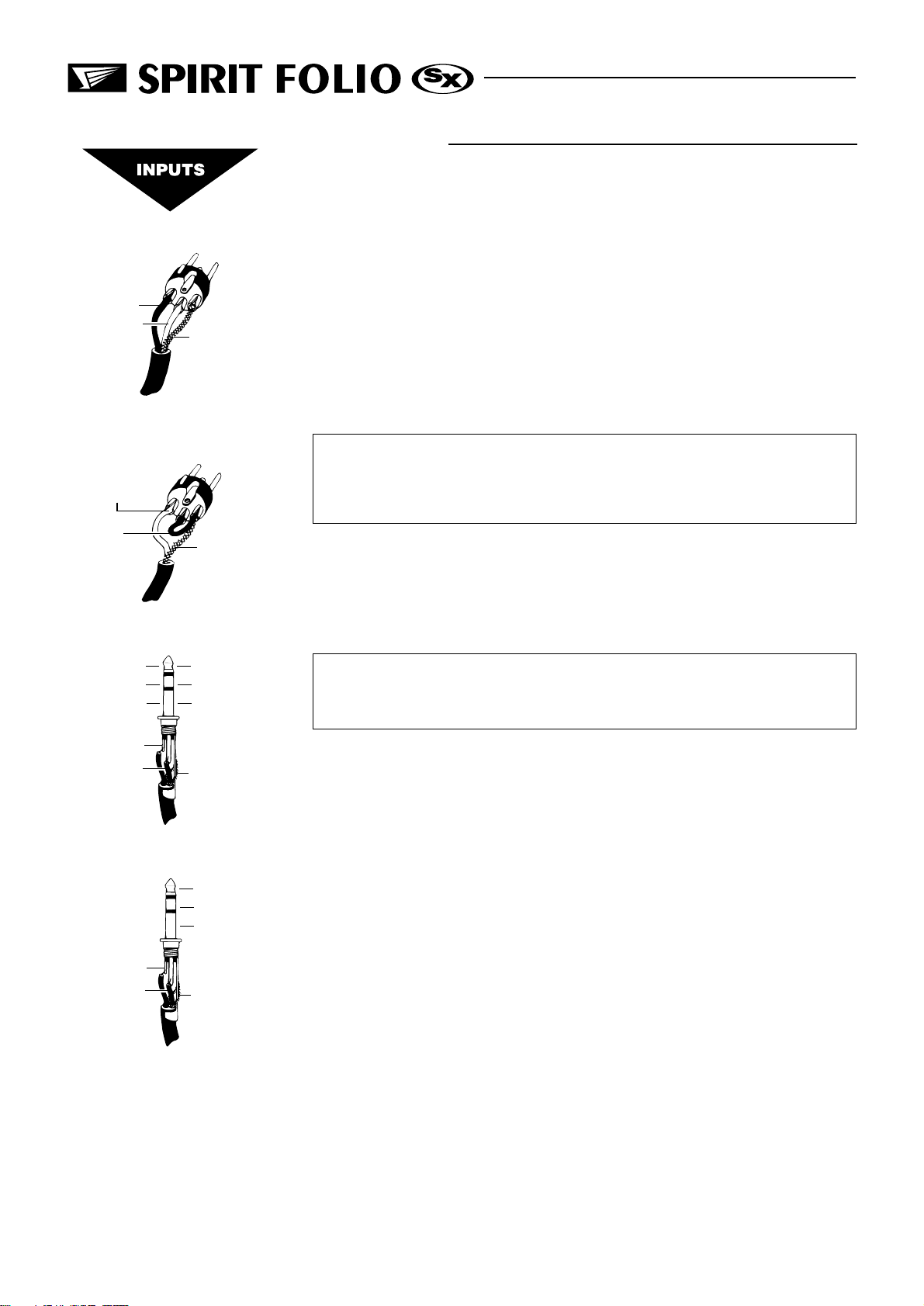
WIRING UP
Please refer to pages 27/28 for additional wiring details.
2. Hot(+ve)
3. Cold(-ve)
2. Hot(+ve)
Link 3
to 1
Balanced
3 pole Jack
Hot (+ve)
Cold (-ve)
Gnd/Screen
Balanced Mic
XLR
1. Screen
Unbalanced Mic
XLR
1. Screen
Unbalanced
3 pole Jack
Signal
Gnd/Screen
Gnd/Screen
MIC INPUT
The mic input accepts XLR-type connectors and is designed to suit a wide range of
BALANCED or UNBALANCED low-level signals, whether from delicate vocals
requiring the best low-noise performance or close-miked drum kits needing maximum
headroom. Professional dynamic, condenser or ribbon mics are best because these
will be LOW IMPEDANCE. While you can use low-cost HIGH IMPEDANCE mics,
you do not get the same degree of immunity to interference on the microphone cable
and as a result the level of background noise may be higher. If you turn the PHANTOM POWER on, the socket provides a suitable powering voltage for professional
condenser mics.
DO NOT use UNBALANCED sources with the phantom power switched on.
The voltage on pins 2 & 3 of the XLR connector may cause serious damage.
BALANCED dynamic mics may normally be used with phantom power
switched on (contact your microphone manufacturer for guidance).
The input level is set using the input SENS knob.
The LINE input offers the same gain range as the MIC input, but at a higher input
impedance. This is suitable for most line level sources, and provides the gain needed
for lower level keyboards and high impedance microphones.
WARNING - Start with the input SENS knob turned fully anticlockwise when
plugging high level sources into the LINE input to avoid overloading the
input channel or giving you a very loud surprise!
Tip
Ring
Tip
Ring
Inserts
Sleeve
Signal Send
Signal Return
Gnd/Screen
Sleeve
LINE INPUT
Accepts 3-pole `A gauge jacks, or 2-pole mono jacks which will automatically
ground the cold input. Use this input for sources other than mics, such as keyboards,
drum machines, synths, tape machines or guitars. The input is BALANCED for low
noise and immunity from interference, but you can use UNBALANCED sources by
wiring up the jacks as shown, although you should then keep cable lengths as short as
possible to minimise interference pick-up on the cable. Note that the ring must be
grounded if the source is unbalanced. Set the input level using the SENS knob, starting
with the knob turned fully anticlockwise. Unplug any MIC connection when using the
LINE input.
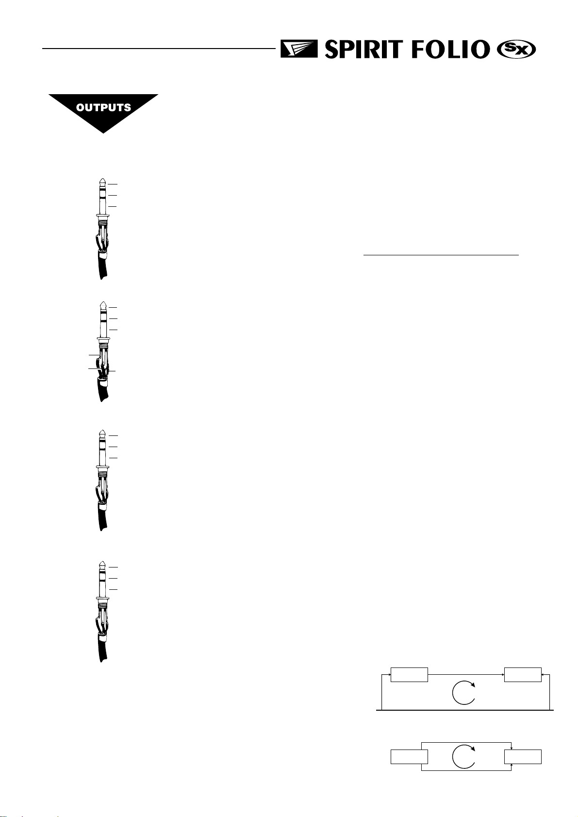
INSERT POINT
The unbalanced, pre-EQ insert point is a break in the channel signal path, allowing
limiters, compressors, special EQ or other signal processing units to be added in the
signal path. The Insert is a 3-pole A gauge jack socket which is normally bypassed.
When a jack is inserted, the signal path is broken, just before the EQ section.
The signal from the channel appears on the TIP of the plug and is returned on the
RING, with the sleeve as a common ground.
The Send may be tapped off as an alternative pre-fade, pre-EQ direct output if
required, using a lead with tip and ring shorted together so that the signal path is not
interrupted.
Page 5

Mix & Sub Outputs
Aux Outputs
Mono Output
Signal +
Signal Screen
STEREO INPUTS 13/14 & 17/18
These accept RCA phono jacks to allow easy connection to hi-fi equipment or DAT
players. The input is unbalanced, and ideal for pre-show music sources or signals that do
not require any EQ or effects.
STEREO INPUTS 15/16 & 19/20
These accept 3-pole `A gauge jacks, or 2-pole mono jacks which will automatically
ground the cold input. Use these inputs for sources such as keyboards, drum machines,
synths, tape machines or as returns from processing units. The input is BALANCED for
low noise and immunity from interference, but you can use UNBALANCED sources by
wiring up the jacks as shown, although you should then keep cable lengths as short as
possible to minimise interference pick-up on the cable. Note that the ring must be
grounded if the source is unbalanced.
Mono sources can be fed to both paths by plugging into the Left jack only.
Mix Inserts
Tip
Ring
Headphones
Monitor Outputs
Direct Outputs
Signal Send
Signal Return
Gnd/Screen
Sleeve
Left Signal
Right Signal
Ground
Signal
Ground
Ground
MIX INSERTS
The unbalanced, pre-fade Mix insert point is a break in the output signal path to allow
the connection of, for example, a compressor/limiter or graphic equaliser. The Insert is
a 3-pole A gauge jack socket which is normally bypassed. When a jack is inserted, the
signal path is broken, just before the mix fader.
The mix signal appears on the TIP of the plug and is returned on the RING. A Y
lead may be required to connect to equipment with separate send and return jacks as
shown below:
Insert Point
Signal Send
Screen
Signal Return
Note: If XLRs are used, join Pins 1 & 3
Send to External Device
and connect to cable screen.
Connect Pin 2 to signal.
Return from External Device
MIX & SUB OUTPUTS
The MIX and SUB outputs are on 3-pole 3-pole A gauge jack sockets, wired as
shown, and incorporate impedance balancing, allowing long cable runs to balanced amplifiers and other equipment.
From FOLIO SX
Impedance Balanced
Output
Signal
(a) Balanced Connection
To External Device
From FOLIO SX
Impedance Balanced
Output
Screen
Signal
Screen
Page 6
Signal Ground
(b) Unbalanced Connection
Signal Ground
Experience has shown that sometimes it is better
not to connect screen at external device end.
To External Device
Mix & Sub Outputs
Aux Outputs
Mono Output
Signal +
Signal Screen
Mix Inserts
Signal Send
Signal Return
Gnd/Screen
Tip
Ring
Sleeve
AUX OUTPUTS
The Aux outputs are on 3-pole A gauge jack sockets, wired as shown on the left,
and incorporate impedance balancing, allowing long cable runs to balanced amplifiers and
other equipment.
CHANNEL DIRECT OUTPUTS
The Direct outputs are on 3-pole A gauge jack sockets, wired as shown on the left,
and are unbalanced.
HEADPHONES
The PHONES output is a 3-pole A gauge jack, wired as a stereo output as shown,
suitable for headphones of 200W or greater. 8W headphones are not recommended.
Polarity (PHASE)
You will probably be familiar with the concept of polarity in electrical signals and this
is of particular importance to balanced audio signals. Just as a balanced signal is highly
effective at cancelling out unwanted interference, so two microphones picking up the
same signal can cancel out, or cause serious degradation of the signal if one of the cables
has the +ve and -ve wires reversed. This phase reversal can be a real problem when
microphones are close together and you should therefore take care always to connect
pins correctly when wiring audio cables.
Headphones
Left Signal
Right Signal
Ground
Monitor Outputs
Direct Outputs
Signal
Ground
Ground
Grounding and Shielding
For optimum performance use balanced connections where possible and ensure that
all signals are referenced to a solid, noise-free earthing point and that all signal cables
have their screens connected to ground. In some unusual circumstances, to avoid earth
`loops ensure that all cable screens and other signal earths are connected to ground
only at their source and not at both ends.
If the use of unbalanced connections is unavoidable, you can mimimise noise by following these wiring guidelines:
l On INPUTS, unbalance at the source and use a twin, screened cable as though it
were balanced.
l On OUTPUTS, connect the signal to the +ve output pin, and the ground of the out-
put device to -ve. If a twin screened cable is used, connect the screen only at the
mixer end.
l Avoid running audio cables or placing audio equipment, close to thyristor dimmer
units or power cables.
l Noise immunity is improved significantly by the use of low impedance sources, such
as good quality professional microphones or the outputs from most modern audio
equipment. Avoid cheaper high imped-
ance microphones, which may suffer
from interference over long cable runs,
even with well-made cables.
Example 1
Mixer
Audio (with ground connected)
Earth Loop
Amplifier
SupplySupply
l Grounding and shielding is still seen as a
black art, and the suggestions above are
only guidelines. If your system still hums,
an earth loop is the most likely cause.
Two examples of how an earth loop can
occur are shown on the right
Page 7
Example 2
Left Signal (with ground connected)
Mixer
Right Signal (with ground connected)
Mains Earth
Earth Loop
Amplifier
Fault Finding Guide
Repairing a sound mixing console requires specialist skills, but basic Fault Finding is
within the scope of any user if a few basic rules are followed.
l Get to know the Block Diagram of your console (see page 29).
l Get to know what each component in the system is supposed to do.
l Learn where to look for common trouble spots.
The Block Diagram is a representative sketch of all the components of the console,
showing how they connect together and how the signal flows through the system. Once
you have become familiar with the various component blocks you will find the Block
Diagram quite easy to follow and you will have gained a valuable understanding of the
internal structure of the console.
Each Component has a specific function and only by getting to know what each part
is supposed to do will you be able to tell if there is a genuine fault! Many `faults are the
result of incorrect connection or control settings which may have been overlooked.
Basic Troubleshooting is a process of applying logical thought to the signal path
through the console and tracking down the problem by elimination.
l Swap input connections to check that the source is really present. Check both Mic
and Line inputs.
l Eliminate sections of the channel by using the insert point to re-route the signal to
other inputs that are known to be working.
l Route channels to different outputs or to auxiliary sends to identify problems on the
Master section.
l Compare a suspect channel with an adjacent channel which has been set up
identically. Use PFL and AFL to monitor the signal in each section.
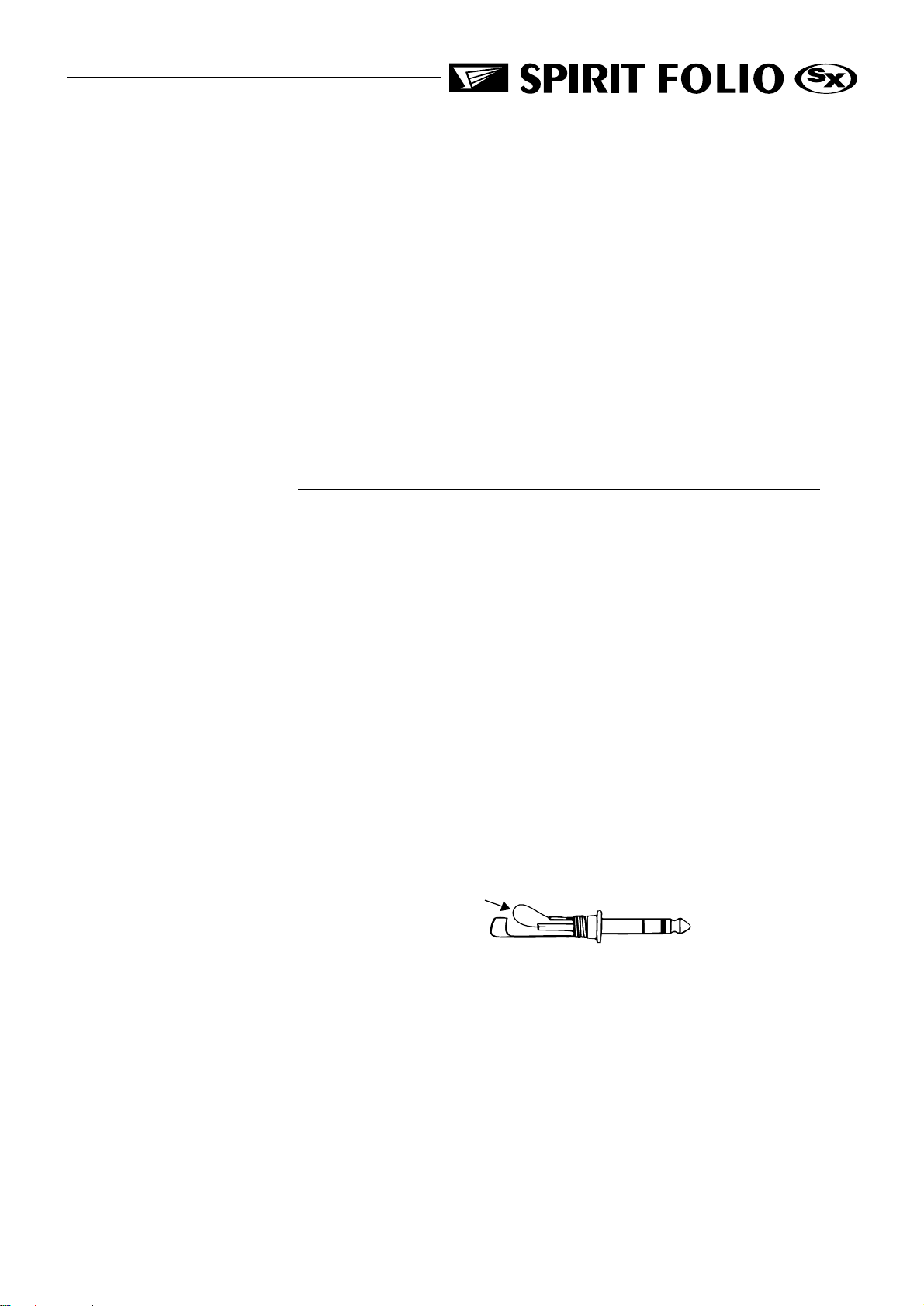
Insert contact problems may be checked by using a dummy jack with tip and ring
shorted together as shown below. If the signal appears when the jack is inserted it
shows that there is a problem with the normalling contacts on the jack socket, caused by
wear or damage, or often just dirt or dust. Keep a few in your gig tool box.
Wire Link
Dummy Insert Bypass Jack
Page 8
GETTING TO KNOW YOUR CONSOLE
1
Mono Input Channel
2
3
4
5
6
7
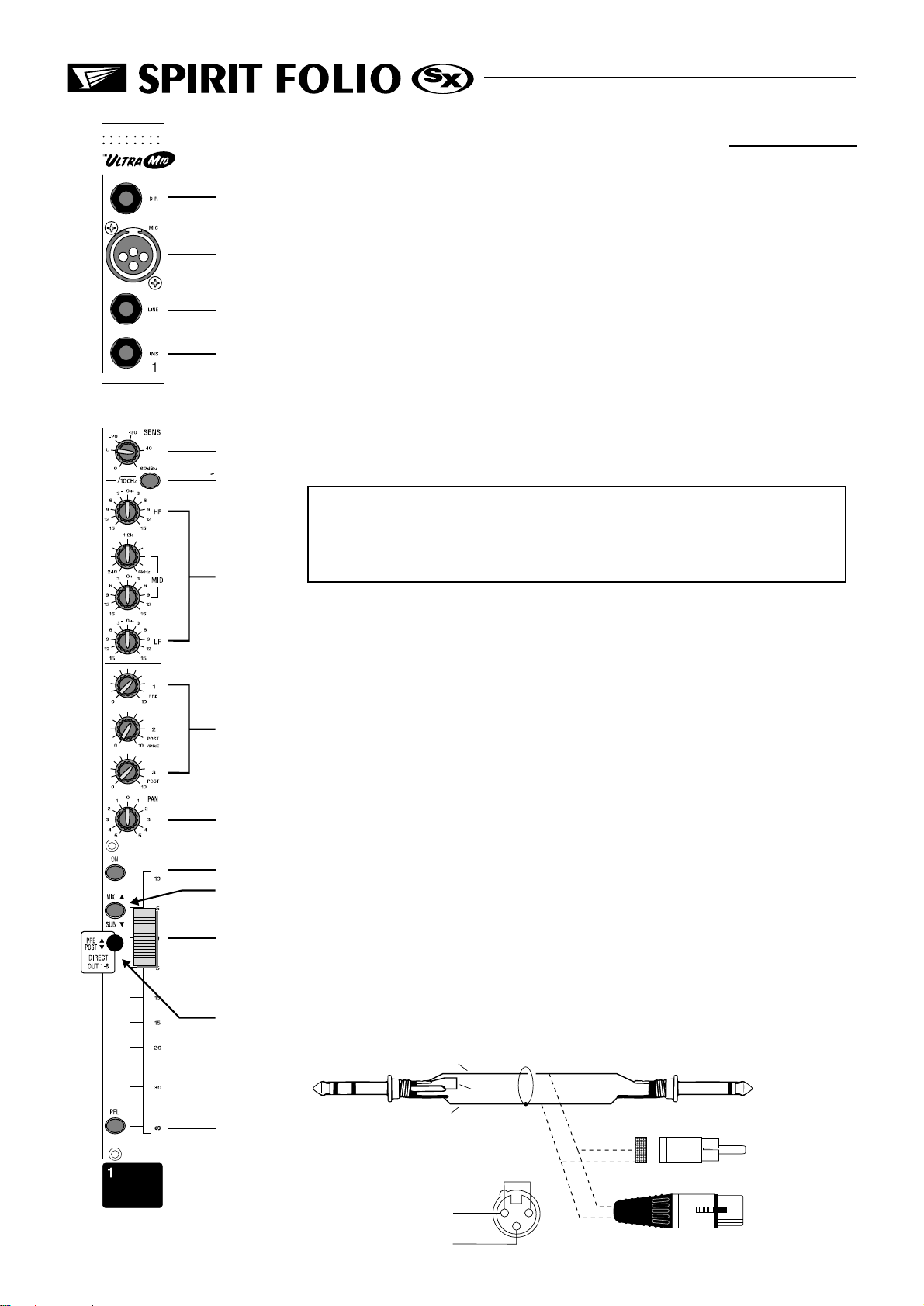
1 DIRECT OUTPUT
The first eight channels have a dedicated Direct Output which allows direct connection to external devices, for example to feed Tape Machines or effects units. See the
Advanced Features section on page 18 for a full explanation of these outputs.
2 MIC INPUT
The mic input accepts XLR-type connectors and is designed to suit a wide range of
BALANCED or UNBALANCED signals. Professional dynamic, condenser or ribbon
mics are best because these will be LOW IMPEDANCE. You can use low-cost HIGH
IMPEDANCE mics, but the level of background noise will be higher. If you turn the
PHANTOM POWER on (top right-hand side of the mixer) the socket provides a suitable
powering voltage for professional condenser mics.
ONLY connect condenser microphones with the +48V
powering OFF, and ONLY turn the +48V powering on or off
with all output faders DOWN, to prevent damage to the
mixer or external devices.
TAKE CARE when using unbalanced sources, which may be damaged by the phantom power voltage on pins 2 & 3 of the XLR connector.
Unplug any mics if you want to use the LINE Input. The input level is set using the
SENS knob.
10
11
12
13
14
8
3 LINE INPUT
Accepts 3-pole `A gauge (TRS) jacks. Use this input for sources other than mics,
such as keyboards, drum machines, synths, tape machines or guitars. The input is BALANCED for low noise and top quality from professional equipment, but you can use
9
UNBALANCED sources by wiring up the jacks as shown below, although you should
then keep cable lengths as short as possible. Unplug anything in the MIC input if you
want to use this socket. Set the input level using the SENS knob.
4 INSERT POINT (ALTERNATIVE DIRECT SEND)
The unbalanced, pre-EQ insert point is a break in the channel signal path, allowing
limiters, compressors, special EQ or other signal processing units to be added in the signal path. The Insert is a 3-pole A gauge jack socket which is normally bypassed. When
a jack is inserted, the signal path is broken, just before the EQ section.
The Send may be tapped off as an alternative pre-fade, pre-EQ direct output if
required, using a lead with tip and ring shorted together so that the signal path is not
interrupted (see below).
Insert Point
Signal Send
Wire Link
Screen
centre
Mono pre-fade
Direct Send
RCA Phono
Screen
Signal
Page 9
Link pins 1 & 3
XLR
XLR
123
 Loading...