

Spirit CR800ENT, CU800ENT User Manual
&5(17
5HFXPEHQW %LNH
&8(17
8SULJKW%LNH
2:1(5§60$18$/
Please carefully read this entire manual before operating yo urġnew Bike
įġ

s
Table of Content
Important Safety Instructions………………………………………………………………… 2
Important Operation Instructions…………………………………………………………….. 3
Recumbent Assembly Instructions…………………………………………………………. 4
Upright Assembly Instructions………………………………………………………………. 11
Features……………………………………………………………………………………….. 17
Operation of Your New Bike…………………………………………………………….…… 18
Recumbent Exploded View Diagram………………………………………………………. 38
Recumbent Parts List…..………..…………………………………………………………… 39
Upright Parts List………..………..…………………………………………………………… 43
Upright Exploded Diagram..………………………………………………………………….. 44
Thank you for purchasing our product, please save these instructions.
Please do not perform or attempt any customizing, adjustments, repair
or maintenance that is not described in this manual.
1
Thank you for purchasing our product, please save these instructions. Please do
not perform or attempt any customizing, adjustments, repair or maintenance that is
not described in this manual, if you experience any difficulty, please contact our
website.
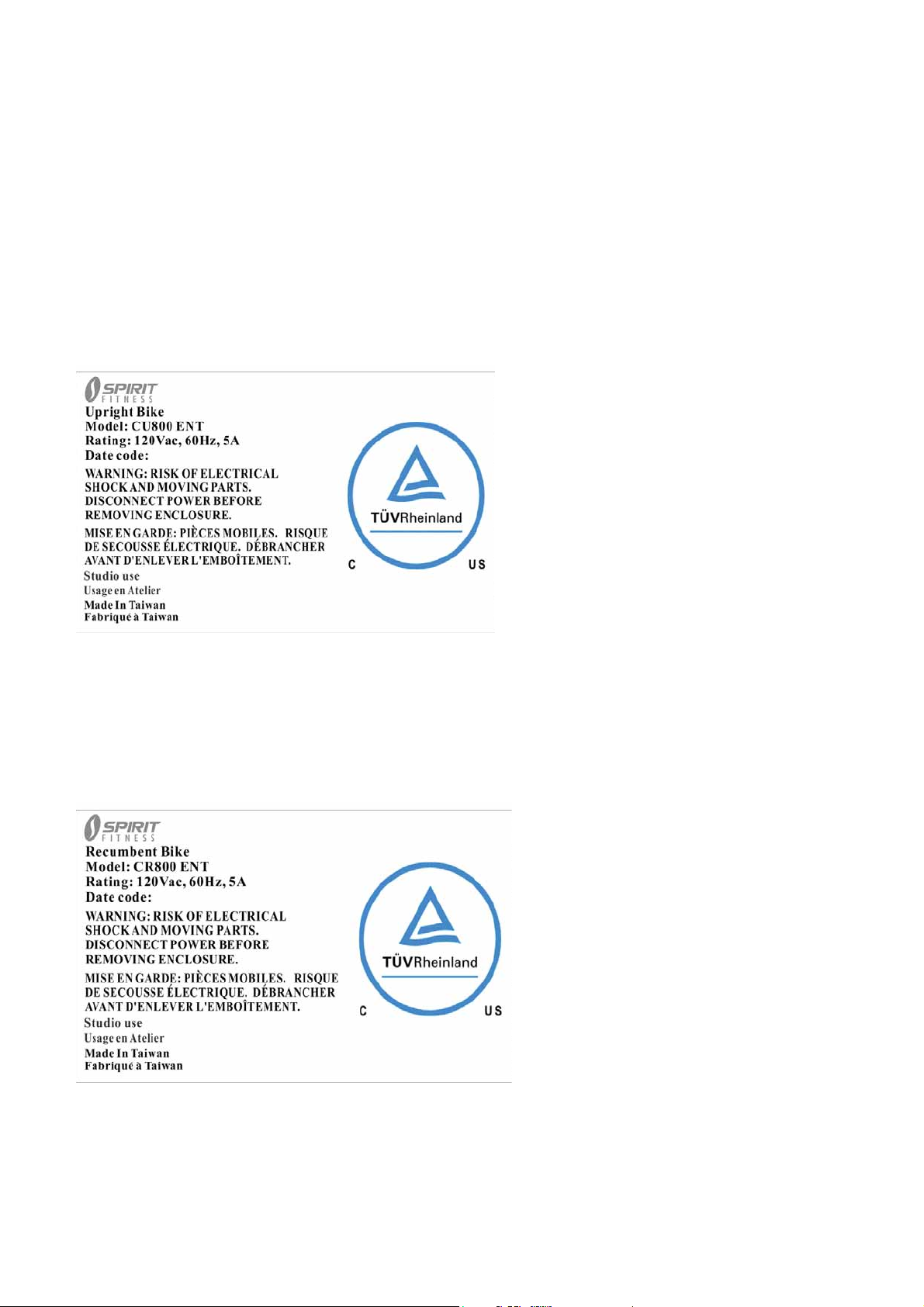
NOTE:
Article number: CU800 ENT
Use: Studio use
Max. user’s weight.:150 kg
NOTE:
Article number: CR800 ENT
Use: Studio use
Max. user’s weight.:150 kg
2

WARNING
: The equipment shell be installed on a stable
base and properly leveled.
Dyaco International Inc.
Head Office:12F, No.111,Songjiang Road, Taipei 104,Taiwan
Tel:+886-2-2515-2288 Fax:+886-2-2515-9963
Factory: No 1, Gong 1
Hemei Town, Changhua County 508, Taiwan
Tel:+886-4-7977-888 Fax:+886-4-7977-999
ST
Road, Cyuan Sing Industrial Park
3

Important Safety Instructions
WARNING
DANGER -
prior to cleaning and/or service work.
WARNING
bike on a flat level surface with access to a 120-volt,15-amp grounded outlet with only the bike
plugged into the circuit.
DO NOT USE AN EXTENSION CORD UNLESS IT IS A 14AWG OR BETTER. WITH ONLY ONE OUTLET
ON THE END.
Do not operate bike on deeply padded, plush or shag carpet. Damage to both carpet and
bike may result.
Keep children away from the bike. There are obvious pinch points and other caution areas
that can cause harm.
Keep hands away from all moving parts.
Never operate the bike if it has a damaged cord or plug. If the bike is not working properly,
call your dealer.
Keep the cord away from heated surfaces.
Do not operate where aerosol spray products are being used or where oxygen is being
administered. Sparks from the motor may ignite a highly gaseous environment.
Never drop or insert any object into any openings.
Do not use outdoors.
To disconnect, turn all controls to the off position and then remove the plug from the outlet.
Do not attempt to use your bike for any purpose other than for the purpose it is intended.
The hand pulse sensors are not medical devices. Various factors, including the user’s
movement, may affect the accuracy of heart rate readings. The pulse sensors are intended
only as exercise aids in determining heart rate trends in general.
Wear proper shoes. High heels, dress shoes, sandals or bare feet are not suitable for use
on your bike. Quality athletic shoes are recommended to avoid leg fatigue.
- Read all instructions before using this appliance.
To reduce the risk of electric shock disconnect your bike from the electrical outlet
- To reduce the risk of burns, fire, electric shock, or injury to persons, install the
CAUTION:
To assure continued FCC compliance:
1. Any changes or modifications not expressly approved by the grantee of this device
could void the user's authority to operate the equipment.
2. This equipment complies with FCC radiation exposure limits set forth for an
uncontrolled environment. This equipment should be installed and operated with
minimum distance of 20 cm between the radiator and your body.
3. Keep children under the age of 13 away from this machine.
SAVE THESE INSTRUCTIONS - THINK SAFETY!
4

MODEL: WB001
This device complies with Industry Canada license-exempt RSS standard(s). Operation is
subject to the following two conditions:
(1) this device may not cause interference, and (2) this device must accept any interference,
including interference that may cause undesired operation of the device.
This equipment complies with IC radiation exposure limits set forth for an uncontrolled
environment. This equipment should be installed and operated with minimum distance
20cm between the radiator and your body.
Cet appareil radio est conforme au CNR d’Industrie Canada. L’utilisation de ce dispositif
est autorisée seulement aux deux conditions suivantes :
(1) il ne doit pas produire de brouillage, et (2) l’utilisateur du dispositif doit être prêt à
accepter tout brouillage radioélectrique reçu, même si ce brouillage est susceptible de
compromettre le fonctionnement du dispositif.
Cet équipement est conforme aux limites d’exposition aux rayonnements IC établies pour
un environnement non contrôlé.
Cet équipement doit être installé et utilisé avec un minimum de 20 cm de distance entre la
source de rayonnement et votre corps.
5

IMPORTANT ELECTRICAL INSTRUCTIONS
WARNING
NEVER remove any cover without first disconnecting AC power.
If voltage varies by ten percent (10%) or more, the performance of your bike
may be affected. Such conditions are not covered under your warranty. If you suspect
the voltage is low, contact your local power company or a licensed electrician for proper
testing.
NEVER expose this bike to rain or moisture. This product is NOT designed for use out-doors,
near a pool or spa, or in any other high humidity environment. The operating temperature
specification is 40 to 120 degrees Fahrenheit, and humidity is 95% non-condensing (no water
drops forming on surfaces).
!
Important Operation Instructions
NEVER operate this Bike without reading and completely understanding the results of anyġ
Ɣ
operational change you request from the computer.
• Understand that changes in resistance do not occur immediately. Set your desired resistance
level on the computerġconsole and release the adjustment key. The computer will obey the
command gradually.
• NEVER use your bike during an electrical storm. Surges may occur in your household power
supply that could damage bike components. Unplug the bike during an electrical storm as a
precaution.
• Use caution while participating in other activities while pedaling on your bike; such as watchingġ
television, reading, etc. These distractions may cause you to lose balance which may result in
serious injury.
• Do not use excessive pressure on console control keys. They are precision set to function
properly with littleġfinger pressure.
• Always hold on to a handle bar while making control changes.
•
Do not use excessive pressure on console control keys. They are precision set to function
properly with little finger pressure. If you feel the buttons are not functioning properly with normal
pressure contact your dealer.
6

Grounding Instructions
This product must be grounded. If the bike’s electrical system should malfunction or breakdown
grounding provides a path of least resistance for electric current, reducing the risk of electric shock.
This product is equipped with a cord having an equipment-grounding plug. The plug must be
plugged into an appropriate outlet that is properly installed and grounded in accordance with all
local codes and ordinances.
DANGER
a risk of electric shock. Check with a qualified electrician or serviceman if you are in doubt
as to whether the product is properly grounded. Do not modify the plug provided with the
product if it will not fit the outlet; have a proper outlet installed by a qualified electrician.
This product is for use on a nominal 120-volt circuit, and has a grounding plug that looks like the
plug illustrated below. A temporary adapter that looks like the adapter illustrated below may be
used to connect this plug to a 2-pole receptacle as shown below if a properly grounded outlet is
not available. The temporary adapter should be used only until a properly grounded outlet, (shown
below) can be installed by a qualified electrician. The green colored rigid ear-lug, or the like,
extending from the adapter, must be connected to a permanent ground such as a properly
grounded outlet box cover. Whenever the adapter is used, it must be held in place by a metal
screw.
- Improper connection of the equipment-grounding conductor can result in
7
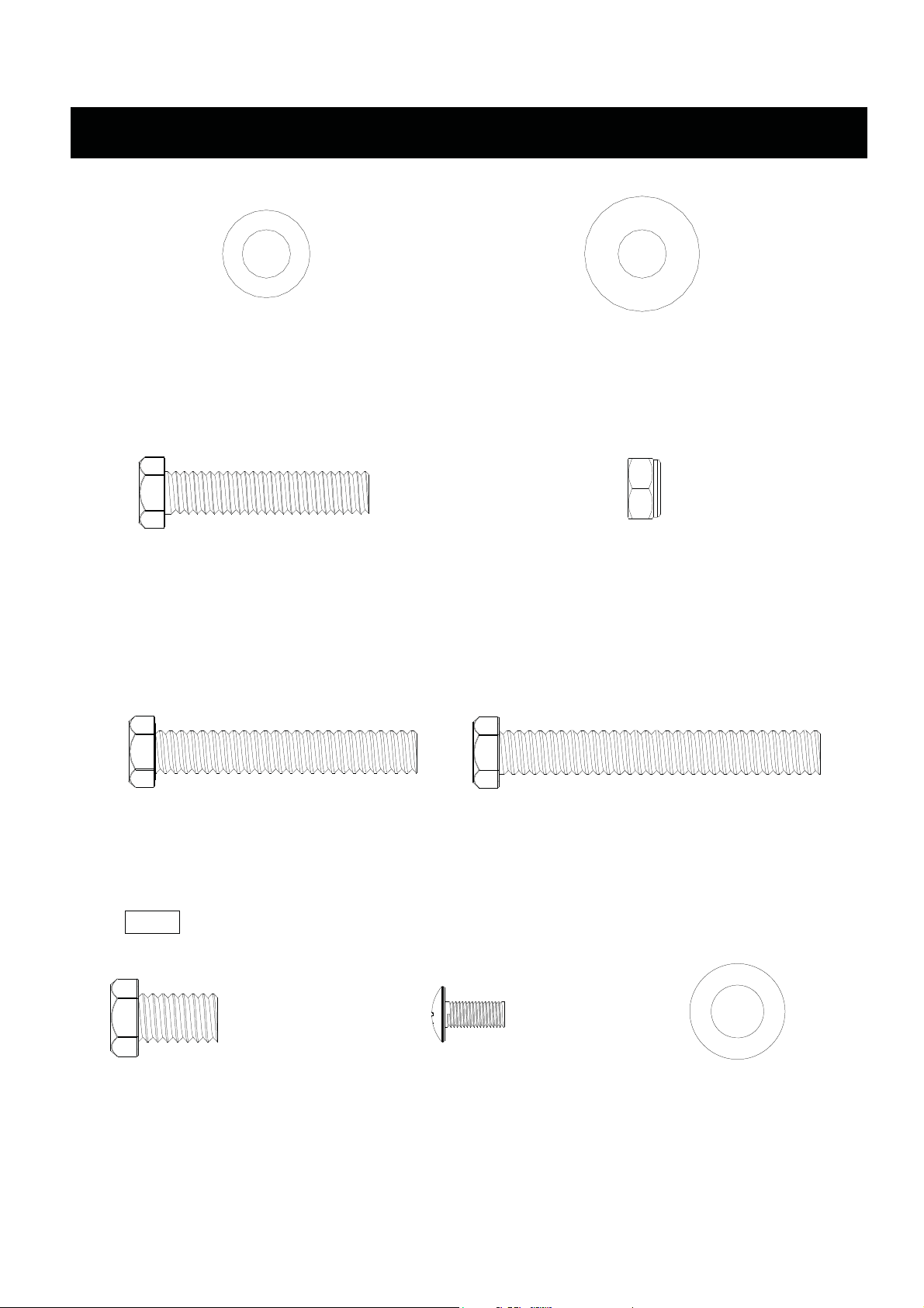
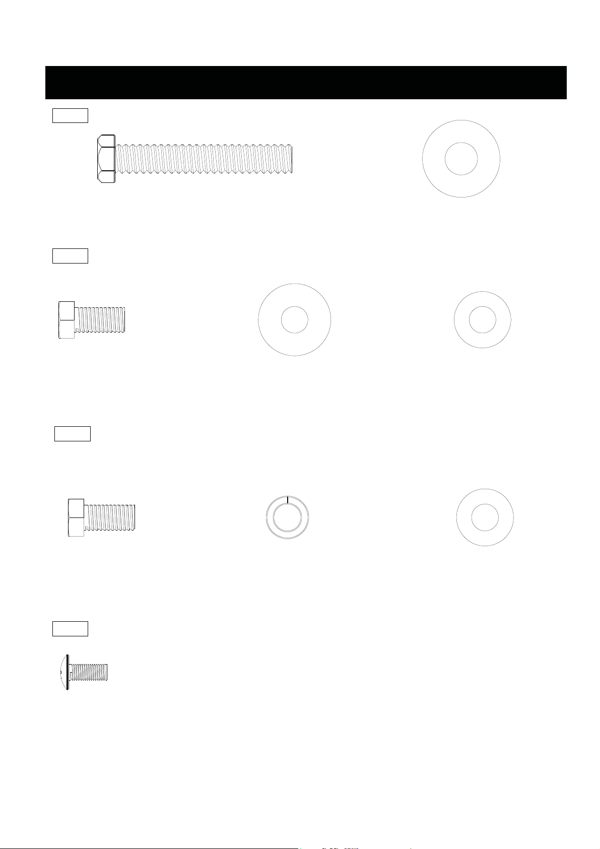
Assembly Pack Check List For RECUMBENT
#77 - 3/8"x19
Flat Washer (6pcs)
#71 - 3/8” x 2”
Hex Head Bolt (4pcs)
#84 - 3/8" x 25
Flat Washer (4pcs)
#89 - 3/8"
Nylon Nut (6pcs)
#65 - 3/8” x 2-1/4”
Hex Head Bolt (4pcs)
Step 2
#176 - 3/8” x 3/4”
Hex Head Bolt (6pcs)
#175 - 3/8” x 2-3/4”
Hex Head Bolt (2pcs)
#136 - M5 x 15mm
Phillips Head Screw (4pcs)
8
#77 - 3/8"x19
Flat Washer (6pcs)
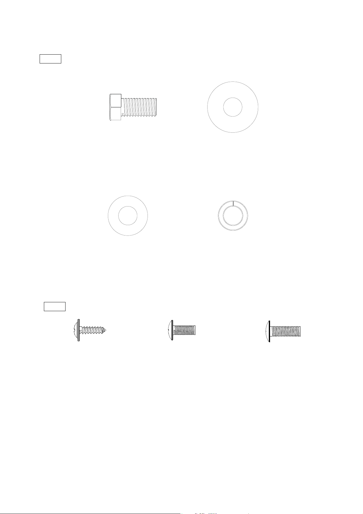
Step 3
Step 4
#68 - 5/16” x 5/8”
Hex Head Bolt (8pcs)
#76 - 5/16" x 18
Flat Washer (6pcs)
#83 - 5/16" x 19
Curved Washer (2pcs)
#82 - 5/16”
Split Washer (2pcs)
#105 - 4 x 16mm
Self Tapping Screw (4pcs)
#99 - M5 x 12mm
Phillips Head Screw (10pcs)
9
#186 - M6 x 18mm
Phillips Head Screw (4pcs)
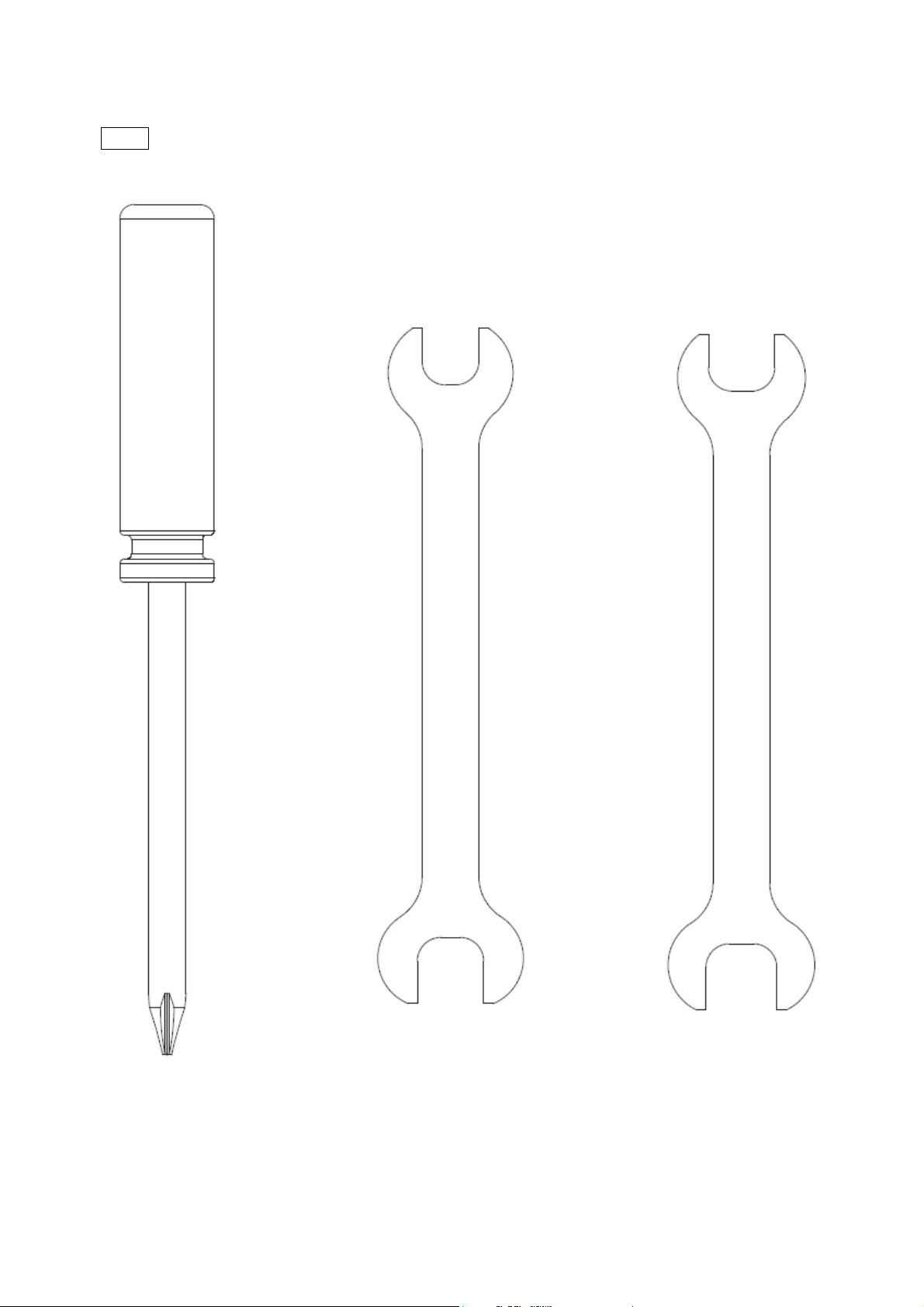
Tools
#114 - Phillips Screw Driver (1 pc)
#112 - 12/14mm Wrench (1 pc) #132 - 14/15mm Wrench (1 pc)
10
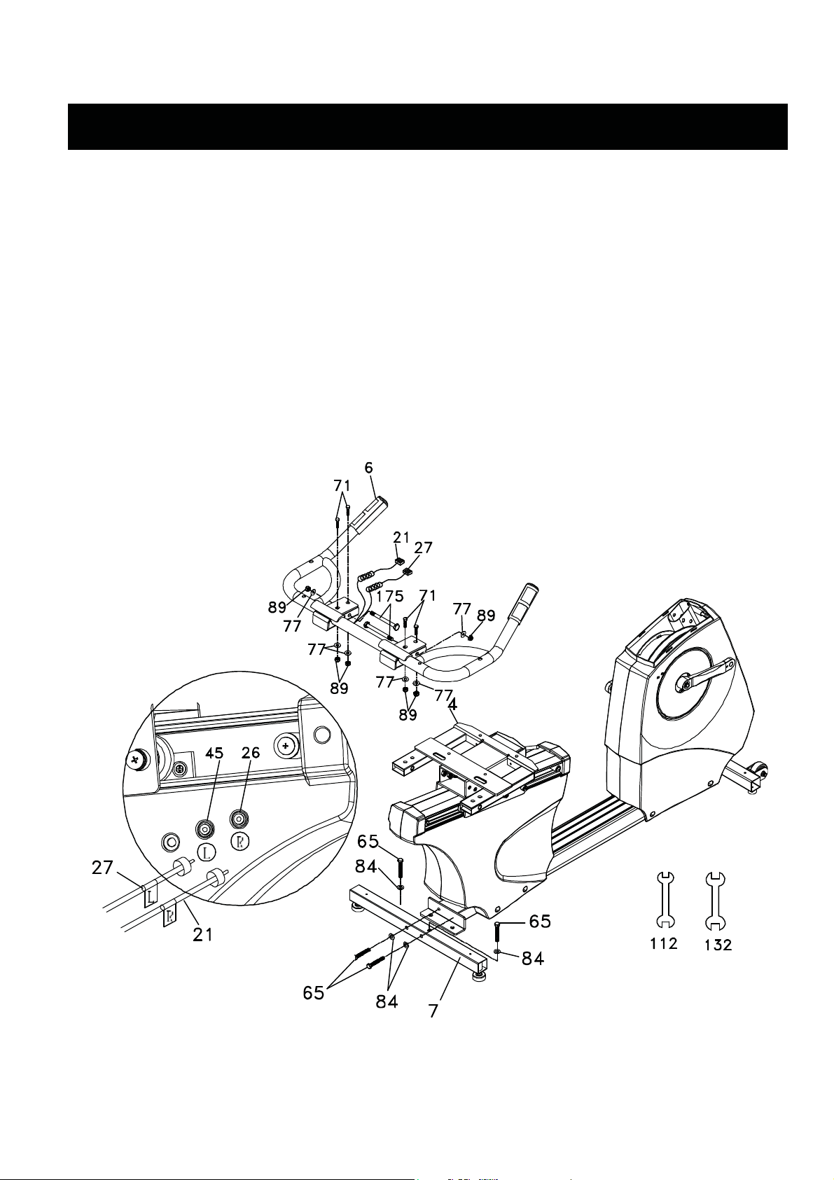
Assembly Instructions For RECUMBENT
STEP 1: REAR STABILIZER & SEAT HANDLEBAR ASSEMBLY
1. Install the Rear Stabilizer (7) onto the Main Frame (1) with the four 3/8”×2-1/4” Hex Head Bolts
(65) and four 3/8”×25×2T Flat Washers (84) by using the 12/14mm Wrench (112).
2. Secure the Seat Handle Bar (6) onto the seat carriage (4) with two 3/8"×2" Hex Head Bolts (71)
through the top holes in the Seat Handle Bar and fix with two 3/8"× 7T Nyloc Nuts (89) and 3/8"
× 19 × 1.5T Flat washers (77) side by using 12.14m/m Wrench (112) and 14.15m/m Wrench
(132). Repeat for another side.
3. Install two 3/8” x 2-3/4” Hex Head Bolts (175) through the side holes in the handlebars and fix
with two 3/8"× 7T Nyloc Nuts (89) and 3/8" × 19 × 1.5T Flat washers (77) by using 12/14m/m
Wrench (112) and 14.15m/m Wrench (132).
4. Connect the Handpulse W/Cable Assemblies (21, 27) to the mating connectors mounted in the
Rear Shroud (L) (35).
11
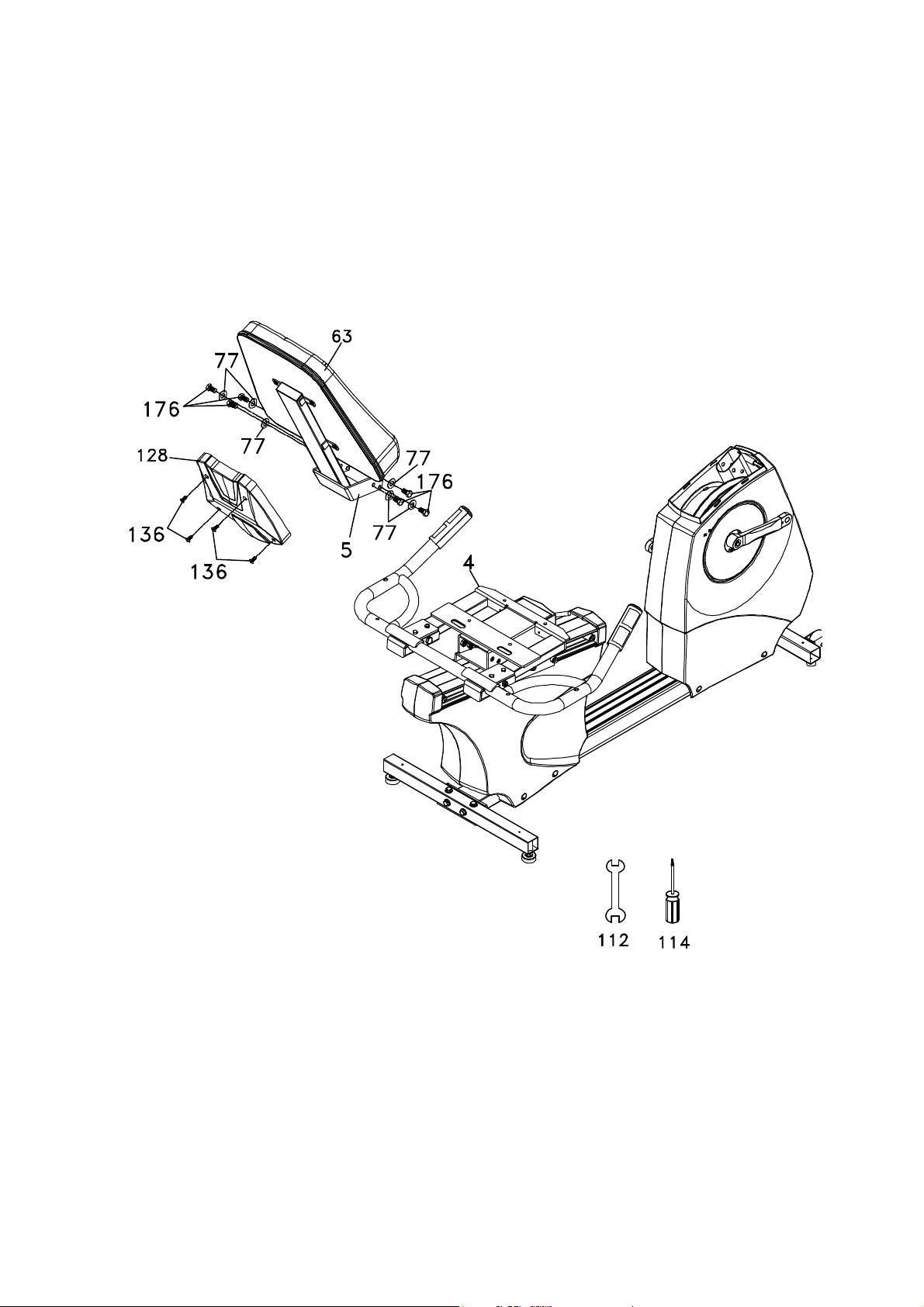
STEP 2: SEAT BACK
1. Install the Seat Back Cover (128) onto the Seat Back Frame(5) with four M5 × 15m/m Phillips
Head Screws (136) by using Phillips Head Screw Driver (114).
2. Install Seat Back Frame (5) onto the Seat Carriage (4) with six 3/8” x 3/4” Hex Head bolts (176)
and 3/8" × 19 × 1.5T Flat washers (77).
12
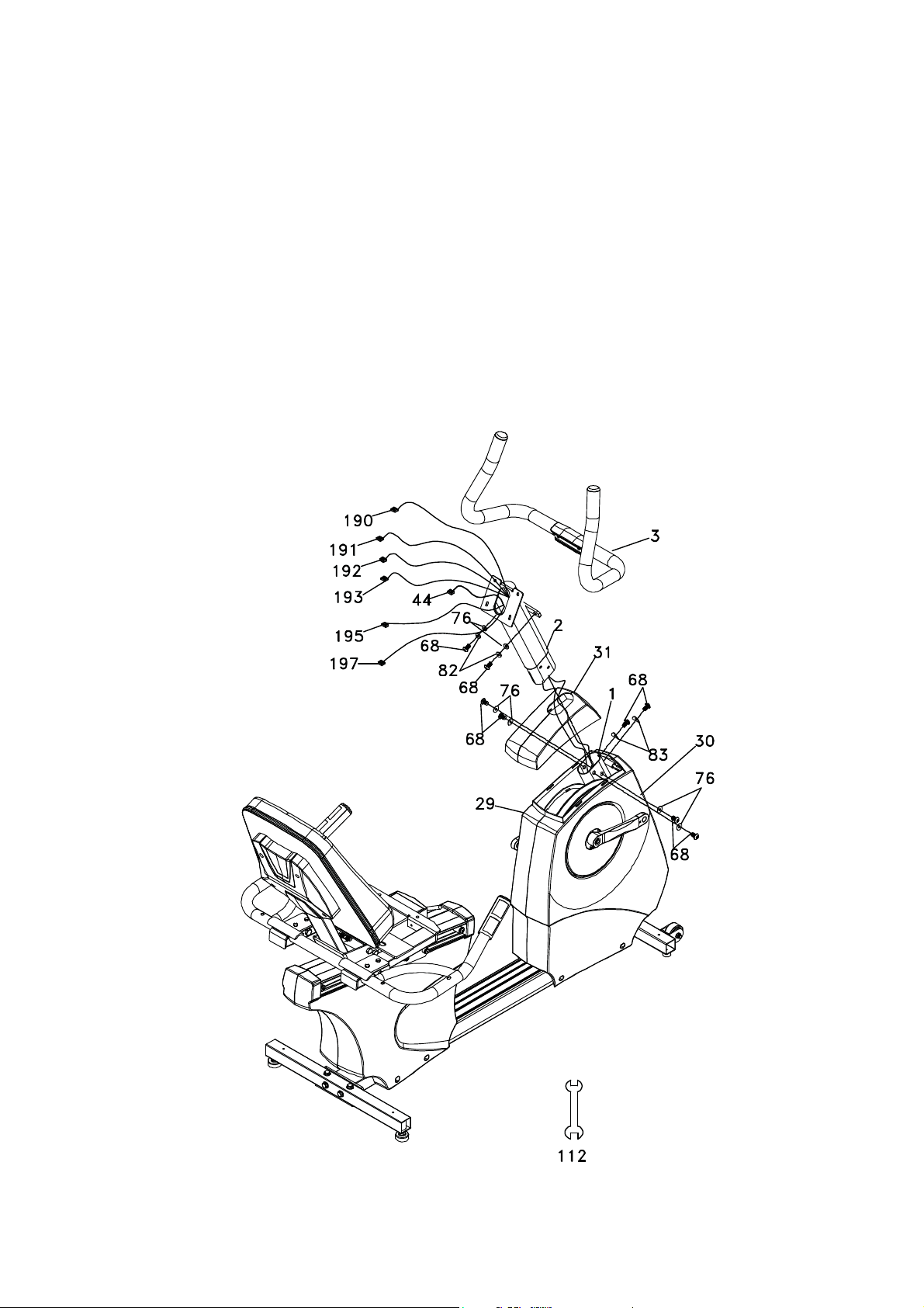
STEP 3: CONSOLE MAST ASSEMBLY
1. Install the console mast cover (31) onto the console mast (2), making sure it is facing the correct
direction as in the picture below. Run the Computer Cable (44), Handpulse Wire(195), CSAFE
W/Cable(190), TV Signal Cable(191), network W/Cable(192), Console Power Cord(193) and HDMI
Cable(197) through the bottom of the console mast tube and out the top opening.
2. Slide the console mast (2) into the Main Frame (1) being careful to not pinch the wires. Fasten the
console mast with six 5/16” x 5/8” Hex Head Bolts (68) and four 5/16" × 18 × 1.5T flat washers (76)
on the side bolts and two 5/16" × 19 × 1.5T curved washers (83) on the front bolts by using
12.14m/m Wrench (112).
Snap the console mast cover in place.
3. Install the Mast Handle bar Assembly (3) onto the console mast (2) with two 5/16” x 5/8” Hex Head
Bolts (68), 5/16" × 1.5T split washers (82) and 5/16" × 18 × 1.5T flat washers (76) by using
12.14m/m Wrench(112).
13
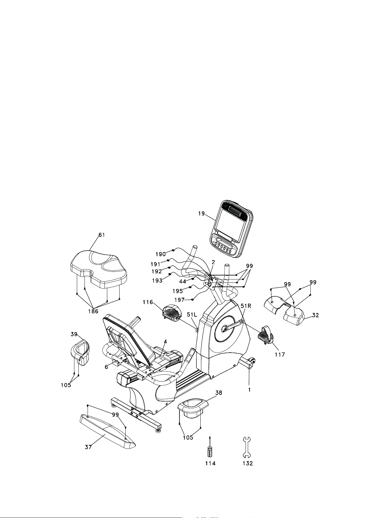
STEP 4: CONSOLE, SEAT, COVERS, PEDALS
1. Install the Seat (61) to the seat carriage (4) with four M6 x 18mm Phillips Head Screws (186).
2. Install the front and rear stabilizer covers (32 & 37) and secure to the Main Frame(1) with six M5 x
12mm Phillips Head Screws (99).
3. Connect the Computer Cable (44) with the Computer Cable (44), Handpulse Wire(195), CSAFE
W/Cable(190), TV Signal Cable(191), network W/Cable(192), Console Power Cord(193) and HDMI
Cable(197) to the corresponding connectors on the back of the console(19). Install the console onto
the console mast and secure with four M5 x12mm Phillips Head Screws (99) by using Phillips Head
Screw Driver (114).
Being careful to not pinch the wires.
4. Install the left and right Drink Bottle Holders (39 & 38) to the Seat Handle Bar(6) with four 4 × 16
m/m Sheet Metal Screws (105) by using Phillips Head Screw Driver (114).
5. Install the Pedals (116 L, 117 R) into the Crank Arms (51L, 51R) by using 14.15m/m Wrench
(132).Remember that the left pedal has a reverse thread and will be screwed into the crank in the
opposite rotation from normal threads. There is an “L” stamped into the end of the threaded post of
the left pedal and an “R” in the right. Make sure to tighten the pedals as much as you possibly can.
It may be necessary to re-tighten the pedals if you feel a thumping during pedaling the bike. A
clicking noise, or thumping, sound during pedaling is usually caused by the pedals being too loose.
14
Assembly Pack Check List For UPRIGHT
Step 1
Step 2
#50 - 3/8” x 2-1/4”
Hex Head Bolt (4pcs)
#71 - 3/8" x 25
Flat Washer (4pcs)
#51 - 5/16” x 5/8”
Hex Head Bolt (7pcs)
Step 3
#51 - 5/16” x 5/8”
Hex Head Bolt (2pcs)
Step 4
#99 - 5/16"x19
Curved Washer (1pcs)
#103 - 5/16”
Split Washer (2pcs)
#72 - 5/16"x18
Flat Washer (6pcs)
#72 - 5/16"x18
Flat Washer (2pcs)
#58 - M5 x 12mm
Phillips Head Screw (12pcs)
15
 Loading...